I SHIFT TO FSK ON 30 METER QRSS

The online grabber of Johan, ON5EX, provided instant gratification this morning. Right after I finished some modifications that I hoped would result in a Frequency Shift Keying signal on the 30 meter visual QRSS band, looked at the grabbers and found this. That’s me. It is a kind of “upside down” FSK. Look along the bottom of the square wave and you can read the CW.

I used a fairly standard approach to get the FSK, but with a twist: I added the usual LED and a cap to the oscillator circuit. Now, on key down, the positive voltage from the keyer causes the LED to conduct, putting the additional cap into the circuit. But here is the twist: for the capacitor, I just used some of that twisted-up two conductor insulated wire that often comes with cheap old (mono) ear phones. In the old days this would have been called a “gimmick” capacitor. I started out with 3 or four inches. Using Spectran to monitor the amount of shift, I just cut off bits of the wire until the shift was at the desired 5 Hertz. I just clipped away at the wire until the shift looked about right.

The rig is now key down all the time, and even though power out is still only about 20 miliwatts, I have the final in Class A, so I actually had to put a heat sink on it. But there is still no need for a muffin fan, or liquid cooling or anything like that!

Five hertz isn’t much of a shift. I think I can hear it, but barely. Shows up nicely on the grabber screens.

It was a lot of fun to start out with a vision of what I wanted the signal to look like, then actually make it happen.

Beacon Final Amp Goes Bad

All of a sudden the power output meter on my 30 meter beacon (MEPT) transmitter stopped jumping up and down. The oscillator was still running, and the keyer was working, but output had obviously dropped considerably. I started troubleshooting and my attention started focusing on the 2N2222A in the final. The stage runs Class A, with long QRSS key down periods. The emitter resistors get a bit warm. I replaced the transistor with a new 2N3904 and — BINGO — output was back up in the tens of milliwatts.

I did some tests on the 2n2222A. With a VOM I looked at forward and reverse bias resistance across both junctions, comparing the part from the rig with a new part from the same batch. In the transistor that went bad there is a lot more reverse bias current across the base-collector junction.

So, what happened? Any ideas?

This was one of those very satisfying repairs in which you quickly zero in on the problem, change one part, and then put the gear back into action. The victory was made even sweeter, when, a few minutes after I put the rig back on the air, I noticed my QRSS CW signal on I2NDT’s online grabber.

I’m almost finished with my 10.140070 frequency standard. Armed with that, I’ll be free to experiment with FSK keying (without fear of being unable to find my way back to the 100 Hz -wide QRSS frequency band). 73 from Rome

Bicycling across 30 meters

I was having lunch today, thinking about ON5EX’s QRSS bicycle. I’ve showed it to my wife and kids — we all think it is really very clever. But then I realized that at the same time I’ve been admiring Johan’s bicycle artistry, I’ve been using his online grabber: http://www.on5ex.be/grabber/grabber.html

I wondered how he transmits and receives at the same time. Then I noted the black stripes on the grabber screen, each about one bicycle long. Clever fellow!

Inspired by Johan, I have put my humble QRSS3 CW MEPT back in the band. I’m at around 10140070, visible on Claudio’s grabber now. Reports would be appreciated.

VK6DI Comments on QRSS Bandwidth, Modulation

David, VK6DI, is one of the Knights of QRSS. He sent in this very nice note about bandwidth and modulation methods in QRSS. Thanks David!
————————-
Yes, QRSS3 bandwidth is indeed 0.34 Hz. ON7YD has an excellent ‘CW bandwidth’ reference at

http://www.qsl.net/on7yd/136narro.htm#Bandwidth

Clearly ‘hard keying’ rather than ‘soft keying’ of a CW (or FSK) transmitter will increase the transmitted bandwidth. In a practical sense QRSS transmissions key the carrier at such infrequent intervals that an occasional key click every 3 seconds (for dots) or 9 seconds (for dashes) should be of little consequence QRM wise, and especially so when using QRPp. Ideally however it is preferable to control the carrier’s rise and fall times during keying. Sometimes just simple R-C filtering is used for carrier wave-shaping, however ‘Raised Cosine’ rise and fall times such as used for PSK31 are optimal, albeit much more difficult to produce. ‘Raised Cosine’ shaping also seems to make good ‘intuitive sense’. Hence some compromises as to carrier wave shaping are usually the order of the day.

A convenient way to become familiar with QRSS’s bandwidth requirements is to run the program “Spectran” (by I2PHD & IK2CZL), and to then observe the preset QRSS parameters. Spectran is available for download at –

http://www.weaksignals.com

As with the program Argo, Spectran also has a series of predetermined settings for all standard QRSS speeds. Those settings have been optimized for best results when receiving QRSS. This is an extremely important factor for most beginners. Whilst it is true that the more sophisticated FFT programs offer tremendous flexibility of user settings, they also carry a proportionally higher risk of operator confusion.

To obtain further insights into QRSS bandwidth requirements try running Spectran and then select a ‘Mode’ via drop-down menu –

Now observe the “Show Controls” menu –

Note that 11050 / 32768 = 0.34 Hz FFT bin bandwidth. Each bin will take 32768 / 11050 or about 3 seconds to fill, and 3 seconds is the duration of a QRSS3 dot.

Similar calculations can be obtained for other QRSS speeds – QRSS10, QRSS30, etc. Note that both bin size and waterfall scrolling speed are factors that will determine the final visual S/N ratio. For that reason it is best to stick with easy to use programs such as Argo when beginning QRSS activities. Many seasoned QRSS operators use Argo with excellent results, as you can observe on many of the on-line grabbers.

QRSS10 is not considered usable on HF. It is impossible to keep even the most stable transmissions to within a few QRSS10 FFT bins at the receive end of the path due to continually varying ionospheric conditions that will disperse the signal. The final ‘visual S/N ratio’ is dependent upon capturing as much energy in as few FFT bins as is possible.

QRSS3 on HF over long paths often results in an ambiguous visual display following QSB. For example – a dash may appear as a series of dots. Is the character below an “O” or a “Z”?

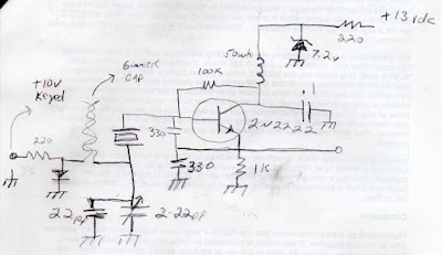
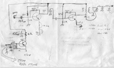
Switching to QRSS6 and FSK-CW seems to partially resolve this problem, but not completely. Slower ID’s will obviously allow more time to “visually integrate” the signal. That is, to make a ‘decision’, as to whether the portion just observed on-screen was a dot or a dash. The trade off (as always), is the rate of information transfer. QRSS6 transmissions are best received as QRSS3 in this instance, and look fine on the QRSS3 grabbers. FSK-CW transmission has additional advantages, apart from any perceived improvement in signal readability. FSK-CW is very easy to generate from an existing QRSS keyer, and cheap Red LED’s when reverse biased seem to function adequately as Varactor diodes for FSK modulation purposes. A shift of about 5 Hz is all that is required. The best advantage with FSK-CW however, comes from not having to key the transmitter’s carrier on and off. That helps with transmitter frequency stability when interstage isolation from the Crystal oscillator may be poor, as is often the case with simple transmitter designs.

There is certainly room for more experimentation with Visual Modes. The sheer variety of approaches to the modulation problem can be quite interesting to watch at times, but in the end the same old constraints remain. Dual freq CW (DFCW) is yet another option, and has the advantage over QRSS Morse that both dots and dashes can be the same length. So ID’s are faster than for normal QRSS.

Ref – http://www.w1tag.com/Modes.htm#DFCW_ENTRY

One final factor not always appreciated by newcomers to the ‘slow modes’ is that the ‘visual gain’ advantage of QRSS over that of traditional speed Morse does not arise from the use of narrow receiver IF filters as might be expected. The advantage results from the narrow FFT bin size (Resolution) within Argo / Spectran – namely 0.34 Hz at QRSS3 speed. Narrow filters may be useful to exclude strong QRM that otherwise might impact the receiver’s AGC, but they make no difference to the visual S/N ratio. (All else being equal.)

Unfortunately I think that it is fairly unlikely that I will see very many EU signals until conditions improve. So far this year I have caught only one EU signal. Conditions have been really poor these past 12 months or so. When the sunspots return I’m sure everybody will see many new EU and US stations. DL6JAN has previously made it down into VK with 5 mW, along with many other stations that were running 50 mW to 200 mW or so, and all with minimal antennas.

Ref – http://www.proehl-elektronik.de/qrss/dxrprt_e.html

Good luck with your QRSS experiments, I hope you will continue to have fun with the mode.

Regards,

David, VK6DI.


VK6DI Web page: http://tinyurl.com/lp2vv

VK6DI Captures: http://tinyurl.com/2lxyy5
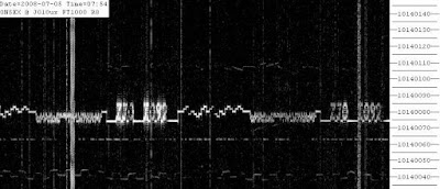
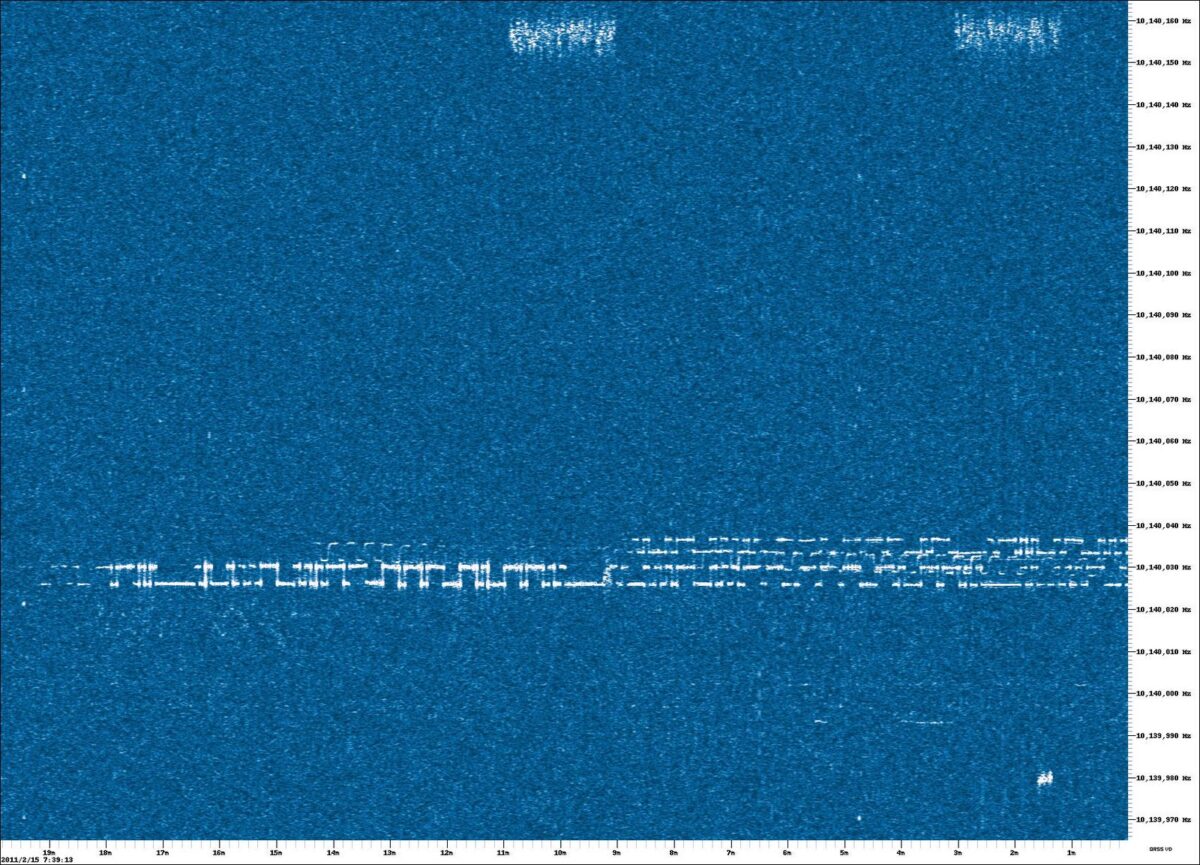
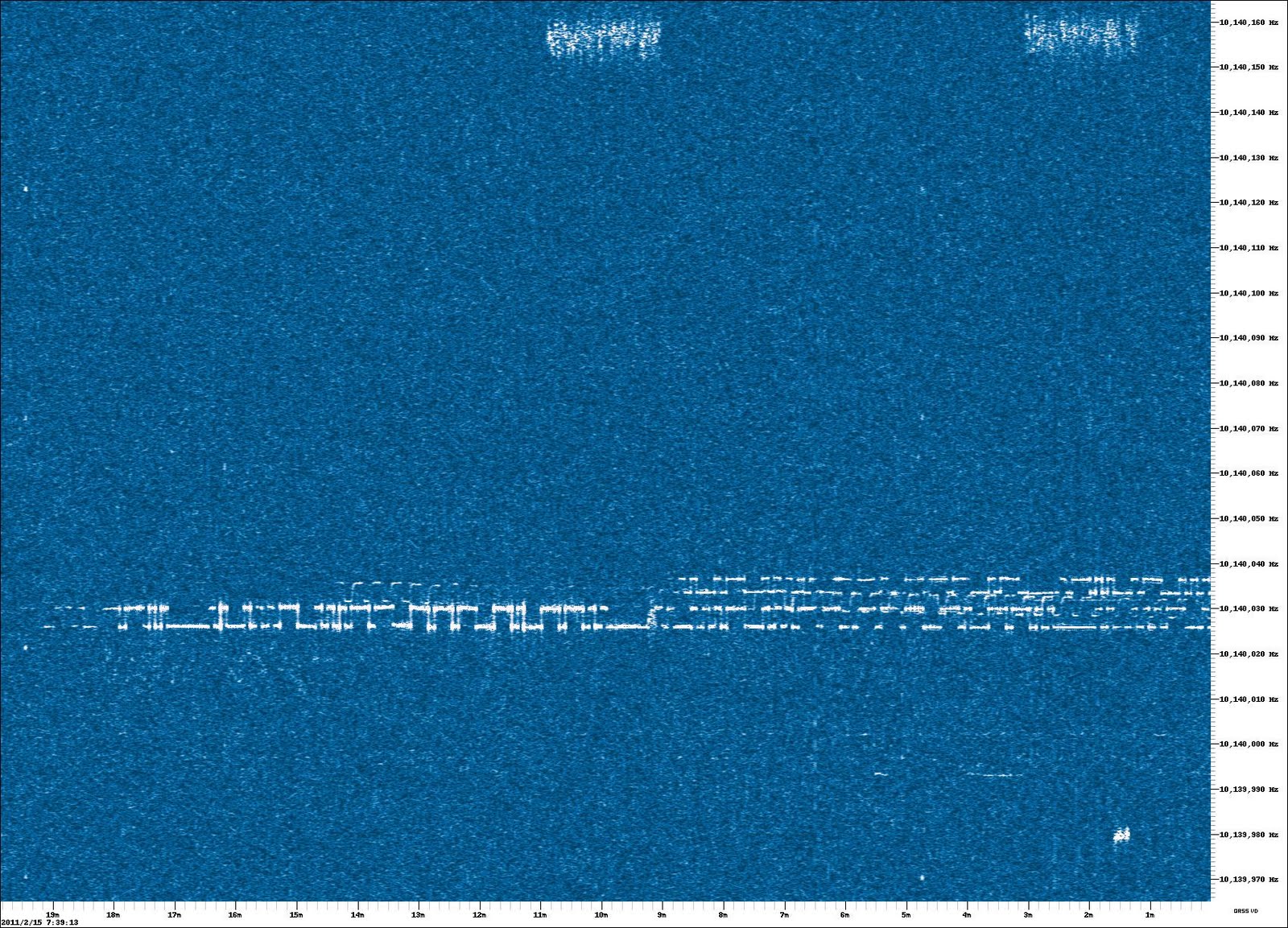
Loops and QRSS

On QRP-L there has recently been some discussion of the effectiveness of small loop antennas. Some hams in Northern Italy are doing something very interesting in this area. They have two identical QRP (1 watt) QRSS transmitters on 30 meters. They are keyed simultaneously, but one antenna is connected to a standard vertical antenna (with a very good radial system), while the other goes to a small, resonant CFA loop. By looking at the various QRSS on-line grabbers out there, you can get a real sense of how the two antennas perform. I just took at look at VK6DI’s grabber — I could clearly see the signal from the vertical, and could see quite a bit of the signal from the loop (see above at around 10140040 — the loop signal is a few Hz above).

Claudio, I2NDT, has a good web page describing the experiment:

http://digilander.libero.it/i2ndt/pagine/Dual%20Beacon.htm

The QRSS Knight with the Nobel Prize


We are in some very distinguished company on the QRSS “Knights” mailing list. Joe Taylor, K1JT, is active in the group. Joe won the Nobel Prize in Physics in 1993. His biography includes references to ham radio that will warm the hearts of all Knack sufferers: K1JT’s bio

This year, Joe created a new piece of software that is being used by many of the Knights. It has a name that will appeal to QRP’ers. Here is a description:

WSPR is the name of a computer program.
It is pronounced "whisper",and stands
for "Weak Signal Propagation Reporter";
it implements transmitting and receiving
functions for a digital soundcard mode
called "MEPT_JT", which stands for
"Manned Experimental Propagation
Tests, by K1JT".

WSPR generates and receives signals
using structured messages, strong
forward error correction,
and narrow-band 4-FSK modulation. Its
principal design goal is reliable
copy at very low signal levels. In
practice it works well at
signal-to-noise ratios down to -27 dB in a
reference bandwidth of 2500 Hz.

Joe recently released a new version of WSPR, so if you are going to give this a try, make sure you do so with the most recent release. You can download WSPR 1.0 (r972) from

http://physics.princeton.edu/pulsar/K1JT/WSPR100.EXE

My Beacon (MEPT) Circuit

Guys have been asking to see the schematic for my 30 meter QRSS MEPT beacon. Here’s the oscillator circuit. This actually started out on a plane ride. My son Billy and I were talking about electronics. I drew a basic schematic for an oscillator, and we built one when we got home. It originally used a 20 meter crystal. At one point we were playing “find the oscillator” — hiding it somewhere in the house, and tracking it down with a Sony shortwave receiver. Now, with some modifications, it is the first stage in my 30 meter MEPT beacon.

An ugly schematic for a rig built with the ugly construction technique. Nothing fancy here. Two feedback amps and a PNP transistor as a switch to key them. I let the oscillator run continuously. (Let me know if you can hear the “backwave”!) About 20 mw out. As you can see, it doesn’t take much to get a QRSS signal on the air.

The QRSS View from ON5EX — July 5, 2008


I wanted to give you guys a sense of what you can see on the QRSS Grabbers. The grabbers are just the output screens from the Argo or Spectran (or other) software that have been placed on-line, updating every few minutes. In the screen shot above, you can see the sophisticated signal of Eddie, G3JZO, pounding into Belgium (this is the Grabber of Johan, ON5EX). My much more basic effort is visible as a line of Morse Code just below Eddie’s sig. Above Eddie you can see the “snake CW” of IQ4FJ. Along the bottom right of the screen, you will see the square wave signal from the 5 mw solar powered beacon of Paolo, IZ1KXQ (scroll down a bit to see his rig, and his schematic). I think the vertical stipes must be lightning.

Check out I2NDT’s Grabber Compendium (but be aware that not all of them are on 24/7):
http://digilander.libero.it/i2ndt/grabber/grabber-compendium.htm

In this screen shot from I2NDT’s Grabber, you can see the effect of me turning the air conditioning on in my shack. I have added a bit of insulation (an ARRL Handbook placed on top of the beacon box!) and things seems to have stabilized. With the entire “QRSS band” only 100 hertz wide, it doesn’t take much to slide your signal all the way across the band!

Cleaning up my QRSS Signal

This week I worked to improve the quality of my 30 meter QRSS signal. At first I was pleased to just be in the band and visible on the grabbers. But soon I grew jealous of the very clear and clean dots and dashes of IK0IXI and others. My droopy dashes (“Italian tears”) were getting embarrassing. Making matters even worse, when conditions were good, very noticeable key clicks became visible on the grabber screens. These became known among the Knights of QRSS as “shop hooks.” I thought they made my signal look like some sort of Arabic lettering. Clearly something had to be done.

Yesterday I put a seven volt zener diode voltage regulator in the oscillator circuit. I also drastically reduced the size of the the capacitor that connects the oscillator to the first RF amplifier. This seems to have done the trick. The clicks are gone and the dashes no longer droop. Power out is now down from 200 milliwatts to 20 milliwatts. That’s fine — this puts me in the power range favored by the Knights.

The narrow-band nature of QRSS work makes imperfections very visible. A chirp or click that would be undetectable on ordinary CW becomes very apparent in QRSS. This morning when I adjusted the air flow from the shack air conditioner, I inadvertently sent the stream of cool air toward the beacon transmitter. With the On5EX beacon on my screen, I could almost immediately see the resulting frequency change!

The on-line grabbers are really fantastic. They give you and almost real-time ability to check band conditions. Almost all day I can see my 20 milliwatt signal arriving at ON5EX. Depending on time of day, you should be able to see my signals here: http://www.on5ex.be/grabber/grabber.html Look for me around 10140060 (+/- air conditioning).

Why isn’t there more QRSS activity in the USA? Why are there so few American grabbers?

Over the Alps with 5 Milliwatts and Solar Power


Yesterday morning the lower portion of the 30 meter QRSS band was dominated by three Italian stations: Near the bottom of ON5EX’s grabber screen was the very clear and FB CW of Fabio, IK0IXI. Fabio runs about 50 milliwatts to a Windom and operates from Civitavecchia, a beautiful coastal town about 20 miles from Rome. Here you can take a look at his rig, and his schematic: http://www.geocities.com/ik0ixib/bcn.html A bit further up were the droopy dashes of yours truly, 200 mw (QRO!) to my all-purpose end-fed wire. And a bit further up from me was the very interesting signal of Paolo, IZ1KXQ. Paolo runs 5 milliwatts from a super-simple solar powered rig (see above) that resides on the roof of his house. It puts out a distinctive square wave sig.

IKoIXI’s crystal is in an oven and is temperature stabilized. He stays on the same freq all day. We’ve found that my signal seems to drift down in freq during the course of the day, as Rome heats up. It moves about 15 hz down from early morning to afternoon. IZ1KXQ’s rig is more exposed to the heat, and seems to move quite a bit more, and his sig moves UP in freq. I think this drifting adds to the QRSS fun.
FB Paolo! FB Fabio!

Here is IZ1KXQ’s schematic:

Crossing the Pond on 200 milliwatts QRSS


As you can probably tell, I was really pleased to get my little QRSS station in operation. But then came some icing on the cake: Vernon, VE1VDM, sent a screen shot (above) that showed the unmistakable traces of my somewhat chirpy signal. Look around 10140020 Hz . See those kind of droopy dashes? They’re mine! (Johan, ON5EX, called them “Italian tears.”) Hooray! Crossing the pond on 200 milliwatts!

Of course, this is no big deal in the QRSS world. 200 milliwatts is decidedly QRO for these fellows. I feel some pressure to reduce power. I also feel the urge to clean up the chirp, but then again, the Italian tears make spotting the signal easier.

For a great explanation of how QRSS allows you to pull signals out of the noise see ON7YD’s excellent article: http://www.qsl.net/on7yd/136narro.htm

The online “grabbers” add a very interesting dimension to this. You can watch the band from stations around the world simultaneously. Take a look at I2NDT’s grabber compendium:
http://digilander.libero.it/i2ndt/grabber/grabber-compendium.htm

Here’s something else that I found really cool: I can watch the grabbers on my Blackberry! So, the other day, with my beacon on, as I made my way through central Rome on the 63 bus, I pulled out the Blackberry and opened ON5EX’s grabber page. There I could see my droopy dashes at 10140020. Now I’ve got my eye on the grabber of Laurence, 9V1LF, in Singapore; I hope to put some Italian tears on his screen soon.

Guys, this real “essence of QRP” stuff. I’m reading Ade Weiss’s book on the history of QRP, and I often find myself thinking that The Old Man and the QRPers of yesteryear would very much approve of QRSS.

It may seem complicated, but it is not. The transmit systems are just milliwatt crystal-controlled transmitters and some sort of keyer (mine is from K1EL). For receive, all you need is a cable from your receiver to your soundcard, and some free software.

We need more QRSS activity from the States. When will AA1TJ put one of those Zener Diode rigs on 10140030?

QRSS Success — Signals Visible in Online Grabbers


Shortly after recording SolderSmoke 86 (in which I shared my tale of QRSS woe), I solved my calibration problem. IK3NWX has a CW beacon on 10141800 Hz. I fired up the Spectran soundcard program, and put the output of my Drake 2-B into the line in connector. With the 2B’s bandpass wide, I tuned NWX’s beacon to the top of the display. I then adjusted the trimmer cap on my oscillator to put me 1750 Hz below NWX. Eccolo! That put me in the 100Hz wide QRSS band. Almost immediately I could “see myself” on some of the on-line “grabbers.” Vic, G3GKI, sent a screen shot (above) You can see some chirp on my signal. I might fix that, but I might leave it as is to make the signal more easily recognizable.

Eddie, G3ZJO, also sent a screen shot. I think this one is from an online grabber located in Northern Italy. You can see Eddie’s far more sophisticated signal higher up in the display. My more rudimentary effort appears below. You can make out my call.

The online grabbers are a real hoot. My favorite is that of Johan, ON5EX. Check it out and see if you can see my 200 milliwatts reaching out across Europe. look for me around 10140020. Johan’s page updates every minute or so:

http://www.on5ex.be/grabber/grabber.html

Jason, the Argonauts, and QRP

You don’t often find beauty in software read-me files, but I found some in those of I2PHD and IK2CZL. Take a look at this. It is from the read-me file for a Slow Speed CW program:
—————————-

ARGO -- A QRSS Viewer by I2PHD & IK2CZL

Argo is program for viewing QRSS signals, i.e. very
slow CW, or DFCW signals, i.e. slow CW where dots and
dashes are of the same length, but offset in frequency
by a few Hertz, or even a fraction of an Hertz.

The name Argo is taken from that mythical ship which,
with the Argonauts on board, headed to Colchis,
in the quest for the Golden Fleece, much like the LF
Hams are in search of that fraction of dB of S/N which
will allow them to make that elusive QSO.

--------------------------

Here is where you can get the Argo software.
Free! And lots of other good programs
(check out Spectran):

http://www.weaksignals.com/

Bravo Alberto! Grazie!

QRSs QRPp


I blame Hans Summers for this. His articles in SPRAT on very slow speed, very low power CW on 30 meters have caused me to develop a new set of Knack symptoms. I now listen intently to CW that is so slow that by the time I get to the end of a letter, I’ve forgotten if it started with a dit or a dah. I’ve become intimately familiar with the refresh rates of strange web sites known as “Grabbers” (I’d never heard of them before. See above for a sample.) And for the first time in my life as a radio amateur, using crystal control is no guarantee that I’m “in the band.”

My 30 meter QRSs 200 mw “MEPT” beacon is on the air, but no one has heard me yet. This is almost certainly due to the fact that I’m probably outside the QRSs “band.” This band is only 100 HERTZ wide! I’m using a 10.140 Mhz crystal, but the circuit values of my oscillator could easily put me out of that band. And Murphy struck: Just days before I started all this, my frequency counter died. My trusty Drake 2B is of little help in measuring frequency to this accuracy: The dial increments are 10 KILOhertz! And the 2B suffers from a problem totally unfamiliar to those who have grown up with glowing numerals: DIAL PARALAX! (It sounds like Knack-related disease, doesn’t it? “I’m sorry m’am, your son Dilbert also has a bad case of DIAL PARALAX!!!”)

Wish me luck. Don’t blame me if you succumb to QRSs madness. Remember: it is all Hans Summers’ fault.