 |
| Q-31. “Roll-bar” on cap. Note RGS316 coax between stages. Country markings on tuning dial |
SolderSmoke Podcast #221 is available:
25 April 2020
http://soldersmoke.com/soldersmoke221.mp3
Obviously no travelogue. QUARANTINE. SITS.
Good news: Lawyers at Dewey Cheatham and Howe report that SolderSmoke will NOT be taken off the net for brazen promotion of the S-38E receiver.
Also some good news on the FT8 vs. FT-FAKE issue. That report itself was fake.
PETE’S PROJECTS:
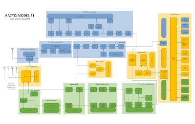
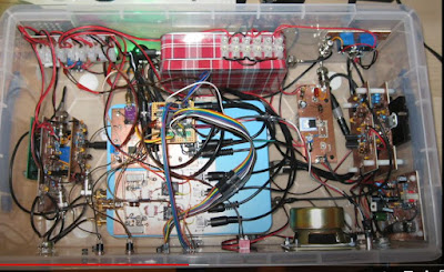
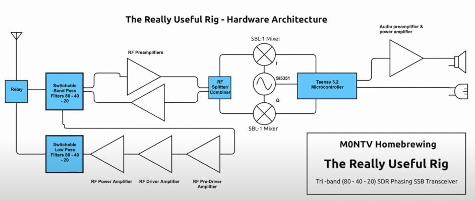
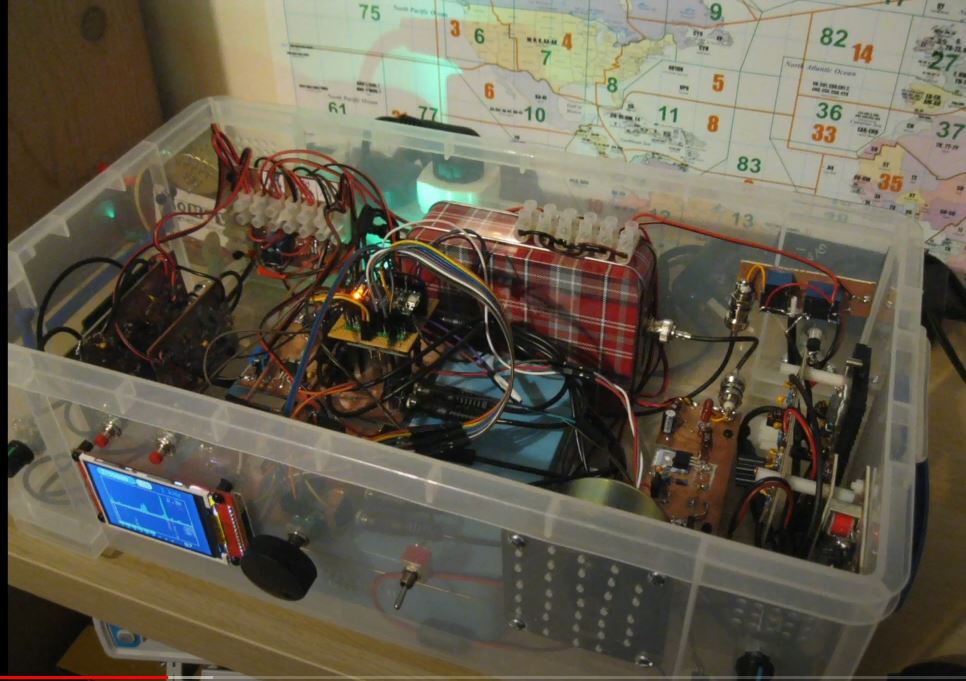
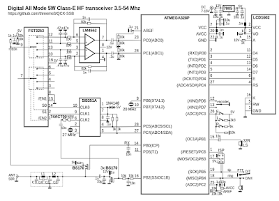
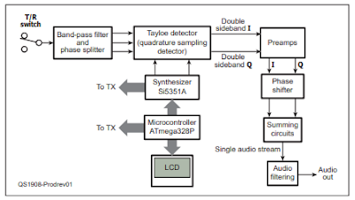
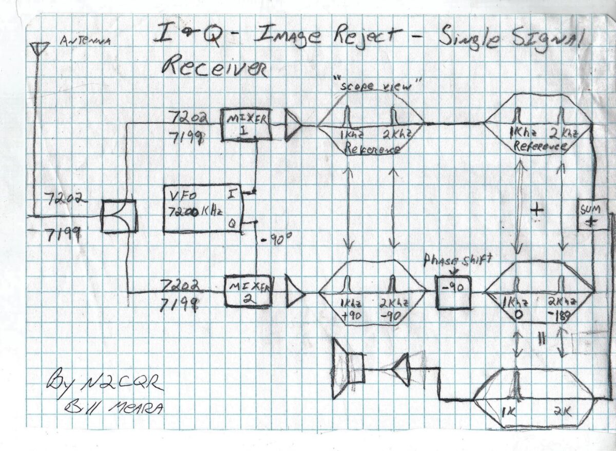
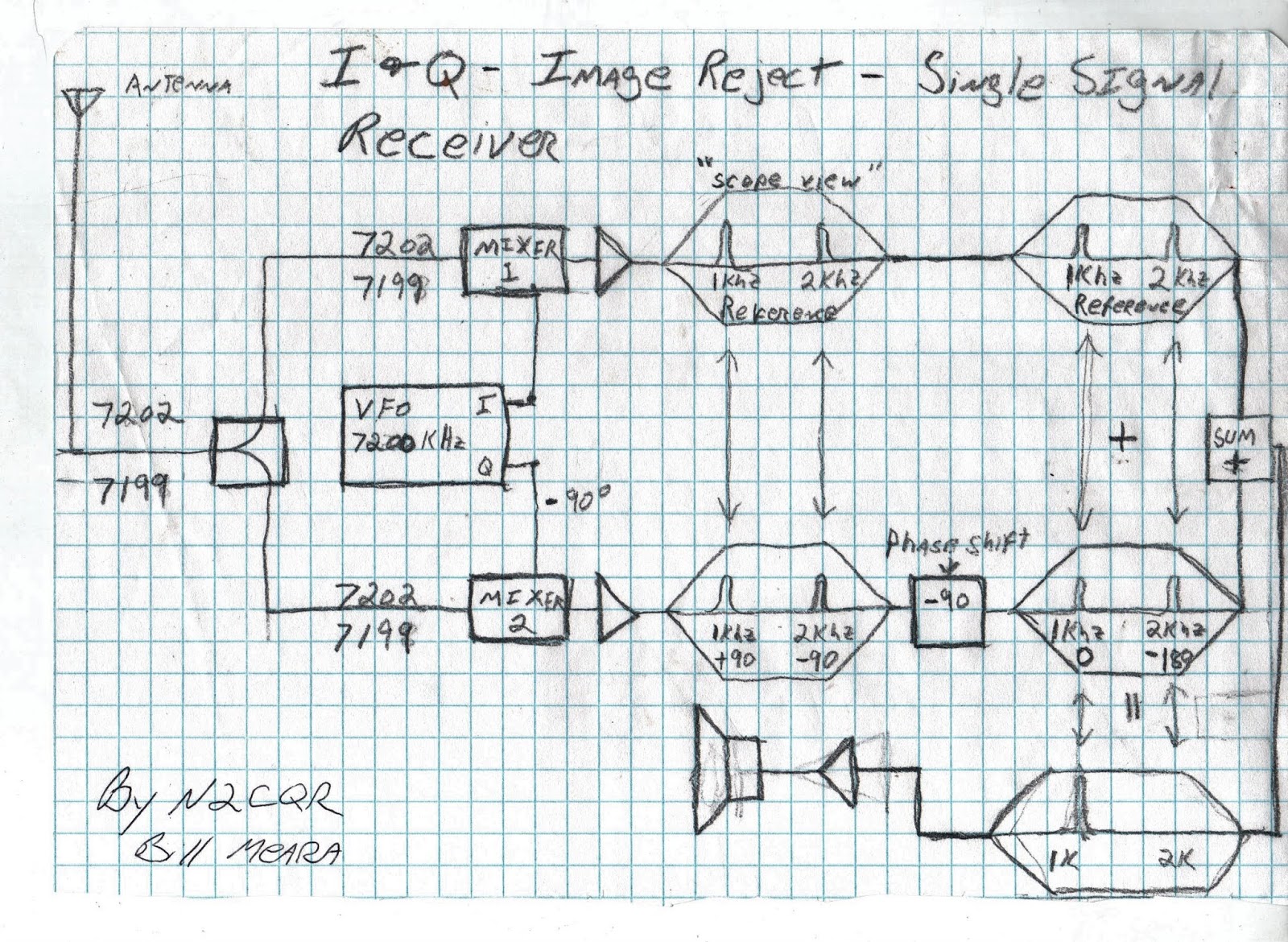
Phasing SSB
And what’s this about a tube CW rig?
SHAMELESS COMMERCE DIVISION: NEW AMAZON LINK IN THE UPPER RIGHT SIDE OF SOLDERSMOKE BLOG. .
BILL’S BENCH:
QUARANTINE PROJECT: Q-31 AM SW Receiver. April 4 through April 19. 15 days of fun. Learned a lot.
Need to pay attention to total gain. Need to measure. Not always easy. My resistor-based technique.
AM detection can be more difficult than SSB/CW detection. Germanium diodes make a big difference.
But…I don’t have to build a BFO, because these signals bring their own beat frequency.
455 CAN BE PROBLEMATIC AS AN IF – image response, making impedance matching transformers tough at those low frequencies. But WIDE filters available.
LM386 AF chip make a LOT of audio. Hard to reproduce these great results.
Great stuff you can listen to on 31 meters (9.4 –10 MHz):
n DX WaveScan
n WRMI Rock and roll
n VORW music show
n Radio Nacional De Espana (Madrid)
n China Radio International soap operas and Confucius philosophy lessons.
n China Radio International Chinese Lessons.
n Radio Greece
n Radio Republica (France)
n Radio Havana Cuba
n Radio Saudi Arabia
n WBCQ – They advised listeners to fix up an S-38 during quarantine! !!!!!!!
n WWV
SHOPPING BAG — THINGS TO GET:
— Copper Clad board: Pete’s boards use CEM 1. CEM 1 is low-cost, flame-retardant, cellulose-paper-based laminate with only one layer of woven glass fabric.
NEED/WANT:
— Thermaleze magnet wire. First encountered in QRP GUYS EFHW tuner kit. Very FB
Resistor kits
NP0 cap kit
Replacement Iron for XTRonic 4000 Iron.
RIGOL PROBES Why do we burn through so many of these?
MAILBAG:
— Eric 4Z1UG Episode 300 Special
— Farhan working on ventilators. Special thanks to Dr. Gordon Gibby KX4Z.
— Jonathan-San working out of new shed in Seattle
— WRMI likes SolderSmoke
— Peter VK2EMU continues to build his amplifier. But it is NOT for 50 MHz. It does have 6 different meters on the front panel. But it is not a 6 meter rig!
— Rich K7SZ – “now look what you’ve done” Fixing up an S-38
— Rich WD3C Provided some great SWL links:
https://www.short-wave.info/ if you move the green dot to your location it will predict what the signal strength would be at your location and will also allow you to search by station, language, frequency, etc.
— Paul KL7FLR amazing S-38E diagnosis from afar. Paul’s toroid tool (more to follow on this).
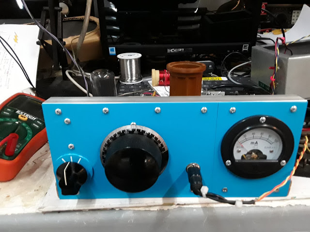 |
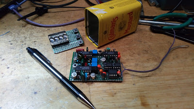
| Pete’s Quarantine 6V6 Rig |