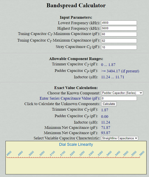
Bob’s calculator shows good tuning linearity with an ordinary SLC capacitor
One of the complaints about analog LC VFOs is that they have non-linear tuning — when you turn the dial (usually attached to a variable capacitor) the space between frequencies is NOT constant. This is especially apparent at the high end of the frequency scale where frequencies (and stations) appear to be severely bunched together, making tuning difficult. This problem contributes to the defection of some great homebrewers: They give up on LC VFOs and they switch to digital VFOs. Sad.
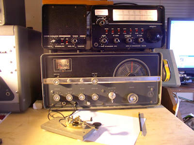
But there is hope: Not all LC VFOs tune this way. Even on rigs from “back in the day,” back when the Si5351 hadn’t even been thought of, some LC VFO rigs tuned linearly. My beloved Drake 2-B and my almost equally beloved HT-37 are good examples. How did they do this? How did they escape the dreaded “bunching up?”
For a while, I thought that it might have had to do with the use of the series tuned Clapp circuit. But on further noodling, this didn’t seem to make much sense.
Then — like others — I thought that it must be caused by the adroit use of special capacitors. You see, in ordinary variable capacitors when you turn the dial, the capacitance increases linearly. But in the LC circuit, frequency changes as the inverse of the square of the capacitance. Thus the bunching up. So the solution must come from the use of the special capacitors that compensate for this, that — because of the shape of their plates — produce linear tuning. With these variable caps, frequencies on the dial are spaced out nicely, there is no bunching up. Great right?
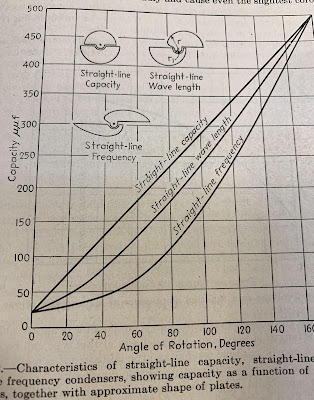
From Terman, Radio Engineers Handbook, 1943, page 123
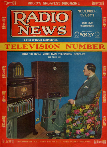
Over the years, many hams have jumped to the conclusion that rigs with good tuning linearity MUST be using these special caps. For example, in 2013 a ham posted in the Antique Radio forum this message:
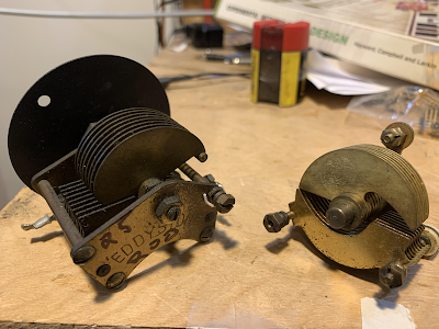
There are three types of open, variable plate caps;
SLC= straight line capacitance where the capacitance varies linearly,
these are the most common and have half-circle plates
SLF= straight line frequency where the plates are tapered to allow
for linear tuning of the frequency
SLW= straight line wavelength, you get the idea…
SLF and SLW caps have oblong plates.
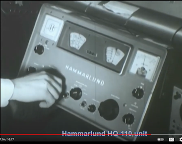
The effect on tuning a receiver can be dramatic. One example is the
Hammarlund SP series of receivers where the ham bands are very
compressed at one end of the tuning range. They used SLC caps
in the VFO. On the other hand rigs like the Kenwood TS-520
and FT-101 series have linear tuning across each band. These use
SLF variable caps. Most old 1920’s battery radios used SLW
where stations were identified by their wavelength.
Well, not really.
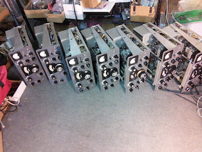
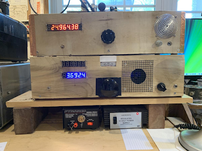
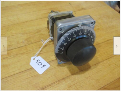
— I now have several VFOs from the extremely linear-tuning FT-101. But when you open them up to look at the tuning capacitor, it is NOT a Straight Line Frequency capacitor.
— Many of us over the years have built VFOs that are quite linear in their tuning without resort to these special capacitors — we did it with ordinary Straight Line Capacitance caps.
— When you look at the “How to build VFO” literature in the ham radio books, you see a lot of good recommendations about using solid, brass-vaned caps with ball bearings at either end. But never do you see circuits that require the use of SLF or SLH capacitors. If they were the key to tuning linearity, we’d see them mentioned in the literature. But we don’t.
So where does the linearity — or bunching up — come from?
The answer comes to us from a really neat calculator from Bob’s Electron Bunker:
http://electronbunker.ca/eb/BandspreadCalc.html
This calculator allows you to select your frequency range, and the tuning range of your variable cap. It then displays for you what the tuning range will look like on your dial. You can see if there will be bunching up, or if the frequencies will be nicely spread out. And — and this is the really cool part — you can then specify if your capacitor is SLF, SLW, SLC or Midline-Centerline. This really illustrates the effect of the different capacitor types.
I used Bob’s calculators to do some experiments with various types of capacitors, various frequency ranges, and various combinations of trimmers and padders. You can see what I did here:
http://soldersmoke.com/VariableCapsSLCSLF.pdf
One important thing to keep in mind: The SLF caps were made for AM broadcast receivers that were tuning from 540 to 1600 kc. That is a 3:1 tuning range. Most of the time in HF ham radio, we are tuning across a much smaller range, say from 5 MHz to 5.5 MHz. That is a 1.1:1 tuning range. In those cases where we ARE tuning across a wide tuning range — for example with a receiver covering 3-9 MHz, the SLF cap can help prevent the bunching up.
But we can have fairly good linear tuning without resort to SLF caps. Bob and his calculator point out that by narrowing the frequency range of interest, and by using either smaller range caps (ordinary SLC caps), or SLC caps with trimmers and padders, we can achieve tuning linearity. And sometimes, when you have achieved this nice tuning linearity with a plain SLC cap, putting a fancy SLF cap makes tuning linearity worse.
One piece of VFO tribal wisdom that is confirmed by all this: It is better to use a smaller variable cap with a maximum capacity of about 30 picofarads.
I think we should spend as much time focusing on VFO tuning linearity as we do on VFO frequency stability. Bob told me that in the old days, the calculations for various tuning linearity scenarios were difficult. But now we have Bob’s calculator. When building a VFO, just use Bob’s calculator, plugging in the numbers to get a preview of what your tuning linearity will be like. If it is bunched up, you can play with the trimmer and padder values to achieve the tuning linearity you desire.
What do you folks think of this? Please put comments below.