Recent talk of the Mate for the Mighty Midget receiver and Pete’s PIMP SSB transmitter brought me back in contact with the work of Jan, PA3GSV. I took a look at his QRZ.com page and found that he has some projects that rival even his seemingly unbeatable MMM RX project.
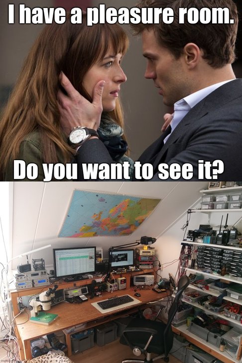
That would have been a very different movie. And I don’t think the box office results would have been favorable. That’s PH2LB’s “pleasure room” (shack). He has a good blog focused on homebrew:
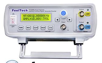
I was looking for information on my FeelTech FY3200s Signal Generator. I came across a very informative blog; it covers a variety of other Chinese gear and parts. Here is the Feeltech FY3200S article:
I really like the way Lex PH2LB measures and demonstrates the effectiveness of the Hi-Per-Mite CW filter designed by David Cripes NM0S. Watch the short video above. The blue trace is the audio input to the filter, the orange trace is the output. Watch the output change as Lex sweeps the audio frequency range. He wrote: After studying the schematic I shifting through my spare parts stock to collected the components and build one according there design on a breadboard (I changed the center frequency from 700 to 600Hz). I hooked up my signal generator with a amplitude of 2v max and sweeped it from 250Hz to 2KHz looking at the output on my rigol osciloscoop. On 2khz VMAX=0.04V, 885Hz=0.2V, 700Hz=1.5V, 662-585Hz=2V, 400Hz=0.2V, 500Hz=0.9V, 250Hz=0.04V. So a nice flat top between 585Hz to 662Hz. A full description of Lex’s project (with more videos) is here: https://www.ph2lb.nl/blog/index.php?page=ubitx-mods3#ubitx-mod14 Lex’s Knack Story and the intro to his blog is here: https://www.ph2lb.nl/blog/index.php?page=history
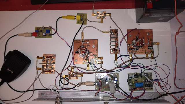
N6QW’s Simple-ceiver design is being replicated far and wide. Above you can see PA3GUP’s beautiful rig in its “Al Fresco” stage of development. For much more of this — including a cool video of Pete’s rig in action — go to Pete’s blog: http://n6qw.blogspot.com/
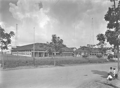
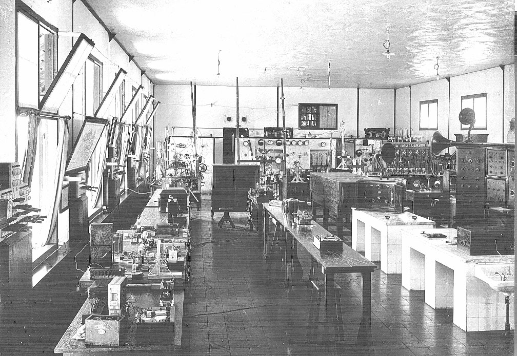
Anton PA0AST alerted me to this important piece of radio history: The first phone radio between Indonesia , the city of Bandung ( Dayeuh Kolot, Jalan Radio 1 ), and Holland , Radio Kootwijk were made in SSB already in 1927… Before that time they had only a CW 1 Mega Watt spark transmitter in Malabar. One of the receivers still exists in a museum in Amsterdam (cdvandt ). It is 3 meters in length and 2 meter in height…. All made with plug-able units with 1 tube inside . The transmitter was 10 kW. Ua was 6kV was made by dynamotors. Transmitting Tubes locally made by craftsman in a workshop. Both buildings as well in Bandung and in Kootwijk still exists . Anton The old images come from: http://www.cdvandt.org/bandung-lab-kwk.htm
At the other end was Radio Kootwijk in Holland. Before you jump to the English version of the page, be sure to check out the Drone video of the site, and the audio file of the Morse transmissions: http://radiokootwijk.nu/ Thanks to PA0JWU for the wonderful site.
Quite an impressive shack! My favorite part is the note indicating that local residents cleaned out the cooling pool and used it for swimming each summer.
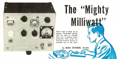
I think it is time that we get back to our QRP roots. Perhaps under the influence of the wizard of Newbury Park (N6QW), we’ve all been drifting into the world of high power. It starts innocently: you hook up a second gel cell to the IRF-510 and suddenly you are at 20 watts out from the BITX. Before you know it, you have an uncontrollable urge for 3-500Z’s. Here is a story that will get us back on the QRP track: It was September 1958. On the 14th of that month I began my first orbit of the Sun. Band conditions were VERY good. OM Don Stoner was on 10 meters with a homebrew solid-state milliwatt rig calling CQ TR, CQ TR (CQ Transistor). Jarno PA3DMI in Amsterdam sent me the link to a Radio News article by Don Stoner. The article (and the entire magazine) is a lot of fun. Check it out. The QRP fun begins on page 51. Thanks Jarno! http://www.americanradiohistory.com/Archive-Radio-News/50s/Radio-News-1958-09-R.pdf
Finally the Mate for the Mighty Midget is finished, just in time for the G-QRP Valve Day 12-13th of November.
Got the LO fixed for 40m by lowering the parallel capacitor from 150 pF to 100 pF.
Also the 68 pF series capacitor was lowered to 33 pF for some more band spread on 40m.
It now receives from about 7.0 to 7.4 MHz and from 3.45 to 4.0 MHz
Had to exchange C1 in the end, the one used initially quit every now and then.
I only had a large 3 section variable in the junk box covering 10-550 pF, which works fine now. For the lower end of 80m I had to add additional 47 pF next to the 47 pF trimmer caps, so there it is about 600-650 pF max!
At the high end of 40, it is also just not too much.
The meter was used as a position indicator for C1.
Tried several ideas, but with no separate tube for AGC, I couldn’t get it to work as a S- meter
Read something about audio derived AGC, maybe this is worth a try.
The BFO can be switched off for AM reception.
Simultaneously the input on the mixer side of the crystals is disconnected but still coupled by some capacitance of the switch wires.
AM reception is possible, but not very good.
Need to find a better solution which doesn’t degrade the crystal filter properties to much.
(By the way, the detector regen. control ads about 4 dB to the AM sensitivity)
The receiver will mainly be used for CW/SSB reception, so maybe it stays this way for a while J
I hooked it up to the W1TS transmitter, which was very loud.
Didn’t foresee a T/R relay (learned a lot from this project 😉 ), so added this one between the front plates next to the RF and audio gain control.
The quit down everything a little, the RF gain pot is lifted of ground as suggested by James, N2EY at QRZ.com.
It helped a lot, but was still too loud if tuned exactly in the bandpass of the crystals.
The T/R relay now also switches an adjustable potentiometer at the input of the audio pre-amplifier.
The dial cord has no lag, and works very well for fine tuning.
Unfortunately the reduction drive went from 1:19 to 1:9…, the tuning capacitor only has a 180 deg. span.
Something to remember for the next receiver.
It’s a nice little receiver and quite stable after warm-up.
The only extra luxury a next receiver will have, is AGC.
But with no AGC it’s easier to tune the antenna tuner by ear J
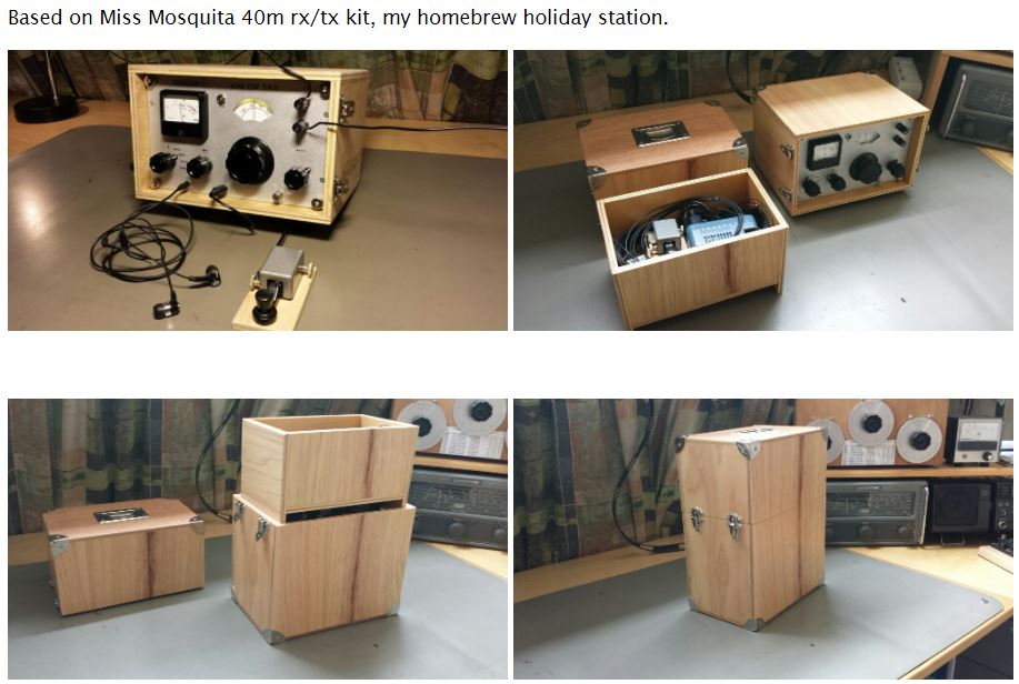
There’s now a complete homebrew station here, antenna, feeder, tuner, receiver, transmitter, power supply, al home made J
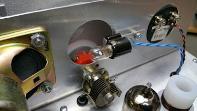
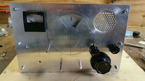
About the Mystery Hole….
If you haven’t guessed it by now, or Pete hasn’t told you, it is revealed in one of the pictures below.
Note the establishment of a new acronym (M4MMRX) for Lew McCoy’s Mate for the Mighty Midget receiver. We have needed this acronym for a long time, and SolderSmoke HQ is proud to have come up with it. We do our part my friends. Jan has made more progress on his amazing Dutch M4MMRX and has produced a short video showing the receiver in action with SSB and CW signals. Here is a bit of intriguing homebrew mystery: Jan has gone to a LOT of trouble to create that semi-circular opening in the center of the front panel. He even cut a corresponding semi-circular hole in the sewer pipe cap that serves as the large wheel in his amazing homebrew reduction drive. But he won’t tell us what he plans to do with that space. So I ask you, dear SolderSmoke readers: What is that space for? Why the see-through panel and sewer-pipe cap? What is Jan’s plan?
From Jan:
Hi Bill,
The rattle is gone, so I made a little video of the MMMRX in ssb and cw mode.
Obviously the Radio Gods (Spirits in the Sky) approve of Jan’s work. How could they not? I can now see why he took the trouble to cut that hole in the sewer pipe cap that forms the large wheel on his homebrew reduction drive. But what are we going to see through that center hole Jan? What will the frequency readout be like? ———————- Hi Bill,
Just finished the last stage of the Mighty Midget MK2.
There are first signals!
The first one I heard was a broadcast station, believe it or not, the song that was on was “Spirit in the Sky” ..
All stages were built, tested and as far as possible, adjusted separately.
It was built from back to front, so the RF amplifier was last.
I added an ECL82 for more audio, the first thought of only using an EL84 didn’t bring enough.
The triode of the ECL82 as a pre-amp, the pentode as final.
Furthermore ECF82’s were used instead of the 6U8, they’re more widely available over here.
The Miller coils are hard to come by, so the 300 uH coils are homebrew.
Also used a grid detector instead of the two germanium diodes.
The triode of V1 originally intended for audio was used for this.
Made the BFO adjustable as well, still remember the screwdriver sticking out of the coil on your side…
Happily there was not much troubleshooting needed.
The 80m coil was only 5 kHz off, the 40m coil 300 kHz (to low in frequency), still have to fix that.
Initially the receiver worked reasonably well without adjusting, but C1 quit at some point.
After some investigation, the problem was a dirty wiper contact on the rotor.
An ultrasonic bath fixed the problem, so no looking out for a replacement there. (hope it stays that way)
After adjusting, sensitivity is around -114dBm (0,4 uV) / 10 dB S/N! (with the FT241 crystals in place, and careful tuning of the controls)
Really not bad for this small receiver, Lew McCoy was right, it really is a Mighty Midget.
I wanted to make some video’s, but over here there’s a terrible S9 rattle from 160 to 15 meters.
Every now and then it appears out of nowhere, and disappears the same way.
As soon as it is gone, I’ll make some video’s.
I made one video though, just after completing the receiver.
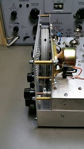
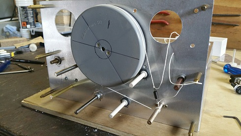
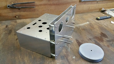
Jan sent me an amazing update on his Mate for the Mighty Midget Mk 2 receiver project. I’m really blown away by the skill that he brings to the mechanical phase of this project. This is a homebrew dial-string reduction drive using the end cap from a sewer pipe as the big wheel. Think about that. Amazing. Jan reports that with the mechanical work almost done, he is almost ready to start melting solder. FB Jan! Check out the video above and the photos below.
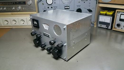
Jan is at it again, this time building a Dutch version of Lew McCoy’s Mate for the Mighty Midget. Look at front panel! But wait, there is more!
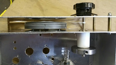
Here is a side view of the chassis. Wow. What, you may ask, is that round thing?
Holy cow! Homebrew Vernier reduction drive made from the cap of a sewer pipe. And a homebrew dial cord arrangement. Jan is clearly breaking new ground in ham radio homebrew re-purposing.
Jan writes:
Bill:
Here a little update on the MMrx.
Got almost all the parts, except for the Miller 4411 300 uH coils, for which I am attempting to make my own.
While I was looking for some pictures of this coil, if it was shielded or not (found a vintage online Miller catalogue J ),
I stumbled across this article, the W2MQ “Hamster”
There is no mention of the MMrx, but the text is very in line with the latter. Nice read.
A few days ago I received an e-mail from Jan PA3GSV — Jan is working on a receiver similar to my old Mate for the Might Midget and had some questions about how I’d handled the filter portion of the circuit. Then on Sunday, while listening to Eric’s interview with Farhan on the QSO Today podcast, I got so enthused that I felt compelled to work on a homebrew receiver. So out came the old Mate for the Mighty Midget. I built this thing in 1997-1998. It is described here:
In the above video I was listening on 75 meters to a very congenial early morning roundtable featuring W4CH, K5KBZ and others. I know, I know, this is the third or fourth video that I’ve made of this thing. This is almost as bad as 2B-mania. Or the Michigan Mighty Mite thing. I blame Jan. And Eric. And Farhan. And Grayson. And Lew McCoy!
Here is my e-mail exchange with Jan:
Bill:
I recently build the W1TS two tube xtal controlled transmitter, and am looking for a 80/40m companion for this that has a crystal filter.
At first, I wanted to build the “Simplex Super” and finally got hold of the 1700 kc crystals, but then they got lost in the mail…
Only part of a two box shipment arrived, with 455 kc fundamental frequency FT-241 crystals, so now I am looking for a diagram using a 455 kc IF. Jan
Jan: In this link you will find the schematic for the receiver I built.
I was not able to build the filter with the two 455 kc crystals. I could not obtain the needed crystals. I used two 455 kc IF transformers as described in my article. This resulted in a very broad frequency response but it was OK and quite good for AM.
Last year I put in a Toyo 455 kc SSB filter, but I did not match the impedances, so the results were not good. Your e-mail makes me want to work on this again!
Let me know how your receiver turns out.
73 Bill N2CQR
Thanks for your reply.
It is a neat looking little receiver.
And yes, I also have a cardboard box labeled “good junk” which is filled with stuff from ham fests J
Finally it will be put to good use!
I printed the article for some evening reading this week.
It will take me some time building this receiver, as there is some metalwork and mechanics involved.
I will let you know how the receiver turns out, and I am also curious what improvements you make on yours.
Thanks again, and I will let you know.
73 Jan PA3GSV
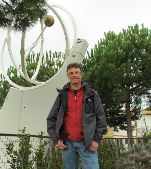
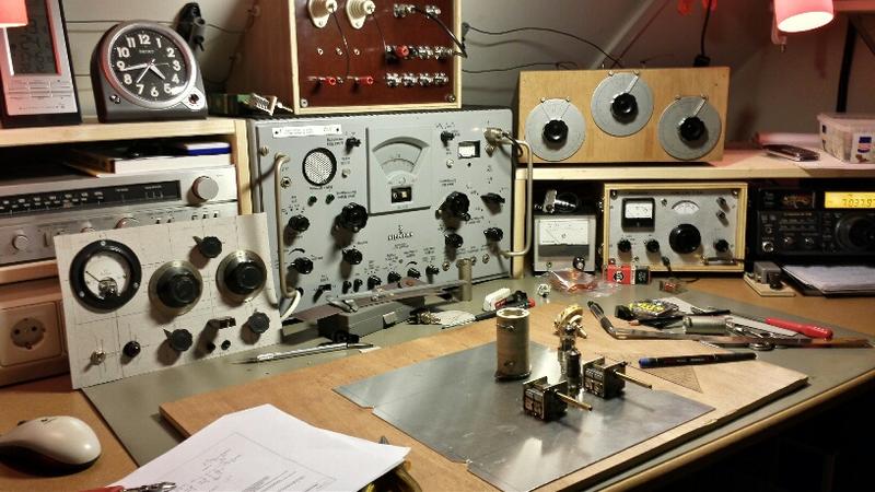
Wow, Jan has the Knack! Check out his station:
That’s the W1TS rig on the left. More pictures from Jan on his QRZ.com site. He too uses wood cabinets! I’m not alone! Here’s Jan, PA3GSV
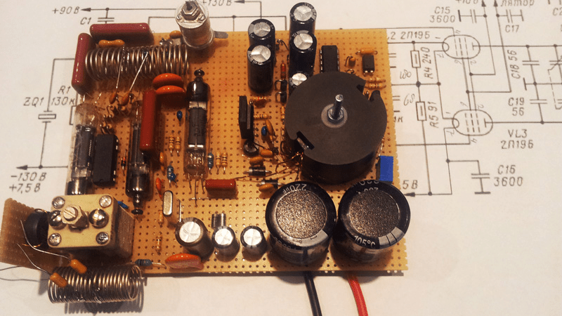
Mark K6HX pointed me to very interesting Hackaday article on Frank PA3CNO’s Sputnik transmitter replica. As blog readers will recall, we went through a period of Sputnik-mania a few years ago: http://soldersmoke.blogspot.com/search?q=sputnik Chief Designer Comrade Mikhail Rainey AA1TJ sent me some of the Russian tubes (like those pictured above).
The Hackaday article pointed to our post reporting that Oleg RV3GM had found the schematic:
http://www.radio.cc/post/Franks-power-supply-for-sputnik A mistake you say? HAH, I say! Hah! This must have been part of a sinister commie plot to prevent the capitalist imperialists from ever being able to reproduce the glorious transmitter of the Soviet people. They almost succeeded.
Just kidding.
In the course of looking through our old Sputnik posts, I came across a question I posted:
I have a question: OK so the crafty Soviets picked 20.005 MHz for some good reasons: Being so close to the WWV freq, it would be easy for hams and SWLs to find it with precision. In the November/December 2007 issue of “Break In” (from NZ — thanks Jonathan-san!) ZL3DW notes that this frequency selection would allow a receiver set to exactly 20 MHz to “produce an audio tone plus or minus the Doppler shift without ever going through zero beat.” But zero beat with what? Most of the receivers out there would not have had BFOs, right? So the Soviets wouldn’t have been using ordinary CW, right? Were they using AM, with the beeps produced by an audio oscillator modulating the carrier?
Was their diabolical plan to use WWV as the BFO for those using ordinary AM SW receivers? If so, a 5 kHz separation from WWV seems to be too much right? Especially when the Doppler shift on approach would push the frequency up a bit. Maybe they just chose this freq to make it easy for listeners to find — just a bit above WWV. Comrade Rainey surmised that they were keying the PA stage — the oscillator “backwave” was at times audible on the ground.
It’s been a while since I checked in with this site. They have made a lot of improvements. It is very impressive. I had trouble with it using Internet Explorer, but it worked right away using the Google Chrome browser. Play with it a bit. Zoom in on 40 meters. Listen to the LSB contacts. Very nice. http://websdr.ewi.utwente.nl:8901/
Bob LeDoux sent us a link to a really amazing site about the Hellschreiber system. The site is filled with great videos, pictures, and animations like the one above. Lots of radio history too. Check it out: http://www.nonstopsystems.com/radio/hellschreiber-function-operation.htm This is all the work of F. Dorenberg, N4SPP. Thanks OM!
Bob writes: I’m working on a microcontroller based reader for this mode. For old fossils, like us, this mode looks perfect. It can be sent using simple CW equipment and it appears to be a great replacement for those who are tiring of Morse code. Its perfect for Knack victims. We can even build mechanical printers. Thanks Bob!
Edwin did a beautiful job on his BITX. This is an excellent example of stage-by-stage construction. This is his THIRD BITX. On the second one he got all the parts from an old television and a washing machine. That’s the true BITX spirit! I want an S Meter! There is more information on his blog: http://pa1ed.blogspot.nl/