It kind of pains me to do this. These articles are from a long time ago, and the author is an esteemed Silent Key, but the myth about the origins of the USB/LSB convention is still out there, and as a homebrewer of SSB gear I feel obligated to point out these examples of the error that that myth is based on.
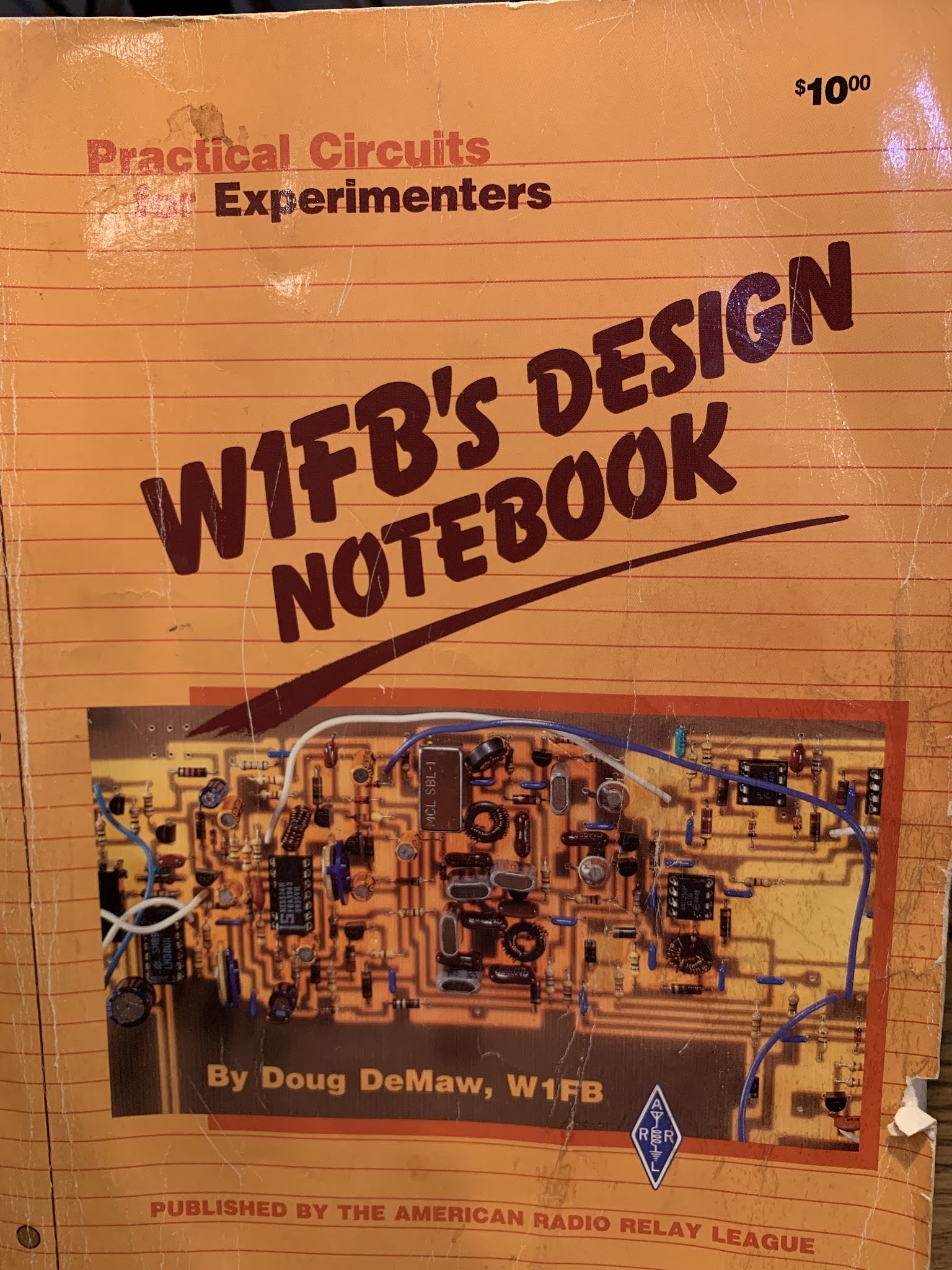
Last Friday, Pete WB9FLW and I were talking about homebrewing SSB rigs. I recommended a series of QST articles by Doug DeMaw. “Beginner’s Bench: The Principles and Building of SSB Gear” started in QST in September 1985. There were at least five parts — it continued until January 1986. (Links to the series appear below.) I hadn’t looked at these articles in years, but when I did, a big mistake jumped right out at me: In the first installment, on page 19, Doug makes the same mistake that he made in his Design Notebook:
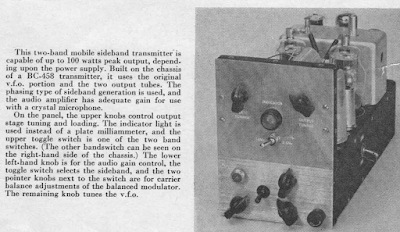
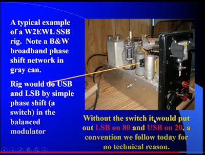
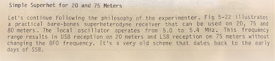
“Now comes the conversion section of our SSB generator. We must move (heterodyne) the 9-MHz SSB signal to 3.75-4.0 MHz. Our balanced mixer works just as it does in a receiver. That is, we inject the mixer with two frequencies (9 MHz and 5 MHz) to produce a sum or a difference output frequency (9 – 5 = 4 MHz, or 9 +5 = 14 MHz) If we are to generate 75 meter SSB energy, we must chose the difference frequency. We could build an 20-meter SSB transmitter by selecting the sum of the mixer frequencies. The RF amplifiers and filter (FL2) that follow would then have to be designed for 14-MHz operation. In fact, many early two-band homemade SSB transmitters were built for for 75 and 20 meters in order to use this convenient frequency arrangement. The use of upper sideband on 20 meters and lower sideband on 75 meters may be the result of this frequency arrangement (the sidebands become inverted when switching from the difference to the sum frequency.) ”
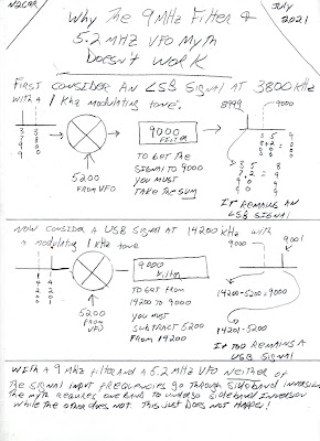
Those last two sentences are incorrect. They repeat the “Myth,” or the “Urban Legend” about the origins of the LSB/USB convention. Contrary to what many hams now believe, with 9 MHz filter and a 5.2 MHz BFO it takes more than just switching from sum frequency to difference frequency to invert one of the sidebands.
There are two conditions needed for sideband inversion to take place:
1) You have to be taking the difference product (DeMaw got that right)
2) The unmodulated (VFO or LO) signal must be larger than the modulated signal. (DeMaw and the ARRL obviously missed that part. Repeatedly.)
This is another way of stating the simple, accurate and useful Hallas Rule: Sideband inversion only occurs when you are subtracting the signal with modulation FROM the signal without modulation.
For DeMaw’s claim to be correct, one of the SSB signals going into the balanced mixer would have to invert, and the other would have to not invert. Let’s see if that happens: He has the sideband signal being generated at 9 MHz and the VFO running around 5 MHz.
9 – 5 = 4 But we are not subtracting the modulated signal FROM the unmodulated signal. SO NO INVERSION
9 + 5 = 14 We are not subtracting at all. SO NO INVERSION.
Doug’s convenient frequency scheme WOULD work if he’d just switch the frequencies of the filter and the VFO. With a sideband generator on 5.2 MHz and a VFO around 9 MHz you do get the happy 75 LSB, 20 USB arrangement without the need to switch the carrier oscillator/BFO frequency. That is what happened in the Swan 240, and that is what I have in my Mythbuster rig. I am listening to both 75 LSB and 20 USB without changing the carrier oscillator/BFO frequency. My filter/BFO/product detector is set up for USB. With this arrangement the 75 meter LSB signals DO invert, and the 20 meter USB meter signals do not, so both are able to make use of my USB BFO/product detector without shifting the BFO frequency.
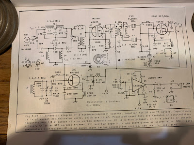
This error shows up again in DeMaw’s the May 1989 QST article “A Four Stage 75-meter SSB Superhet” (reprinted in the ARRL’s QRP Classics book). Here he writes:
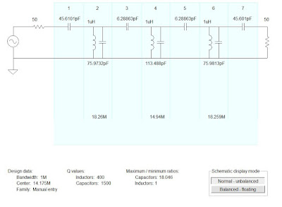
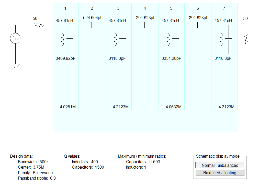
“Should you want to cover both the 75- and 20-meter bands you can build a 20-meter version of FL-1 and band switch the two filters. As with the 75 meter only version, an IF of 9.0 MHz (Y1) is required. With this arrangement the 20 meter band will tune backwards from the 75 meter band, but upper- and lower-sideband reception will occur, as required, without changing the BFO frequency (Y2). This two band scheme with a 5-MHz VFO is an old one!” NOTE: FL1 is the bandpass filter, not the IF filter.
Doug’s mistakes in this area may simply be due to the fact that he was more of a CW guy. And this is something that is quite easy to confuse: 9 and 5 will get you to 75 and 20, but you have to make sure the VFO is at 9 if you want to make use of sideband inversion and avoid having to shift the BFO/ carrier oscillator. I’ve made this mistake myself:
In October 1993 I wrote to DeMaw about his Four Stage 75 meter SSB Superhet. I think I was looking for details on how to put it on 20 meters. As I recall, Doug wrote back telling me to just pick 20 meter values for the input bandpass filter. Had I done so, I would have discovered that — for the reasons cited above — this just wouldn’t have worked on 20. His BFO and filter were set up to receive LSB signals. That’s fine for the incoming 75 meter LSB signals. But on 20 — contrary to DeMaw’s thinking — there would be NO sideband inversion. I’d be trying to listen to 20 meter USB signals with a receiver set up for 20 meter LSB.
Did anyone else notice these errors. Were there ever errata notices in QST on this?
This is a reminder that you should take all technical articles and schematics with a grain of salt. Many contain errors. We are all human, and this is a complicated subject with lots of details.