
 Caro Bill, FB on your 20mW DSB WSPR DX! I’ve never actually been on the air during the upside of a solar cycle. This is wicked exciting! Thank you for the nice write-up on your Soldersmoke Blog, OM. I heard back from Fabio this morning; he seems to be as excited as I am (please see his message below). Italy is my fourth DX contact and third country with 10mW. Two weeks ago I worked F5NBX twice and FM5LD once. Again, all great fun… I’m glad to hear of your interest in the Vladimir Polyakov’s mixer. I can attest to Vlad’s claim about its resistance to SWBCI. So far, I’ve used silicon and germanium diodes, MOSFETS, and even a saturating inductor for the subharmonic, commutating switches. I haven’t mentioned it till now, but leading up to my Gigi regenerodyne receiver, I built Polyakov reflexed 40m receiver that was lots of fun. The RF input signal first passed through a simple BPF on its way to the cathode of a triode, grounded-grid RF amplifer. The amplified signal next passed through the Polyakov anti-parallel diodes. The resulting AF signal was then re-injected into the grid of the same triode (now working as a common-cathode amplifier). In typical “reflex’ fashion, the same tube amplifies first at RF and again at AF. Looking at my notebook entry, I was able to “plainly hear” a 1.0uVrms signal and in a week of operation I hadn’t noticed any SWBC breakthrough. Actually, the subharmonic mixer was well-known by 1976, but I’d never seen it used by hams at HF until Polyakov popularized the idea. Our Eastern European comadres took a liking to it right away but it took some time before it finally caught on in the West. By the way, I had a short email exchange with Vladimir a few months ago. I’m pleased to report he’s a really nice fellow. He happened to mention that his first amateur radio transmitter was built using parts that he salvaged from an abandoned Wehrmacht tank. It seems radio components were extraordinarily hard to come by in those days. Amazing… Have fun, Bill! Mike, AA1TJ ———- Forwarded message ———- From: Fabio Ventrone Date: Sat, Mar 27, 2010 at 9:16 AM Subject: Re: IZ0PEC de AA1TJ/QRPp To: Michael Rainey Dear Michael, Many many compliments for your qrpp station! Really exciting to have qso in this conditions… It’s actually the first time I can connect qrpp oversea… Unbelievable, something we can tell our friends forever!!! I was transmitting with 4 el antenna and something more than 100w. I will have to take back my 817 and try to call dx as you bravely did!!! Best 73 qsl Fabio de IZ0PEC 2010/3/26, Michael Rainey > Dear Fabio, > > Thank you for your patience in copying my signal on 20m CW this evening. I > had been calling DX stations for several hours but you were the only one to > answer. My homebrew rig has an output power of only 10mW (0.010 watts). The > distance between us is 8793km; nearly one million km per Watt!. The antenna > here is simply an end-fed wire. > > I am amazed that you heard my 10mW signal in Rome. It’s fantastic! > > Again, thank you for patiently listening for my weak signal, OM. It would > not have been possible without your very kind efforts. > > Ciao, > Mike, AA1TJ
Category: mixer theory
Polyakov Plus! Dual-band Receiver with Subharmonic Mixer
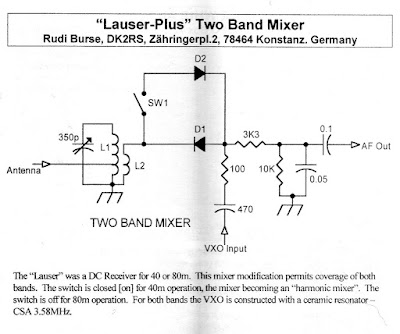 I found it! SPRAT 110, Spring 2002, page 5. A short article by OM Rudi Burse, DK2RS. This is the variation on the Polyakov Russian Mixer that I mentioned a couple of days ago. I’d been digging through piles of books and old magazines looking for this. My wife thought I’d gone nuts. (Well, nuttier than usual, actually.) It didn’t help that I responded “The Polyakov Russian sub-harmonic mixer circuit with two band application!” when she asked what I was looking for. Of course, I should have known that it was in SPRAT. It just happened that the issue with this article was piled under a lot of junk on the workbench. I really like this circuit. Ingenious. And now that I have come to understand mixers a bit better, I can appreciate this one more. Here’s how I’d explain it: With the switch closed, the signal from the LO “opens” one of the diodes on the positive peak, and it opens the other diode on the negative peak. So that RF signal from the antenna is getting sampled and mixed twice each cycle of the LO. The resulting complex waveform has sum and difference frequencies of RF+2LO and RF-2LO. With the switch open, you only have one diode sampling the RF, and it opens only ONCE each LO cycle. So the complex waveform that comes out of this single diode had frequencies of RF+LO and RF-LO. This opens the possiblity of DC receivers for 80/40, 40/20, 20/10 meters, etc. I guess a key adjustment in this circuit would be getting the LO level just right. Thanks SPRAT! Thanks Rudi! Thanks Vladimir Polyakov!
You’ll see in the comments attached to my last blog post that our man on the left coast, Steve Smith, gave that cute little Doug DeMaw/Vlad Polyakov receiver a name that might set American-Russian hamrelations back a bit: He called it “Vlad The Inhaler.” Good one Steve! (But you might want to stay out of the diplo game!)
Check out “SolderSmoke — Global Adventures in Wireless Electronics” http://soldersmoke.com/book.htm
Polyakov’s Russian Mixer
 I’m planning on building a DC receiver for use with the WSPR system. I will probably follow W3PM’s lead and put a crystal filter between the antenna and the mixer. This will be a fixed frequency receiver aimed at one 200 hz slice of the 30 meter band.
Of course, the big question is what mixer circuit I should use. I’ll probably go with an SBL diode ring, but while perusing the literature, I again came across “The Russian Mixer” of Vladimir Polyakov, RA3AAE. Michael, AA1TJ, is a big fan of this circuit, and has been talking about it on Radio Havana Cuba. What a cool circuit it is! Just two diodes in parallel, cathode to anode. RF from the antenna goes in one side, and the local oscillator signal is placed at the other end. The LO signal causes the diodes to turn on and off on voltage peaks, effectively chopping up the incoming signal, producing sum and difference frequencies. LA8AK’s drawing of one version of this circuit appears above. (Obviously OM AK didn’t like this configuration, but it gives you the idea.)
The really cool part is that because you have two diodes, the “chopping” takes place at TWICE the LO frequency. This happens because on a positive LO peak one of the diodes conducts, and then, on the negative peak, the other conducts. So it is as if the mixer gate is opening twice each LO cycle. This allows you to run the oscillator at half the operating frequency, with advantages for stability and for the effort to eliminate common mode hum.
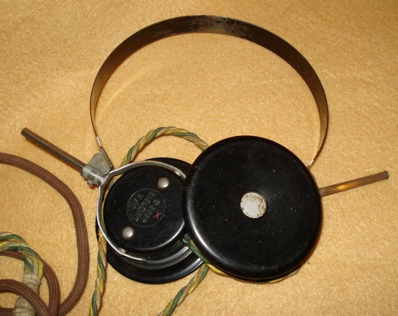
A while back I saw (somewhere!) a clever use of this circuit. LO was running at around 3.5 Mhz. With the two diodes in the circuit, it was a 40 meter receiver. They had a switch that could remove the second diode from the circuit. By throwing this switch, the RX went to 80 meters.
Does anyone remember this circuit? Where did it appear? SPRAT? QQ? Tech Topics? I can’t find it.
I had the impression that OM Polyakov was active in the early days of radio. But some Googling shows that he is of much more recent vintage, still active and listed on QRZ.com. Here he is:
QRP Quarterly — Winter 2010
 Lots of great stuff in the latest edition of QQ from QRP ARCI:
Mike Czuhajewski’s “Idea Exchange” column has been sending out great ideas for many years now. In this edition he opens with a piece from Wes, W7ZOI, that originally appeared on the EMRFD mailing list. It deals with diode ring mixers, specifically the power requirements for the local oscillator. What do they really mean when they specify 7 dBm? Wes explains: “If we say that the LO power is +7 dBm, what this really means is that a signal generator is attached to a power meter or spectrum analyzer and adjusted to deliver +7 dBm at the desired frequency to the 50 ohm instrument. Once the power is set, the cable is disconnected and reattached to the mixer.” I’d always wondered about how to measure that. Thanks Mike! Thanks Wes!
Preston Douglas, WJ2V, has a nice article on our latest craze: WSPR. Preston also discusses SDR radios — his encouraging comments may help me get out of my current luddite curmudgeon rut. Preston mentions recent efforts to use a BITX-20 for WSPR and concludes that this would be “a tall order for any analog rig.” This comment lessened my feelings of inadequacy about my SDR SMT problems, because I recently used my ancient Drake 2-B to receive WSPR sigs (see earlier blog entry). Luddites Rule! But Preston is right — it’s not easy! But — at least for a little while, before drift takes you out of the band — it can be done.
Ward Harriman, AE6TY, writes of a “homebrew” SDR project. In his opening paragraph, he tells us what the term “homebrew” means to him: “homebrew design, homebrew assembly, homebrew programming, homebrew in a wide range of disciplines both familiar and untried.” That’s pretty hardcore! FB Ward!
Jim Osburn, WD9EYB, has a nice article on “circuit stickers” and how they can be used to simplify project construction using a variety of circuit boards and breadboards. I really liked Jim’s description of old Electronics Illustrated projects in which they pasted a diagram to a wood base and then put finishing nails at specified points. Components were then soldered to the finishing nails. When the thing works, you can say you “really nailed it!” (Sorry!) Cool technique.
Thanks to the folks at QRP ARCI for another inspiring edition of their wonderful magazine. If you are not a member, you are missing a lot. Sign up for the club and the magazine here:
http://www.qrparci.org/
Does Math Lead to Understanding?
 In “SolderSmoke — The Book” I describe the quest for deep understanding of the circuits that we build and use. There is some discussion in the book of the role of mathematics in this quest. A while back a reader e-mailed me on this subject. In the hope of stimulating a discussion, I’ll present the key paragraph from that e-mail here (the author will, for now, remain anonymous):
I appreciate your quotes from Feynman, Asimov, etc. about not
really being able to fully understand everything. As a math teacher
I can say that one of the biggest misunderstandings about math
is that it “explains” the phenomena of physics and engineering.
(Science and math teachers are notorious for saying to a student
who has just asked a “why” question things like, “well the math is
a little bit more complicated than what you can handle right now.
Wait untilyou have had a year or so of calculus.”) In reality it’s
the exact opposite! The math equations actually hide the answers.
They are very good at accurately describing phenomena, or at
predicting what will happen next, but they can never answer the
question of why one equation works and another does not. We
get very comfortable with allowing the familiar math equations
to hide our inability to really answer the “whys.”
This really resonated with me. In my effort to get a better grasp of mixer theoy a lot of people seemed to be simply pointing me to the trig equations, and equating a knowledge of those equations with an understanding of how the mixer circuits really work.
Of course, I don’t mean to be anti-math here, but I thought the e-mail on the limits of mathematics was very interesting. In “Empire of the Air” Tom Lewis wrote, “At Columbia, Edwin Howard Armstrong developed another trait that displeased some of the staff and would annoy others later in life: his distrust of mathematical explanations for phenomena of the physical world. All too often he found his professors taking refuge in such abstractions when faced with a difficult and seemingly intractable conundrum… Time and again as an undergraduate at Columbia, Armstrong had refused to seek in mathematics a refuge from physical realities.”
A Fondness for Phasing
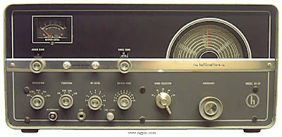
As the proud owner of a Hallicrafters HT-37, I have long had a fondness for phasing rigs. It took me a long time to figure out exactly how they manage to drop the carrier and one of the sidebands without the use of crystal filters. This was one of the technical understanding battles of my radio youth, and is detailed in SolderSmoke — The Book. (See the upper part of the right column of this blog for details on how to get the book.)
I was reminded of all this by a link sent in by Jim, AB3CV. It is an EDN design note, and describes a simple modern SSB generator using two phasing networks, three IC’s, and a handful of discrete components:
http://www.edn.com/contents/images/93099di.pdf
Mixing it up
OK, enough of the pretty pictures from outer space, now it’s time to go back to mixer math.
In the podcast, on this blog, and in the SolderSmoke book I have chronicled my efforts to understand how mixer circuits REALLY work. For some of us, the trig is just not enough. We want intuitive understanding. Ya’ gotta draw us a picture. Mike KC7IT, and Dennis W6DWF, both alerted me to a good one. It is from a new book “RF Front-End: World Class Designs”, Edited by Jane Sullivan Love. The chapter on mixers is available online here:
http://i.cmpnet.com/rfdesignline/2009/08/C0429pt1.pdf
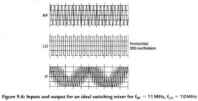 I really like figure 9.6 (above). You can really SEE how the switching action that is driven by the LO kind of “chops up” the RF signal and produces the complex waveform that is the IF. The neat thing about the IF waveform in this drawing is that you can clearly see both the sum freq (the smaller squiggles) AND the difference freq (the overall movement inside which the smaller squiggles are present). Go ahead, count them up! Sums and differences!
This is a special kind of mixer: a polarity-reversing switching mixer. When the LO is negative, it inverts whatever is at the RF port. From this you can see why mixers are described mathematically as “multipliers.” This mixer is multiplying the instantaneous value of the RF input by +1 (when the LO is positive) and then by -1 (when the LO is negative).
I think it is quite a bit harder to “see” the genesis of the sum and difference freqs when you are working with non-switching mixers, but this diagram is, I think, really useful in gaining an intuitive understanding of what goes on in the mixing process.
Inside a Mini-Circuits Mixer, and the Dissing of DSB
 I’m not crazy about using integrated circuits, especially the really complex ones for which true understanding of how they work is impossible. The Mini-Circuits mixers are not, of course ICs, but for me they too have always had a whiff of the “black-box” about them. Thomas, OZ2CPU, pulls away the veil with this photo of the innards of an SBL-1.
I came across Thomas’s very interesting web site when I was installing in my QRSS beacon rig the SBL-1 mixer sent to me by Jim, AL7RV. That poor SBL had died suddenly during testing. Thomas alerted me to the cause of death: In his caption for the picture of the innards, he notes, “I was unlucky to kill this one during my first transmit experiment. The IF input can NOT accept more than +20dBm audio level.”
 Joop and I have been discussing diode ring mixers, and I’ve been reading an article about them by Paul, NA5N. It looks to me like the designers of the SBL mixers weren’t really thinking of balanced modulators when they created these things. Just look at the schematic above. In a normal receiver application, LO energy goes in from the L port, your RF goes in R, and your IF (or, in a DC receiver, your AF) comes out from the I port. But when we use these things as balanced modulators, we have to put the Audio INTO the I port. You can see how too much voltage on that port would quickly release the smoke from those little hot-carrier diodes.
The data sheets are oriented to the standard application (RF into R, LO into L, IF output at I). We are told to keep the LO level at +7dBm and that the 1 db compression point for the RF input is +1dBm. But at what level should you put the AF input to the I port if you are using this thing as a balanced modulator in a weird WSPR DSB rig? Similarly, the data sheets give SWR data across a wide frequency range for the L and R ports… but not for the I port. DSB is getting dissed!
Are Diode Ring Mixers Fundamentally Different?
 Joop, PE1CQP, and I have been discussing mixer circuits, especially the ever-popular diode ring.
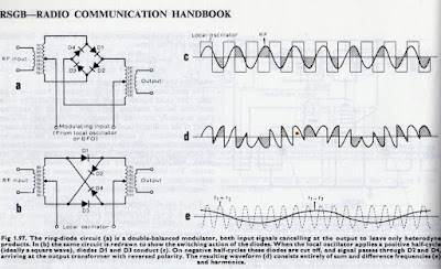
Here is my latest e-mail to Joop. The RSGB diagram for the ring diode mixer appears above.
Joop: I think the way the diode ring mixer works is very different from the way a two diode singly balanced mixer functions. The effect, of course, is the same. But the polarity reversing element introduced by the ring configuration — it seems to me — makes this a very different circuit.
Attached is the RSGB Handbook diagram I mentioned. I like it, because you can really SEE how the actions of the diode ring produce the sum and difference freqs (you have to keep Fourier in mind, and imagine the results of filtering).
The two diode circuit simply “chops” the input signal at the rate of the LO. And it would even work in a non-switching mode — you could, for example, use FETs instead of the diodes and bias them to operate in the non-linear portion of their curves, right? This makes me think that the diode ring mixer circuits (aka “polarity switching mixers” or “commutating mixers”) are very different.
73 Bill