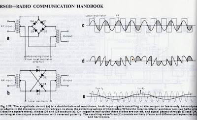
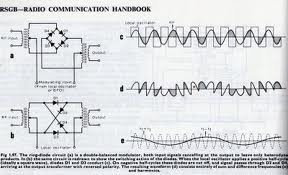
You know that you are sinking deep into The Knack when you watch a video like this one and find yourself thinking: “FANTASTIC! WOW! Now I know why square waves are better!” I really liked this one. In the beginning I was kind of concerned about his refusal to explain how non-linear, non-switching mixers work. He actually used the dismissive non-explanation that I’ve always found so disappointing: “Blah, blah, blah… it’s in the trig.” And he actually said, “Blah, blah, blah.” But he more than made up for it when he got into the switching mixers. Note that his drawing (at the start) of “Mixing by Switching” attempts to show the waveform that results from an LO “chopping up” an incoming RF signal. I always find that picture worth a thousand trig equations.
I also really liked his explanation of the benefits of rapid rise time in switching mixers, and how slow switching causes the diodes to spend some time in the non-linear part of their curves, giving rise (!) to IMD products (I’m paraphrasing). You can really see why they say it is better to drive diode rings with square waves. So stop trying to put low pass filters between your LO and the diode ring. Square waves are your friends here.
Mr. Marki seems to be one very cool EE. And I’d like to hear more about his dad. Here is some more about the Marki engineers:
http://mwexpert.typepad.com/markimicrowave/