January 2, 2008 SPECIAL NEW YEAR’S EDITION AA1TJ’s circuitry and poetry. Homemade tubes. Book Review “Early Radio” by Peter Jensen. The Vatican’s antennas. Google Earth flight simulator. Mixer madness continues (now in LTSpice). Mars-asteroid collision? Bollywood: The BITX-20 connection. BANDSWEEP: Straight Key Night at WA6ARA. ECHO-GUEST: Andy, ZS6ADY, South African Boatanchor fan. MAILBAG: Jake N4UY(NOVA QRP), Steve G0FUE (Bath Build-a-thon), Nigel M0NDE
Category: mixer theory
Vasily Ivanenko on Vladimir Polyakov’s Subharmonic Detector
Our old friend “Vasily” sent in a very insightful comment about the Polyakov receiver. It was so good that it merits a blog post of its own. Here it is. Thanks Vasily!
Vasily IvanenkoAugust 9, 2022 at 12:49 AM
Thanks Bill. My own experiments at HF with subharmonically pumped Schottky diode mixers show clearly that almost every mixer parameter we measure is worse than our classic balanced mixer topologies. Definitely 2LO-RF isolation was better than other unbalanced mixers without the need for a transformer.
I guess it’s appealing for low-complexity receiver builders. For zero IF receivers, I like and run my LO at 1/2 RF frequency and then use a doubler — that’s a great advantage for
a DC/ Zero-IF receiver and a built-in feature for the subharmonic mixer.
The SH mixer becomes quite appealing at SHF to mm-wave lengths where making a quiet, temp stable LO gets rather expensive and tricky.
Subharmonically pumped mixers can also work at odd integers if the mixer LO/RF drive is balanced and designed to produce distortion that for example, triples the LO frequency. Rohde & Schwarz had a 40.1 GHz spectrum analyzer with one — and if the LO was 13 GHz while the RF was 39.5 GHz, this gave an IF output of 500 MHz in 1 particular circuit. Really amazing design work. Here’s an interesting URL:
https://www.eravant.com/products/mixers/subharmonically-pumped-mixers
The SH mixer has been around for > 4 decades. The oldest SH mixer paper I’ve got in my library is from Schneider and Snell from 1975. I don’t think they invented the SH, but this pair helped popularize it for the world and design work continues today.I’ve seen optical SH mixers with I/Q outputs in research papers.
Here’s the abstract and citation:
Harmonically Pumped Stripline Down-Converter
M. V. Schneider, W. W. Snell
Published 1 March 1975
Physics, Engineering
IEEE Transactions on Microwave Theory and Techniques
A novel thin-film down-converter which is pumped at a submultiple of the local-oscillator frequency has given a conversion loss which is comparable to the performance of conventional balanced mixers. The converter consists of two stripline filters and two Schottky-barrier diodes which are shunt mounted in a strip transmission line. The conversion loss measured at a signal frequency of 3.5 GHz is 3.2 dB for a pump frequency of 1.7 GHz and 4.9 dB for a pump frequency of 0.85 GHz. The circuit looks attractive for use at millimeter-wave frequencies where stable pump sources with low FM noise are not readily available.
Best to you!
Polyakov Direct Conversion Receiver on 80 Meters (video)
In today’s episode I put the switch in the open position turning the receiver into an ordinary Direct Conversion receiver with a single diode as the detector. I find that it works pretty well on 80, but probably not as well as it does on 40 (where it is in full Polyakov mode). (Yesterday I demonstrated the receiver in action on 40 and provided details on the circuit. See: https://soldersmoke.blogspot.com/2022/08/polyakov-ra3aae-direct-conversion.html)
You will notice that when I throw the switch, but before I retune the input LC network, you can still hear the signal from the previous band. So when I have it in 40 and I throw the switch to open, you can still hear the 40 meter signal. Apparently one diode will (poorly) demodulate a signal with the VFO running at HALF the operating frequency. I saw this in the real world receiver and also saw it in an LTSpice simulation. In LTSpice the signal level drops significantly when I go to just one diode: From 50 mv peak to 15 mv peak, but it can still be heard. Something similar happens when I go from 80 to 40. When I close the switch and suddenly have two diodes and a 3.5 MHz VFO trying to demodulate the 80 meter signal, I can still hear the 80 meter signal, but it is much weaker and a lot more noise is getting through. Again, I saw this in the real world and in LTSpice. It looks as if with the two diodes, the 3.5 MHz signal is being sampled twice each VFO cycle. This may result in some output in the audio range. But again, it is much weaker.
SolderSmoke FDIM Interview with Keith W. Whites — Teaching Electronic Design to EE students using a QRP Transceiver designed by Wayne Burdick
I told Keith Whites that I had struggled to understand the Gilbert Cell and the NE602, the device that lies at the heart of the rig used in both courses: The NE-602 Gilbert Cell Mixer used in Wayne Burdick’s NORCAL 40A. Here is how I came to understand the device: https://soldersmoke.blogspot.com/2021/11/how-to-understand-ne-602-and-gilbert.html
Here is Bob Crane’s interview: http://soldersmoke.com/2022 Whites.mp3
Here the slides that Keith used at FDIM: http://soldersmoke.com/2022 Teaching NorCal40A.pdf
Keith’s students obviously got a lot out of this course. Keith has kindly offered to make his course notes available to those who need them.
Thanks to Bob Crane, Keith Whites, David Rutledge and Wayne Burdick.
Putting a Barebones Superhet on 17 Meters with an NE602 Converter (Video)
How To Understand the NE-602 and the Gilbert Cell Mixer
W2EWL’s “Cheap and Easy SSB” Rig — And The LSB/USB Convention Myth
In March 1956 Tony Vitale published in QST an article about a “Cheap and Easy” SSB transmitter that he had built around the VFO in an ARC-5 Command Set transmitter. Vitale added a 9 MHz crystal-controlled oscillator, and around this built a simple phasing generator that produced SSB at 9 MHz. He then made excellent use of the ARC-5’s stable 5 – 5.5 MHz VFO. His rig covered both 75 meters and 20 meters. Here is the article:
Because it used the 9 and 5 frequency scheme, over the years many, many hams have come to think that Vitale’s rig is the source of the current “LSB below 10 MHz, USB above 10 MHz.” This is wrong. An example of this error popped up on YouTube just this week (the video is otherwise excellent):
QST Recognized Error on Sideband Inversion, But Continued to Make the Same Mistake
A Video Series on the Mythbuster 75/20 Rig — Video #1
Farhan’s sBITX — Combining SDR with the Traditional Superhet
The SST QRP Transceiver
https://qrpbuilder.com/wp-content/uploads/2017/04/sst_manual_042217.pdf
HRDX Interviews Paul Taylor VK3HN
AA7EE Casually Kills a Direct Conversion Receiver, then Coldly Discards a Diode Ring Mixer
I was really glad to see that Dave AA7EE has — after a long absence — posted another article on his blog. The article has some great personal reminiscences about his involvement with direct conversion receivers. Here is one passage:
I spent many happy hours tuning around and listening on 80M with the DSB80. It was this first experience that cemented my affinity for direct conversion receivers built with commercially available diode ring mixer packages. It just seemed so simple – you squirt RF into one port, a VFO into the other, and (after passing the result through a diplexer) amplify the heck out of the result. The seeming simplicity of the process of converting RF directly to baseband audio has held great appeal for me ever since. Unfortunately, that project didn’t survive. One day, in later adulthood, in my apartment in Hollywood, I reversed the polarity of the 12V DC supply and, discouraged at it’s subsequent refusal to work, tossed the whole thing away. Now, I cannot quite believe that I did that, but it was during a long period of inactivity on the ham bands, and complete lack of interest. If only I could go back, and not have thrown it into the dumpster of my apartment building! Hollywood is ridden with recent notable history. My little double sideband transceiver met it’s unfortunate end just 100 feet from the spot where Bobby Fuller, of The Bobby Fuller Four, was found dead in his car, in 1966, the subject of a still unsolved mystery to this day. The death of my little DSB rig was a lot less mysterious. To think that I heartlessly tossed an SBL-1 mixer into a dumpster, is a mark of how far I had strayed from my homebrewing roots, forged in a little village in England. Now, a few years later, in a city known for it’s sin and excess, I had cruelly ended the life of a stout and honest diode ring mixer. I suppose I should spare a thought for the polyvaricon but, well, you know – it was a polyvaricon!
https://aa7ee.wordpress.com/2021/03/04/the-ve7bpo-direct-conversion-receiver-mainframe/
Phasors and the Propeller Analogy from Walla Walla University
Some Thoughts on Singly Balanced Mixers with Two Diodes and One Transformer
In 2001, out it in the Azores, I built a 17 meter version of Doug DeMaw’s Double Sideband transmitter (“Go QRP with Double Sideband” CQ Magazine, February 1997). I struggled to understand the balanced modulator — how it mixed, balanced, and how it produced DSB. I later presented my understanding of the circuit in my book “SolderSmoke — Global Adventures in Wireless Electronics” pages 132-137. In essence, I figured out that you had to think of the balancing and the mixing as two separate operations: The transformer provided the balance that eliminated the carrier (the LO signal) while the diodes presented the two signals (audio from the mic amp and LO from the VFO) with a highly non-linear path. The LO was successively turning on both diodes then turning off both diodes. The audio signal was being “chopped” at the rate of the LO. This produced a complex waveform that contained sum and difference frequencies — the upper and lower sidebands. The carrier was balanced out by the transformer because the two outputs of the transformer were always of opposite polarity, and they were joined together at the output of the mixer.
So Many Wonderful Things on W7ZOI’s Site
There he is. Wes Hayward, W7ZOI in 1957. I had never seen this picture before. I found it on Wes’s recently updated “shackviews” web page: http://w7zoi.net/shackviews.html .
There are so many treasures on that page, and on all the other portions of Wes’s site.
Some highlights for me:
— Wes’s description of the station in the above picture.
— On his page about Doug DeMaw, Wes mentions that after Doug edited Wes’s 1968 article about direct conversion receivers, Doug built some himself, experimenting with different product detector circuits. Having used Doug’s mixer circuit in many of my rigs, and having recently experimented with different product detectors for my HA-600A, I kind of felt like Doug was watching over my shoulder, guiding me along as I experimented.
— Wes’s use of a digital Rigol oscilloscope. Makes me feel better about giving up on my Tek 465.
— The page about Farhan’s visit to Wes, and the awesome gathering of homebrew Titans that ensued…
— Wes’s meeting with Chuck Adams.
Thanks Wes. Happy New Year and best of luck in 2021!
SolderSmoke Podcast #227: Solar System, SDR, Simple SSB, HA-600A, BITX17, Nesting Moxons? Mailbag
Mars is moving away. Jupiter and Saturn close in the sky. And the Sun is back in action – Cycle 25 is underway. Also, the earliest sunset is behind us. Brighter days are ahead.
Book Review: “Conquering the Electron” With a quote from Nikola Tesla.
No real travel for us: Hunkered down. Lots of COVID cases around us. Friends, relatives, neighbors. Be careful. You don’t want to be make it through 10 months of pandemic only to get sick at the very end. SITS: Stay In The Shack.
Pete’s Bench and Tech Adventures:
Backpack SDR keithsdr@groups.io
Hermes Lite 2
Coaching SSB builders
G-QRP talk
A new source for 9 MHz crystal filters
Bill’s Bench:
Fixing the HA-600A Product Detector. Sherwood article advice. Diode Ring wins the day. Fixing a scratchy variable capacitor. Studying simple two diode singly balanced detectors. Polyakov. Getting San Jian frequency counter for it.
Fixing up the 17 meter BITX. Expanding the VXO coverage. Using it with NA5B’s KiwiSDR.
Resurrecting the 17 meter Moxon. But WHY can’t I nest the 17 meter Moxon inside a 20 meter Moxon? They do it with Hex beams. Why so hard with Moxons? DK7ZB has a design, but I’ve often heard that this combo is problematic. Any thoughts? I could just buy a 20/17 Hex-beam but this seems kind of heretical for a HB station.
Suddenly getting RFI on 40 meters. Every 50-60 Hz. Please tell me what you think this is (I played a recording).
MAILBAG:
Dean KK4DAS’s Furlough 40/20
Adam N0ZIB HB DC TCVR
Tony G4WIF G-QRP Vids. Video of George Dobbs.
Grayson KJ7UM Collecting Radioactive OA2s. Why?
Pete found W6BLZ Articles
Rogier KJ6ETL PA1ZZ lost his dog. And we lost ours.
Steve Silverman KB3SII — a nice old variable capacitor from Chelsea Radio Company.
Dave K8WPE thinks we already have a cult following.
Dan W4ERF paralleling amps to improve SNR.
Jim W8NSA — An old friend.
Pete Eaton WB9FLW The Arecibo collapse
John WB4GTW old friend… friend of:
Taylor N4TD HB2HB
And finally, we got lots of mail about our editorial. No surprise: Half supportive, half opposed. Obviously everyone is entitled to their opinion. And we are free to express ours. It’s a free country, and we want it to stay that way. That is why we spoke out.
Yesterday the Electoral College voted, finalizing the results. All Americans should be proud that the U.S. was able to carry out a free and fair national election with record turn out under difficult circumstances. And all loyal Americans should accept the results. That’s just the way it works in a democracy.
We are glad we said what we said. It would have been easier and more pleasant to just bury our heads in the sand and say nothing. But this was a critically important election and we felt obligated as Americans to speak out. We’d do it again. And in fact we reserve the right to speak out again if a similarly important issue arises.
Wrapping up the HA-600A Product Detector Project — Let’s Call Them “Crossed Diode Mixers” NOT “Diode Rings”
This has been a lot of fun and very educational. The problem I discovered in the Lafayette HA-600A product detector caused me to take a new look at how diode detectors really work. It also spurred me to make more use of LTSpice.
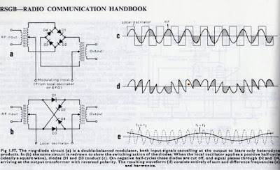
In the end, I went with a diode ring mixer. Part of this decision was just my amazement at how four diodes and a couple of transformers can manage to multiply an incoming signal by 1 and -1, and how this multiplication allows us to pull audio out of the mess.
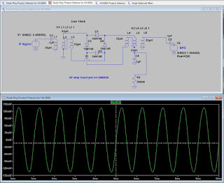
But another part of the decision was port isolation: the diode ring mixer with four diodes and two transformers does keep the BFO signal from making its way back to into the IF chain. This helps prevent the BFO signal from activating the AGC circuitry, and from messing up the S-meter readings. LTSpice helped me confirm that this improvement was happening: in LTSpice I could look at how much BFO energy was making its way back to the IF input port on the diode ring mixer. LTSpice predicted very little, and this was confirmed in the real world circuit. (I will do another post on port isolation in simpler, singly balanced diode mixers.)
At first I did have to overcome some problems with the diode ring circuit. Mine seemed to perform poorly with strong signals: I’d hear some of the “simultaneous envelope and product detection” that started me down this path. I also noticed that with the diode ring, in the AM mode the receiver seemed to be less sensitive — it was as if the product detector circuit was loading down the AM detector.
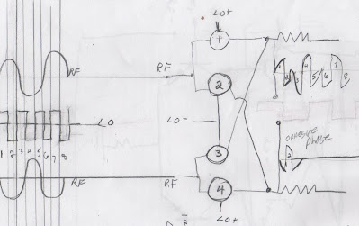
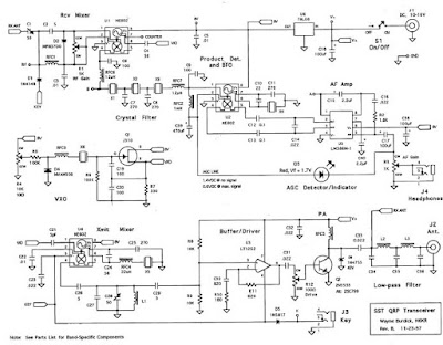
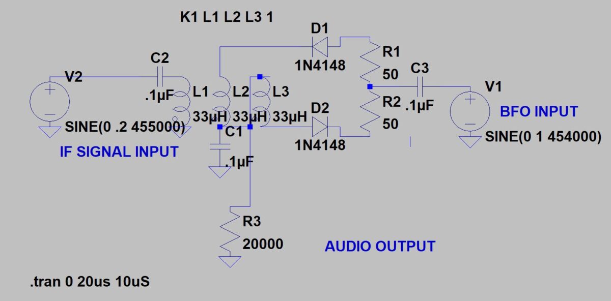
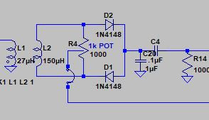
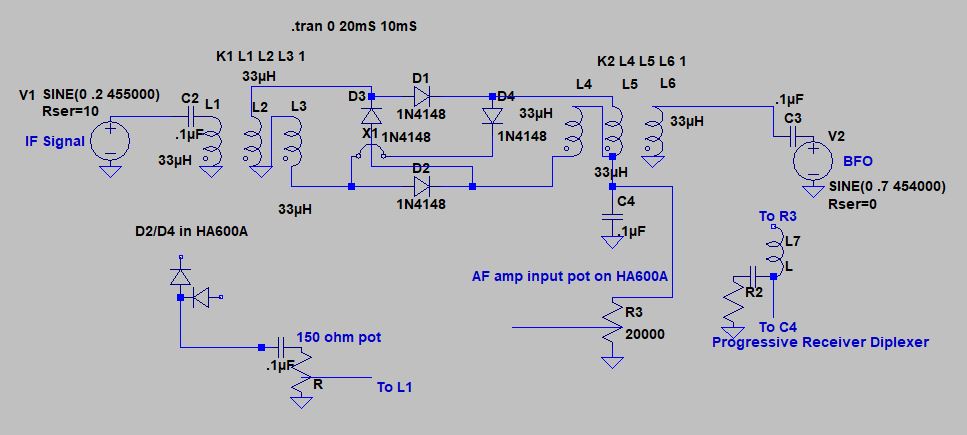
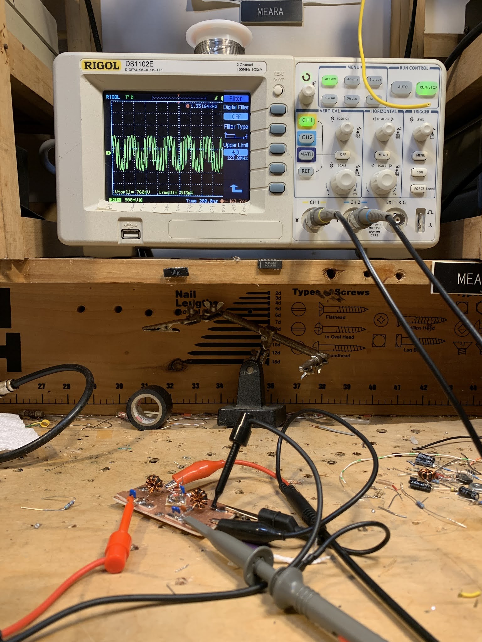
One of the commenters — Christian — suggested putting some resistance into the input of the diode ring circuit. I put a 150 ohm pot across the input, after the blocking capacitor. The top of the pot goes to the capacitor, the bottom to ground and the wiper to the input of L1 in the diode ring circuit (you can see the circuit in the diagram above). With this pot I could set the input level such that even the strongest input signals did not cause the envelope detection that I’d heard earlier. Watching these input signals on the ‘scope, I think these problems arose when the IF signals rose above .7 volts and started turning on the diodes. Only the BFO signal should have been doing that. The pot eliminated this problem. The pot also seemed to solve the problem of the loading down of the AM detector.
With the pot, signals sounded much better, but I thought there was still room for improvement. I thought I could hear a bit of RF in the audio output. Perhaps some of the 455 kHz signal was making it into the AF amplifiers. I looked at the circuit that Wes Hayward had used after the SBL-1 that he used as product detector in his Progressive Receiver. It was very simple: a .01 uF cap and 50 ohm resistor to ground followed by an RF choke. I can’t be sure, but this seemed to help, and the SSB now sounds great.
A BETTER NAME?
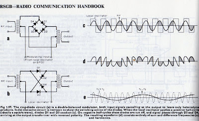
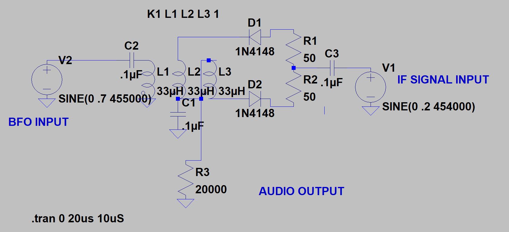
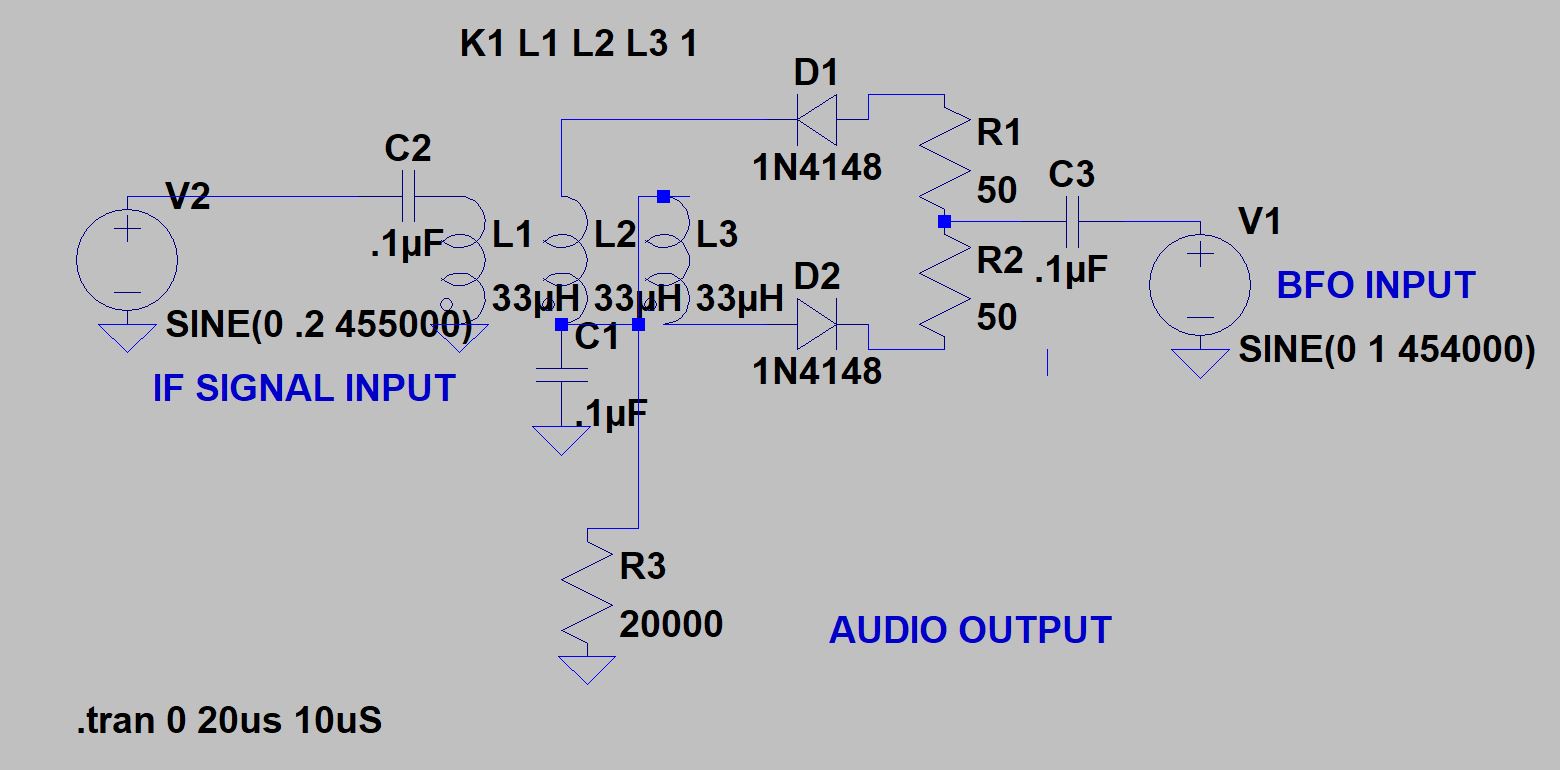
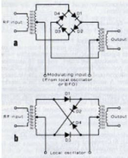
One suggestion: We should stop calling the diode ring a diode ring. I think “crossed diode mixer” or something like that is more descriptive. This circuit works not because the diodes are in a ring, but because two of them are “crossed.” From now on I intend to BUILD this circuit with this crossed parts placement — this makes it easier to see how the circuit works, how it manages to multiply by -1, and to avoid putting any of the diodes in backwards.
Diode Ring Magic
A Diode Ring Product Detector for the HA-600A? Problems.
Pete advised me to try this a week or so ago, but it took me a while to follow through and try it out.
I got the two diode, one transformer product detector working well, but with it a new problem arose: 455 kHz energy from the BFO was leaking past the product detector back into the S-meter/AGC circuitry. This showed up in the form of a constant S-3 reading when I switched to SSB/CW. This was annoying.
I figured the problem was that the only signal really being balanced out was the IF signal going into L1 of the product detector. I took another shot at putting the BFO signal into this port, with the IF signal going into the unbalanced potentiometer port. This did indeed take care of the BFO leakage S-meter problem, but once again the SSB did not sound great — I think the old problem of simultaneous envelope and product detection returned.
This was obviously a port isolation problem. I remembered that the diode ring “doubly balanced” configuration has much better port isolation. So on Sunday morning I built one, first in LTSpice and then on the bench.
For the bench model I used some PC board pads out of Pete Juliano’s $250,000 CNC machine. For the toroids I used two trifilar coils wound by Farhan’s dedicated staff in Hyderabad. The diodes were sent to me by Jim W8NSA. So there was lots of soul in this new machine.
The circuit worked in LT Spice and at worked well when tested on my bench with my FeelTech (for the BFO) and HP8640B (for the IF signal) sig gens with my Rigol ‘scope watching for the audio out.
But I ran into some problems when I popped the new board in there in place of the old product detector: The 455 kc BFO leakage problem is gone and the S-meter is where it should be, but…
— I’m seeing a return of the old simultaneous envelope and product detection problem. SSB was sounding scratchy again and indeed, when I removed the BFO signal from the diode ring circuit I could hear SSB signals making it into the audio amplifiers. These signals sounded just like AM signals as heard through an envelope detector without a BFO.
— The diode ring circuit also had a very bad effect on how the HA-600A worked in AM mode. It seemed like the new circuit was loading down the diode AM demodulator. SW broadcast signals sounded awful in the AM mode until I disconnected the IF input to the diode ring circuit (this input is NOT switched — it is always connected, even in the AM mode).
So, for now, am back to using the two-diode, single transformer, singly balanced product detector with IF signal going to the balanced (L1) port and the BFO going in through the wiper of the 100 ohm pot.
Any suggestions on how to overcome the problems with the diode ring circuit?


