The Ladybird TRF (Regen!) Receiver

http://www.mds975.co.uk/Content/trfradios02.html

My feelings about regenerative receivers and their possible connections to the nether-world are well known. But the receiver described on this beautiful British web site is almost enough to make me change my mind. Thanks to Stephen, G7VFY, for alerting me to this (and to so many other great sites!) I also find myself forced to give regens another chance because George Dobbs, G3RJV, was the original source of this design. It comes from a book he wrote in 1972. I love the wooden bread-board construction. Thanks Stephen! Thanks George!

Our book: “SolderSmoke — Global Adventures in Wireless Electronics” http://soldersmoke.com/book.htm Our coffee mugs, T-Shirts, bumper stickers: http://www.cafepress.com/SolderSmoke Our Book Store: http://astore.amazon.com/contracross-20

Stopping the AF oscillations in the Herring Aid 5

Thanks to all who responded. This morning I got a significant clue: Following up on Tony Fishpool’s suggestion, I separated the power supplies: I ran the RF amp, oscillator and mixer base bias off a small 12 V battery, with the mixer collector circuit and the AF amps running of the bench 12V supply. The AF oscillations completely stop under these conditions. So the feedback is probably taking place via the 12 V supply lines. 73

Our book: “SolderSmoke — Global Adventures in Wireless Electronics” http://soldersmoke.com/book.htm Our coffee mugs, T-Shirts, bumper stickers: http://www.cafepress.com/SolderSmoke Our Book Store: http://astore.amazon.com/contracross-20

Direct Conversion Receivers, AF Transformers, and Motorboating

The Herring Aid 5 is a direct conversion receiver (scroll down for details). It is a minimalist design from 1976 using parts available at Radio Shack stores. One of the parts no longer carried by Radio Shack is a 10K-2K ohm audio transformer. Following NORCAL’s 1998 design update I ordered an equivalent Mouser part (Xicon 42TU002-RC). I had been running the receiver with simple RC coupling instead of the transformer.

Yesterday the Mouser part arrived and I put it into the circuit. An increase in AF gain was immediately apparent, but the thing went into AF oscillation as soon as I turned up the AF gain.

I tried beefing up the AF decoupling. But I think the real problem is just the presence in the middle of the board of a rather large (1 inch x 1 inch) audio transformer. I moved it around a bit to get it away from the toroid of the preceding stage. This helped a bit, but it still breaks into oscillation if I turn up the AF gain.

Any suggestions? Or is this just part of the minimalist 1976 lifestyle?

Our book: “SolderSmoke — Global Adventures in Wireless Electronics” http://soldersmoke.com/book.htm Our coffee mugs, T-Shirts, bumper stickers: http://www.cafepress.com/SolderSmoke Our Book Store: http://astore.amazon.com/contracross-20

I Too Built a Tuna Tin 2

I didn’t plan on doing this. I didn’t even really want to do this. I’ve become a phone guy — I’m not into CW anymore. I figured I’d just finish the Herring Aid 5 receiver and settle the score from 1976 and that would be it. But everything I read about the Herring Aid 5 included references to the iconic Tuna Tin 2. Obviously I was also under the strong influence of my late February encounter with the original TT2 at the Vienna Wireless Winterfest. That Mojo is powerful stuff! Then my wife brought home this can of Russian tuna. The dimensions were perfect. Then I looked in my junkbox and found 40 meter CW crystals. That was it. I had to do it.

I built mine Manhattan style, using several of W1REX’s fantastic Me-pads. I also used as the final a transistor that Rex gave me at Winterfest. Thanks Rex. Soul in the New Machine.

I’m getting about 200 mW out. I;m on 7030 kHz and 7040 kHz and 7110 kHz. I have the TT2 up with my Drake 2-B (Herring Aid 5 integration will come later). I can feel the Mojo.

I just had my first contact with the TT2: I called CQ on 7110 and AB2RA came back. Jan was running 20 watts from an old 807 rig, listening with an old Hammarlund. So it was HB transmitter and vintage receivers on both ends! FB!

Our book: “SolderSmoke — Global Adventures in Wireless Electronics” http://soldersmoke.com/book.htm Our coffee mugs, T-Shirts, bumper stickers: http://www.cafepress.com/SolderSmoke Our Book Store: http://astore.amazon.com/contracross-20

Some notes on the Herring Aid 5


Sure, this receiver is not “state of the art.” But that’s the whole point. I wanted to finish the receiver project that I couldn’t finish back in 1976.

I tried to stick as close as possible to the original design and parts. NORCAL came up with an updated schematic in 1998 with parts that are more readily available. But Designer Jay Rusgrove was shooting for something that could be built with all the parts coming from Radio Shack. I think that is probably one of the factors that attracted me to the project way back when. That’s why Jay went with varactor tuning (no hard-to-get variable caps!). And that’s why he used coils that were wound on Radio Shack 10uH RF chokes (no need for hard-to-find toroidal cores). In this sense there is some common ground between the BITX rigs and the Herring Aid 5.

I stuck with the RF-choke as a coil idea for the VFO, but went with the NORCAL-prescribed toroids for the front end and mixer coils. (I may go back and try to use chokes in these circuits, but I’m not sure my junk-box will yield the kind of RF chokes that Jay used).

I wish I had known a few things when I was building this back in 1976: More knowledge about how to wind the coils would have been a big help. I wish I had realized that I could use a SW receiver to get the oscillator on the right frequency. I guess this was in the days before Ugly and Manhattan building techniques, but it would have been nice to know that there was no need to actually etch a board for this project (I did!).

The coils really are a bit tricky. Jay didn’t use any trimmer caps, so I guess you had to just hope that the front end coil and cap resonated somewhere near 40 meters. As for tuning the oscillator, Jay recommended scrunching and un-scrunching the turns on the RF choke. Yikes! Give me some trimmer caps!

I also found that you have to watch the level of the RF going from the oscillator to the mixer. Too much, and the receiver is deaf. Too little, same result. You need to experiment a bit with the number of turns on the pick-up coil from the oscillator.

The warnings about the pitfalls of that single BJT mixer were right on the mark: Lots of AM SW breakthrough. But I kind of like the background music. Strong RFI from local FM broadcast stations was another story (WMZQ is a country music station!). I reached into my junkbox and found a low-pass filter from a Heathkit DX-60. I just put that between the antenna and the receiver and the country music was GONE!

I really love this little receiver. I have it playing 40 meter CW as I type. It sounds great. I feel the urge to built a Tuna Tin 2 and put both of them on 40.

In the original Tuna Tin 2 article, Doug DeMaw notes that Jay Rusgrove was thinking of doing a companion receiver and says that he was thinking of calling it the “Clam Can 5” ! There were jokes about receivers for hams with “tin ears” and about there being “something fishy” about these rigs.

Thanks to Doug DeMaw and Jay Rusgrove and QST for bringing us these little circuits.

Our book: “SolderSmoke — Global Adventures in Wireless Electronics” http://soldersmoke.com/book.htm Our coffee mugs, T-Shirts, bumper stickers: http://www.cafepress.com/SolderSmoke Our Book Store: http://astore.amazon.com/contracross-20

Peter Parker’s Knobless Wonder Minimalist SSB Rig

Oh man, Peter Parker has done it again! As he did with the Beach 40, he has come up with a circuit that will attract a lot of attention. It is a single frequency SSB transceiver with no knobs (or windows, or menus!)

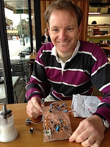
Peter Marks recently had breakfast in Melbourne with VK3YE:
http://blog.marxy.org/2013/05/melbourne-meetup-with-homebrew-legend.html
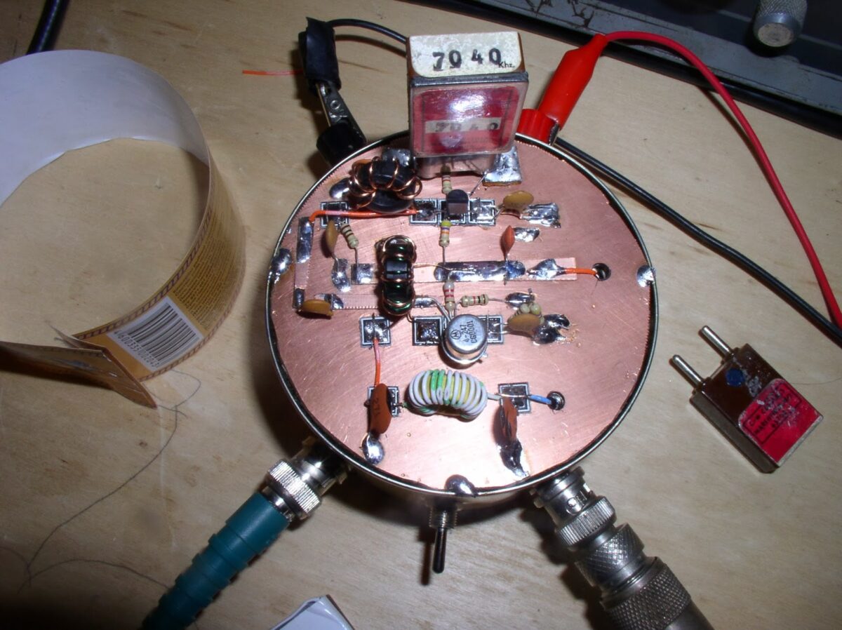
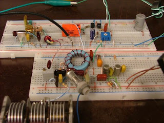
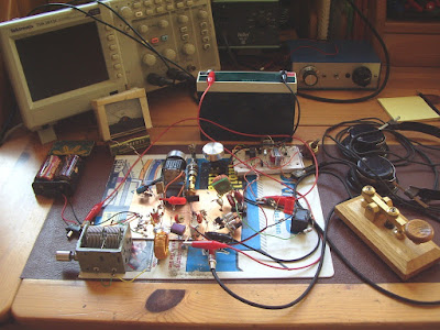
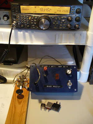
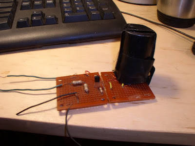
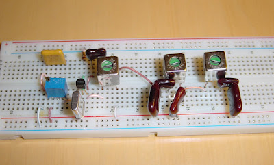
There are some great pictures of the new rig, and the Beach 40.

Here’s the message from VK3YE (to the Minimalist Radio Group) that may
someday be seen as the start of the Knobless Revolution:

Some might reckon that SSB is inevitably too complex to be in the minimalist
class, but I beg to disagree.

I reckon you could build a whole SSB transceiver in 2 days of solid work. I
took a day to build what will be described below up to the stage where it

was receiving & producing a low level SSB on Tx.

Take this recipe:

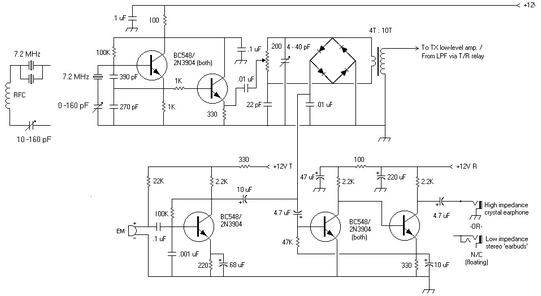
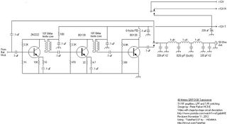
1. Build the back end of the BitX http://www.phonestack.com/farhan/bitx.html
That is everything to the right of (and including) the Q2 & Q12 stages.

2. Use cheaply available 7.159 MHz crystals in the crystal filter and
carrier oscillator. Keep filter capacitor values the same. Remove L3 in the
carrier oscillator circuit. Use a slightly bigger trimmer in the carrier
oscillator (say up to 50 pF) and wire in series with crystal. Align trimmer
so carrier freq is 7160 kHz.

3. Build a power amplifier stage / relay / LPF as per the Beach 40. Just
the last 2 stages (using BD139s) should be enough. Output maybe 2w.

The result is a 10 transistor / 1 IC SSB transceiver on 7160 kHz. It’s
crystal controlled but at least during the day 2 watts to a good antenna
should be enough for people to hear and reply to your CQ calls up to 800 –
1000 km away. Of course you could go a bit more minimalist and remove the
LM386, substituting 1 transistor instead (as per the original Beach 40)
which is what I did.

The main thing that’s odd is it has no knobs – no tuning, RIT, volume, RF
gain etc. Just sockets – for mic, phones, antenna and power to feed it what
it needs (Rx RF, Tx audio, DC power) and give what you want (Rx audio and Tx
RF).

It is philosophically different to using any other transceiver. You either
accept what the radio dishes up (frequency, AF gain, mic gain etc) or you
don’t. On or off – there is no other state. Take it or leave it. Like a
cat this is a radio that lives on its own terms.

Those used to fiddling with adjustments will find the ‘knobless wonder’
transceiver causes them to be at a loose end. Those so afflicted will smoke
more, bite their nails more or eat junk food more. Sometimes elegant
simplicity in radio can be a health hazard – maybe knobless rigs should
carry health warnings.

On the other hand, and in my view this outweighs the above, there is the
aesthetic satisfaction that comes from using a rig that cannot be made any
simpler. Especially if it’s a mode, like SSB, that’s widely thought
constructionally complex. Plus it takes little in return – the power
consumption will be a fraction of what a commercial rig will demand.

73, Peter VK3YE
Our book: “SolderSmoke — Global Adventures in Wireless Electronics” http://soldersmoke.com/book.htm Our coffee mugs, T-Shirts, bumper stickers: http://www.cafepress.com/SolderSmoke Our Book Store: http://astore.amazon.com/contracross-20

AA1TJ Crosses the Pond using an Electric Razor!

Take a look at Michael’s Razor Rig, made from parts salvaged from his electric razor. I was thinking that perhaps on the receive side a fox-hole receiver made with a rusty Gillette blade would fit in nicely with the shaving theme. Very glad to see the AA1TJ blog getting more active.

http://aa1tj.blogspot.com/2013/04/talking-to-france-via-my-electric-razor.html

Our book: “SolderSmoke — Global Adventures in Wireless Electronics” http://soldersmoke.com/book.htm Our coffee mugs, T-Shirts, bumper stickers: http://www.cafepress.com/SolderSmoke Our Book Store: http://astore.amazon.com/contracross-20

AA1TJ’s Latest QRPp Rig

From Mike, AA1TJ:

I called CQ on 20m CW for a couple of hours yesterday afternoon with no response. With the cadence of my own Morse tugging at my eyelids, I was suddenly shaken awake by a brisk signal returning my call and signing CU2BV. I snapped out a 579 report and turned it over. The dits and dahs in my headphones told me it was Fernando; operating from São Miguel island in the Azores. He reported a weak but solid copy (529) of my fifty milliwatt signal.

Here’s the radio that I used yesterday. The one-transistor transmitter is to the left of the red relay on the top board. The single transistor is a germanium surface-barrier device made by Philco in August of 1958. To the right of the relay is a two-transistor time-delay circuit used to switch the antenna between the transmitter and the receiver. My receiver on the lower proto-board is a reproduction of my first shortwave receiver: a $7 Japanese kit that I bought at Radio Shack when I was 13 years-old.

Fifty milliwatts is some twenty-four times less power than was used by an old double D-cell flashlight. I later learned that my signal was nearly simultaneously picked up by an automated receiver located just west of Dusseldorf, Germany.

Snowy Vermont to the lush Azores – some 1500miles off the coast of Portugal – with less power than is consumed by a beeswax candle…is it any wonder that I love radio? 😉

Our book: “SolderSmoke — Global Adventures in Wireless Electronics” http://soldersmoke.com/book.htm Our coffee mugs, T-Shirts, bumper stickers: http://www.cafepress.com/SolderSmoke Our Book Store: http://astore.amazon.com/contracross-20

Vanguard!

Wow, Vanguard even looks like a QRPp satellite.

I suspected that something was up: I noticed that Mike Rainey, AA1TJ has recently been crossing pond with a QRPp Germanium rig… Then Steve “Snort Rosin” Smith clued me in: The next period of Vanguard QRPp Activity Days begins tomorrow. “Club 72” has a nice write up, and a nice collection of pictures of the Vanguard rigs that have been built around the world:

http://www.club72.su/vanguard.html

Go Germanium! Go Vanguard!

Our book: “SolderSmoke — Global Adventures in Wireless Electronics” http://soldersmoke.com/book.htm Our coffee mugs, T-Shirts, bumper stickers: http://www.cafepress.com/SolderSmoke Our Book Store: http://astore.amazon.com/contracross-20

Schematic of the VK3YE “DSB-On-The-Beach” Rig

Peter Parker’s amazing 8 transistor DSB rig (featured in an equally amazing YouTube video — see earlier blog post) has sparked a worldwide resurgence of QRP minimalism. There is now a lot more activity on the “Minimalist QRP Transceivers” Yahoo group (be there or be square). Steve “Snort Rosin” Smith WB6TNL is minimalist mentoring to the max — with his help it looks like more VK3YE transceivers will soon be on the air. Steve was kind enough to take the info from Peter’s video and turn it into a .pdf schematic (see above). It is in the file section at the Minimalist QRP Transceivers group. I was, of course, pleased to see the inclusion of a robust 7 element low pass filter.

Michigan Mighty Mites are also tickling the ether. I may pull out my single MPF-102 Yingling 80 meter rig. You can join the Minimalist group here: http://groups.yahoo.com/group/Minimalist_QRP_Transceivers/

Our book: “SolderSmoke — Global Adventures in Wireless Electronics” http://soldersmoke.com/book.htm Our coffee mugs, T-Shirts, bumper stickers: http://www.cafepress.com/SolderSmoke Our Book Store: http://astore.amazon.com/contracross-20

The Parasaki: DL3PB’s Amazing All Diode Transceiver

JBOD! FB!

Hi folks,
I’d like to share with you a long-cherished dream, that recently came true, forty years after I came to read about hams using tunnel diodes to make QSOs when I was aged twelve or so:

Finally I managed a first skywave QSO with my PARASAKI-transceiver, an ‘all diode’ rig: Christophe/F8DZY replied to my very first call on 20m band in REF-contest last weekend. I was running 2mW into a temporary vertical dipole on my balcony. Distance between us is 918km – obviously OM Christophe has excellent ears.

Those interested in the cruel details of my circuit, please find attached a schematic and a photo of the pretty ugly setup. The circuit is designed straight-forward with exception of the parametric VXO, derived from Mike/AA1TJ’s famous Paraceiver design. (see http://fhs-consulting.com/aa1tj/paraceiver.html )


The low impedance of the high peak-current tunnel diodes make it very difficult to built a really crystal controlled oscillator rather than an LC-oscillator, synchronized by the crystal more or less, at least on the higher SW-bands. The Parametric VXO provides a crystal-stable, chirp-free signal on expense of an output power of two milliwatts only instead of ten, but with an amazing spectral purity, no need for a low pass filter or such. Of course it sounds pretty cool making a QSO with a ‘bunch of diodes’ and a parametrically excited crystal, but believe me or not, I’d preferred to bring that full ten milliwatt into the air – on the other hand that approach allowed to tune the rig a bit ( ~ 5kHz/per xtal), which turned out to be much more valuable than a few milliwatts more while being ‘rock-bound’.

The receiver in its ‘gain-less’ version works fine for strong signals – while listening to QRP(p) stations, the moderate gain of the audio amplifier helps a lot. A comfortable frequency shift between receive and transmit is realized by the 5µH inductor at the LO-port of the mixer, with little effect on sensitivity.


Thanks for the bandwidth, OMs, won’t bother again you with such mails, unless I make a cross-pond QSO with that rig ( not that likely ) or any skywave QSO with homemade semiconductors ( probably impossible )…

72!

Peter/DL3PB


Our book: “SolderSmoke — Global Adventures in Wireless Electronics”http://soldersmoke.com/book.htmOur coffee mugs, T-Shirts, bumper stickers: http://www.cafepress.com/SolderSmokeOur Book Store: http://astore.amazon.com/contracross-20

Bike Radio II

Thanks for all the suggestions on the bike radio. I googled around a bit and found a schematic that seems very similar to the little receiver I’m working with. I almost certainly would be better off starting anew (perhaps keeping the AF circuitry). But it is interesting to see how a simple AM receiver works. That first transistor is an autodyne circuit — both a mixer and a oscillator.

Our book: “SolderSmoke — Global Adventures in Wireless Electronics”http://soldersmoke.com/book.htmOur coffee mugs, T-Shirts, bumper stickers: http://www.cafepress.com/SolderSmokeOur Book Store: http://astore.amazon.com/contracross-20

Steve “Snort Rosin” Smith: Silver-Tongued Devil! Dual-band “Vlad the Inhaler” RX

You’ll see in the comments attached to my last blog post that our man on the left coast, Steve Smith, gave that cute little Doug DeMaw/Vlad Polyakov receiver a name that might set American-Russian ham relations back a bit: He called it “Vlad The Inhaler.” Good one Steve! (But you might want to stay out of the diplo game!)

It occurred to me that with the installation of one little switch in the diode part of the circuit, we could turn this into a dual-band RX. Take a look here:

http://soldersmoke.blogspot.com/2010/03/polyakov-plus-dual-band-receiver-with.html

Check out “SolderSmoke — Global Adventures in Wireless Electronics”
http://soldersmoke.com/book.htm

Homebrew Two Dollar Oscilloscope

This is from a short article in the April 1997 issue of Electric Radio magazine. The author is Bob Dennison, W2HBE. Bob is a real genius, and the author of many inspirational articles in ER.

The Sundt Engineering Company of Chicago was advertising this kind of device in the June 1936 issue of Short Wave Craft Magazine. Only two dollars (but that was big money in 1936). From Bob’s article: “When the transmitter is modulated with a single audio tone, the waveform of the modulated carrier will be seen. By varying the motor speed (horizontal scan rate) the pattern can be synchronized or made to stand still. Percentage modulation is readily estimated by simple inspection of the display.”

So here we have the perfect minimalist ‘scope to go with a minimalist AM transmitter!

Snort Rosin’s Mighty Mite: The Super Duper X Spy Transmitter

Hi Bill,

Attached is a picture of the remains of my transmitter, “The Super Duper X Spy Transmitter“. My little rig didn’t sit around; it made QSOs the day it was finished, 41 years ago. Since then it has bounced around in various junk boxes and had some parts robbed for other projects but thankfully it’s still mostly intact.

I constructed it based upon the original article in Ed Noll’s book, “Solid State QRP Projects”, pg. 51, Project 17, “10 160 All-Band Two Watter”. That transmitter was later to become known as the Michigan Mighty Mite.

My MMM (or SDXST if you will), features a built-in relative power detector, a microswitch key (upper right-hand corner), room for an internal 9 Volt battery and a jack for external power. The jacks are each different; a BNC for the antenna, a 3.5 mm closed-circuit jack for the key, a 2.5 mm for the relative output meter and a phono jack for the external power. My notes say that I added a .1 uF Emitter bypass and that it increased the power output by 50%. I also used a toroid for the output tank instead of the 1-3/4″ coil form called for in the article. Use of the “Sucrets” box was not my idea; I got it from one of the ham mag’s. of the day, probably 73.

Your coverage of those little rigs has motivated me to restore mine and make some QSOs for old times sake. With, of course, the proper output filter :-). I’ll send a picture of the ‘guts’ when it’s finished.

73…….Steve Smith WB6TNL
——————————-
Thanks Steve. Great stuff. But… WHERE’S THE OUTPUT FILTER?

Another Mighty Mite Success Story!

Bill:

I started listening to Solder Smoke this winter, and I’m now up to episode 81. Since I’m new to homebrewing, I wanted to say that I enjoy the discussion of good projects to start on for homebrewing equipment, particularly the discussion of the Michigan Mighty Mite, which I understand was your first HB TX project. After hearing you mention the transmitter on the show, I looked it up on the Internet and found the schematic. A few hours later and I was on the air. My first contact with it was with KB1TSG, Jim in Randolph VT, receiving a signal report of 449. From my QTH in Monroe, ME that’s a distance of 186.5 mi ( 300 km) as the crow flies.
I’ve learned a lot listening to Solder Smoke over the past two months and listen to it while in the car, at work, and while walking my dog on the back roads of Maine. Thanks for such a great educational and entertaining show.

73,
Neil


Neil Caudill
KB1UAL

20 years after construction… Mighty Mite Makes Contact!

Bert, WF7I, sent us this report from the nuclear reactor building at UVA. You can almost feel the excitment! Congrats Bert!

Bill:

I’m ecstatic to report that my MMM made its first QSO, after almost 20 years, last night at the University of Virginia ham club at the nuclear reactor! I worked W4OEQ, Tom in McMinnville, TN. He gave me a 459 report. I was running about 300-500 mW (hard to tell with our meter) out of the MMM into our inverted vee up high in the trees of Observatory Hill at UVa. I also have three witnesses to the event: our club president, Mark KJ4IEA; club Treasurer Will, KI4LGE; and member Alex, KJ4YWP. I received a round of applause from our group after the QSO was complete!

It was a very satisfying moment to be sure. Not only to make a QSO with this rig from my past and all those memories, but to do it at the re-vitalized UVa ham club, which has its own long, off-and-on history dating back to the 1930s (at least), and to do it with a captive audience! Our club members, mostly younger guys 18-22 years old, have never done CW and always are in a mesmerized/stunned condition when they see me tapping out the dots and dashes, and copying it in my head! Everyone was very silent and focused during the QSO.

72/73!

Bert WF7I

The Return of the Michigan Mighty Mite

Michigan Mighty Mite — N2CQR/HI8 version

Bert, WF7I, (our correspondent at UVA Charlottesville), wrote yesterday about his past and recent adventured with a little rig that got a lot of us started in the scratch-built homebrew game: The Michigan Mighty Mite. I built one in the Dominican Republic, probably in 1993. I never worked anyone with it, but was really pleased to get the thing oscillating. I still have remnants of it (sans crystal) — see above. Bert’s e-mail and AA1TJ’s recent derring-do make me want to dust off that little single FET transceiver for 3.579 MHz that I built in Italy. One QSO would make me happy. At least this minimalist stuff is keeping me away from the regens…

Here’s a good article on how to build one:
http://www.qsl.net/wb5ude/kc6wdk/transmitter.html

Here’s a site from Dave, WA5DJJ, who built a bunch of these rigs:
http://www.zianet.com/dhassall/Michmitymite.html

Bert’s e-mail:

Hey Bill.

The AA1TJ postings on your blog motivated me to unearth my old Michigan Mighty Mite (the “MMM”). For me there’s a lot of history, even emotion, there. I built this little rig with my friend AC7CA when we were both finishing up high school. Neither of us knew what was really going on in this circuit, other than some vague thoughts about resonance and that a transistor amplifies.

What was important to us at the time was more the fit-and-finish of the box that it was in, and making QSOs, rather than working out the theory behind the schematic. I’ll email you a photo of the box as it stands now. We got a nice, blue plastic project box from Radio Shack, and figured out that those small iPod (used to be called “Walkman”)-style headphone sockets made great crystal sockets as well (they really do). I remember vividly the two of us planning out the radio, I remember trying to work with plastic (not so easy, it tended to melt and scuff up), and attaching the air-variable capacitor (not a small feat with the limited tools available). But the end product looked like a much more impressive rig than it really was. This oversized blue box with a big tuning knob, bright colored red and black banana power terminals, the cool little crystal sticking out of the top, and the Dymo-label tape proclaiming, “Rig Master” (or “blaster”, or something similar — I have to actually go see what it said!). 1/2 W of power came out of this very simple oscillator, just as advertised. But to this day, I don’t know if either of us ever even made a QSO with the thing! The thrill was in the assembly of a rig from a schematic in CQ magazine, the fellowship of the two of us working on it, and seeing the thing actually WORK as promised. Time moved on, and it ended up getting shoved to a back corner of my room, and when college and work came along, it almost got totally forgotten and collected dust.

Anyway, the blog postings made me think of low-powered QRP, and I dug it out again, dusted it off, and pulled out some crystals. The thing still works just as it did 20 years ago! I was very happy to see that. I guess one of the advantages to ultra-simple, low part count rigs is that not much CAN go wrong! And if it does, it only costs a few pennies, or nothing, to fix.

The rig went on the air on Saturday night, and it was quite an interesting contrast on the work bench. On one side, my Kenwood TS-2000, a state-of-the-art (or nearly so) DSP rig, with the “glowing numerals” and a computer interface. Next to it, the MMM, straight key and a pile of rocks! A single “super antenna” compact vertical was erected on a tripod in my backyard, with a coax coming in to the shack to a switch (functioning as a “T/R” switch, in a way). In one position, my gazillion-transistor appliance rig would function as a ridiculously sensitive and over-the-top receiver for the task at hand. In the other position, my homemade single-transistor MMM would transmit out to the vertical.

I called CQ till my hand/wrist was sore, and QSY’d between the 4 freqs I had to choose from, but to no avail. I am not deterred however. This evening, following the W4UVA club meeting, I will hook it up to our 40 m inverted vee high in the woods overlooking the nuclear reactor. It would be fitting if the possible first ever MMM QSO came from this setup.

Late Sunday night, after I had exhausted myself from “pounding brass”, I was reading more from “Solder Smoke — The Book”, and found one picture that really made my day. Sitting in front of your Tandy and just to your left, was a small blurry object. Reading the caption, I saw that it was YOUR Michigan Mighty Mite! What a fitting way to end a wonderful weekend of hamming.

72/73,
Bert WF7I

Muntzing with Michael


Snappy title, don’t you think? I think it could become a TV series, maybe if the Discovery channel someday gets into QRP and homebrew. In his QRP-L message about his latest rig, Michael, AA1TJ, said that he had “spent the morning ‘Muntzing’ G3XBM’s, fine little XBM80-2
transceiver for the MAS (Minimal Arts Session) event.” For those of you who don’t recognize the verb “to Muntz”, Michael is referring to one of the early manufacturers of TV sets, who, in an effort to reduce costs, ruthlessly went through his engineers’ designs, throwing out every component that wasn’t absolutely necessary. So I think Michael — who I often refer to as the “Poet Laureate of QRP” — has given us a new and very useful verb: To Muntz! (This comes in a month in which another very useful word was given to us: G3RJV’s “socketry.”)

Michael said, “I felt like the guy in the movies yesterday; throwing everything overboard that’s not absolutely necessary in order to keep the Zeppelin/balloon aloft long enough to make landfall. :o)” The results speak for themselves. The schematic above and the picture below show Michael’s entire transceiver. And he made a bunch of contacts with it.

One word of caution: Minimalist radio is not for the faint of heart. As the parts counts go down, the degree of difficulty for successful contacts goes up.

Check out Michael’s page: http://www.aa1tj.com/Menos es MAS.html

Here’s a picture of the rig:

Homebrew transistors, QRSS Blog, Shep Show, Nose as toubleshooting tool

Some odds and ends today:

Ed, KC2TYP alerted me to this one: Jeff, K7JPD, has a very intriguing blog post about homebrew transistors. I suspect AA1TJ will have a rig made of these things on the air within a week. Check it out:
http://jeff-duntemann.livejournal.com/227856.html

There is a new blog for the Knights of the QRSS:
http://knightsqrss.blogspot.com/

Dave in Ireland sent me a link to the Jean Shepherd show in which he discusses his first soldering iron: http://www.archive.org/download/JeanShepherd1975/1975_07_30_Soldering_Iron_full_show.mp3

Alan, WA9IRS, alerted us to a nice EDN article on using your nose as a trouble-shooting tool:
http://www.edn.com/article/CA6713738.html