As young James Clerk Maxwell used to say, “What’s the go of it?” and “What’s the particular go of it?”
I studied this circuit carefully when I was using it as a balanced modulator in my DSB rigs. I wrote up my conclusions in my book “SolderSmoke — Global Adventures in Wireless Electronics.”
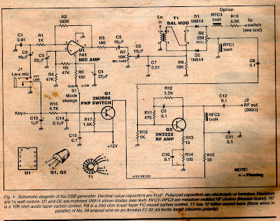
BALANCED MODULATOR CONFIGURATION:
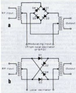
When I was using it as a balanced modulator, I had the RF “carrier” signal going into L1. This RF signal was 7 dbm, enough to switch the diodes on at voltage peaks. With the “center tap” of L2/L3 grounded for RF, this meant that when the “top” of L2 is negative, the “bottom” of L3 is positive. In this situation BOTH D1 and D2 will turn on and conduct.
When the top of L2 is positive, the bottom of L3 is negative and neither of the diodes is on. Neither conducts.
So we have the RF signal turning the diodes on and off at the frequency of the RF signal.
Audio from the microphone and mic amplifier is sent into the center tap connecting L2 and L3. The level of this audio is kept low, below the point where is could turn on the diodes. The center tap IS grounded for RF by the .1uF capacitor, but it is NOT grounded for AF. That is key to understanding this circuit.
In essence by turning the two diodes on and off at the rate of the RF signal, the audio signal is facing severe non-linearity through the diodes. We could say it is alternately being multiplied by 1 and 0. This non-linearity is what is required for mixing. We therefor get sum and difference products: Sidebands. At this point, Double Sideband.
The way the transformer is set up means the RF carrier signal is balanced out: Even when the two diodes conduct, the top of R1 and the bottom of R2 are of equal and opposite polarity, so there is no carrier signal at the junction of R1 and R2 (they are actually a 100 ohm variable resistor that can be adjusted to make SURE they balance out). So the carrier is suppressed and all that remains are the sidebands: Suppressed Carrier Double Sideband.
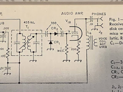
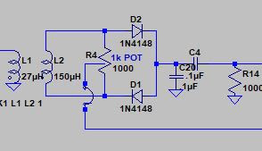
PRODUCT DETECTOR CONFIGURATION:
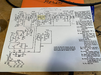
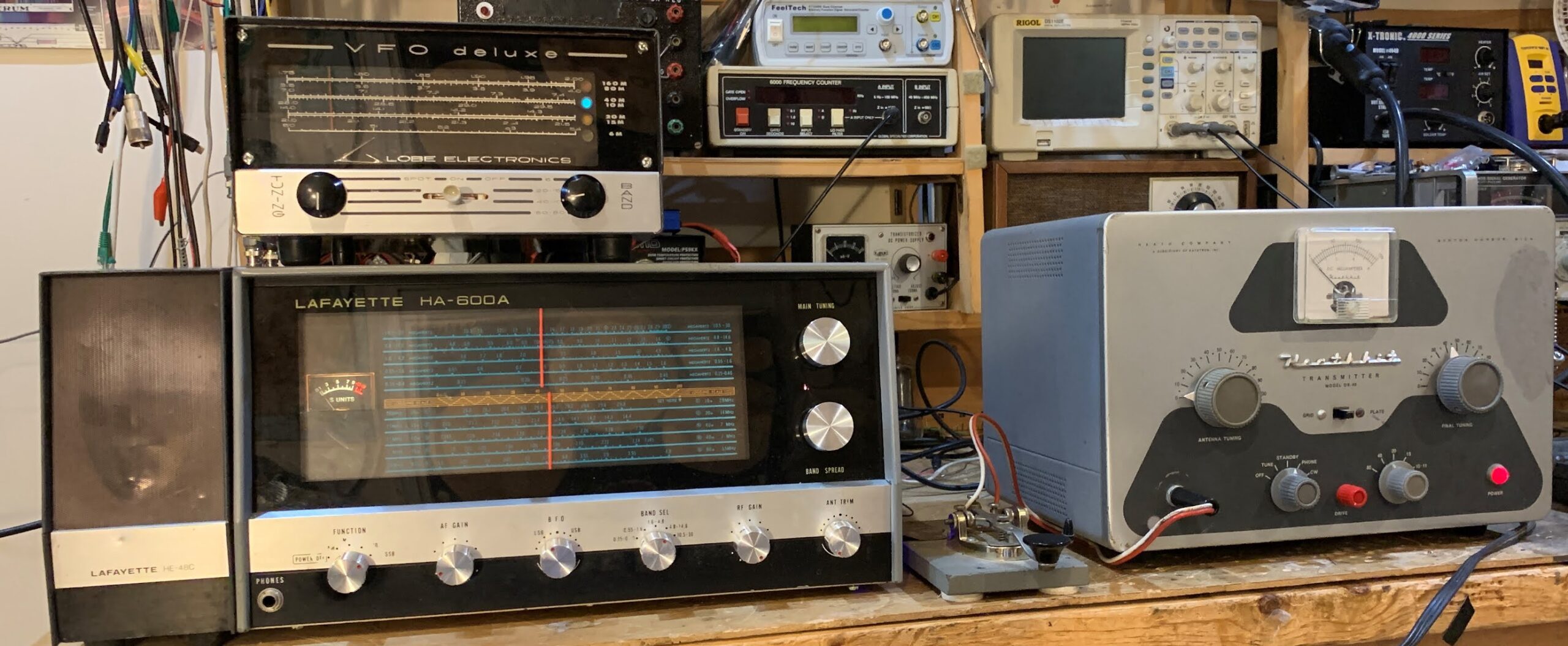
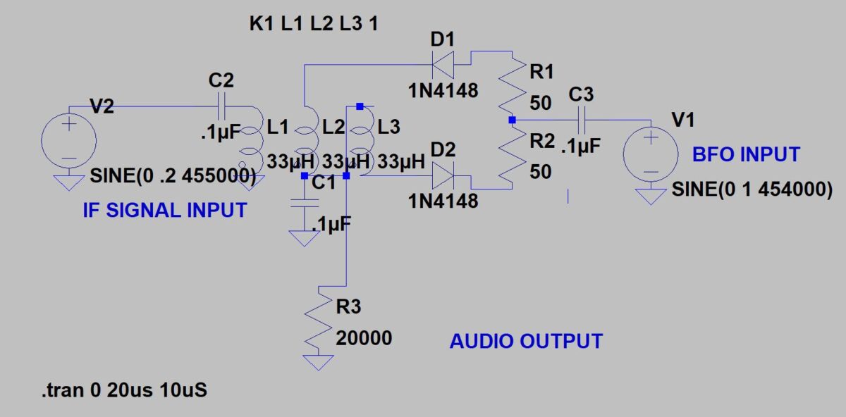
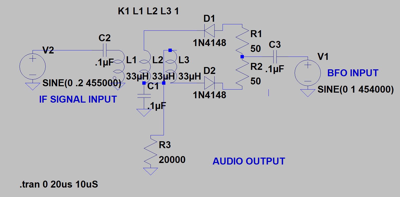
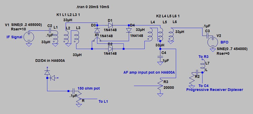
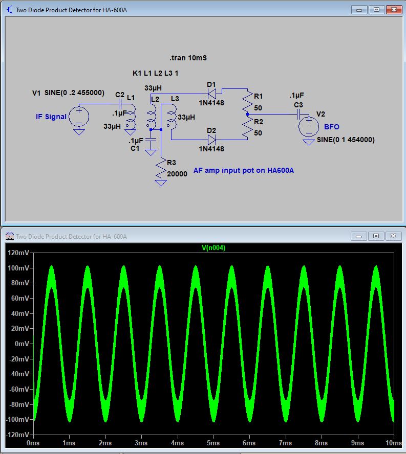
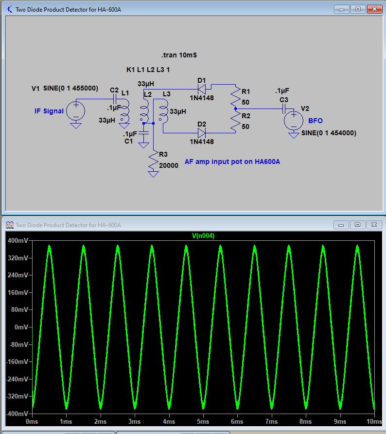
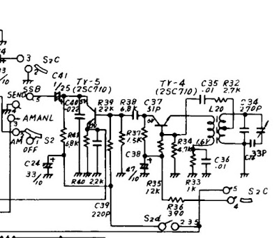
What happens when we use this circuit as a product detector in a receiver? Let’s assume we are working with a 455 kc IF. If you run a 454 kc 7 dbm BFO signal into L1, it will turn the diodes on and off as described above. But you will NOT be able to put the 455 kc IF signal into the center tap of L2/L3 — that center tap is GROUNDED for 455 kc. So you will have to run your IF signal into the resistors, and take the audio output from the center tap of L2/L3. This works. I tried it in my HA-600A. But there is a problem: Envelope detection.
In this arrangement, we are balancing out NOT the 455 kc IF signal, but instead we are balancing out the BFO. We don’t really NEED to balance out the BFO — it can easily be knocked down in the audio amplifiers, and IT is not responsible for the problematic envelope detection. We DO need to balance out the IF signal, because if that gets through we can get simultaneous “envelope detection” and product detection. And believe me, that does not sound good.
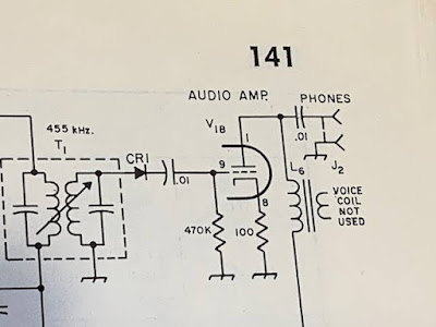
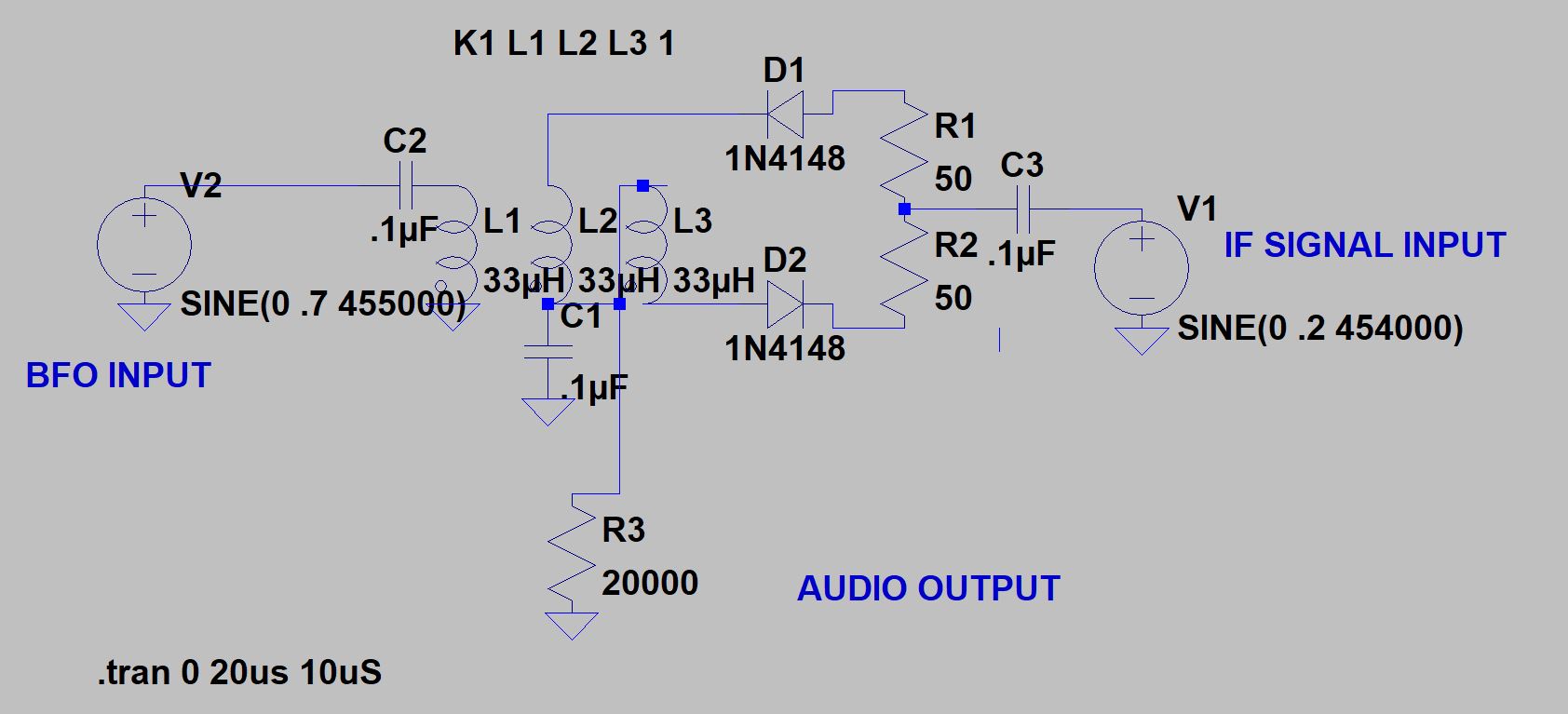
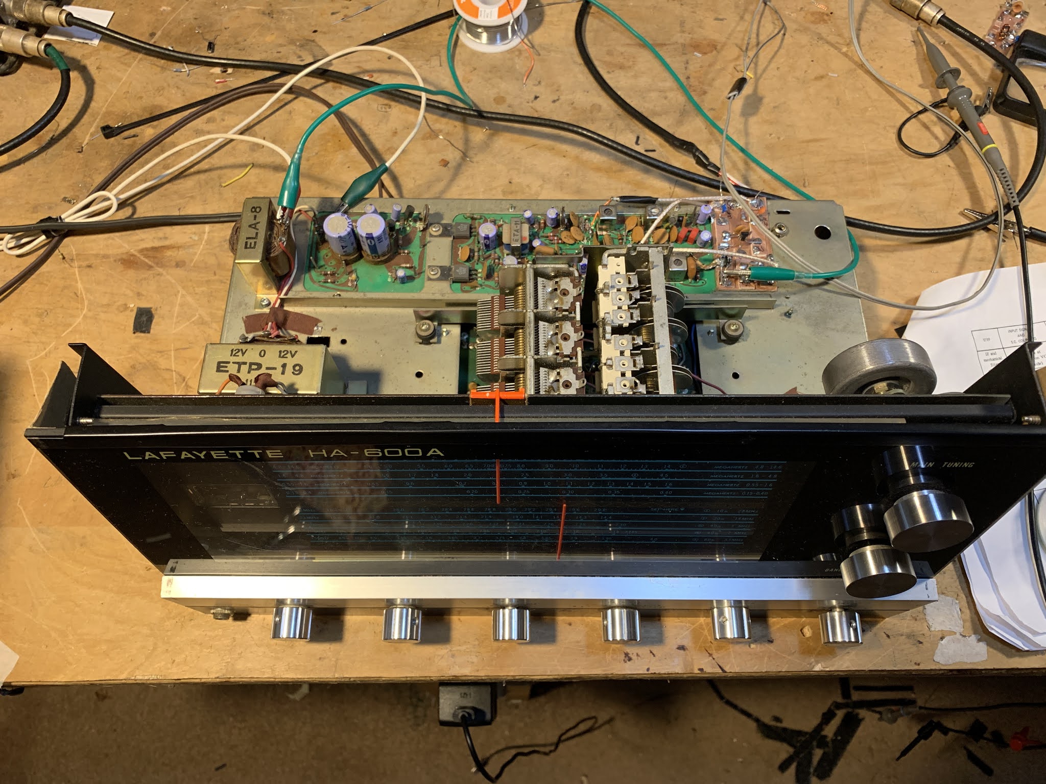
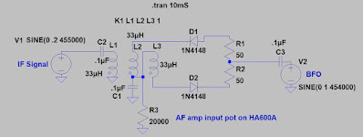
So I tried putting the IF signal into L1, and the BFO signal into the resistors (as shown above). I took the audio from the junction of L2/L3. This seemed work better, with envelope detection greatly reduced.
BUT WHAT’S THE GO OF IT?
But how is this circuit mixing in this configuration? The strong BFO signal is still controlling the diodes, BUT, with the BFO signal coming in through the resistors, when the top of R1 is positive the bottom of R2 is ALSO positive. In this situation D1 will conduct but D2 will not. The IF signal is facing a big non-linearity. This will result in sum and difference frequencies. The difference frequency will be audio. But with D1 and D2 turning on and off in a very different way than we saw in the balanced modulator, how does the mixing happen?
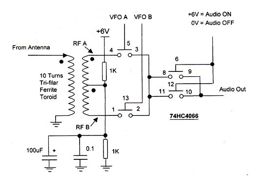
I think the answer comes from the summer 1999 issue of SPRAT, the amazing journal of the G-QRP club. Leon Williams, VK2DOB wrote an article entitled “CMOS Mixer Experiments.”
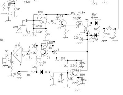
Here is Leon’s 74HC4066 circuit:
I think those two gates (3,4,5 and 1,2, 13) are the functional equivalent equivalent of the two diodes in our product detector. In Leon’s scheme the VFO is supplying signals of opposite polarity. Ours is providing only one signal, but the fact that the diodes are reversed means that they act just like the gates in Leon’s circuit. The transformer is almost identical to the one we use in the product detector.
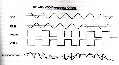
Let’s look at the output from Leon’s circuit:
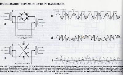
“VFO A” going high is the equivalent of the BFO going to its positive peak and D1 conducting.
“VFO B” going high is the equivalent of the BFO signal to its negative peak and D2 conducting.
Take a ruler, place it vertically across the waveforms and follow the progress at the output as the two signals (RF A and RF B) are alternately let through the gates (or the diodes). You can see the complex wave form that results. The dashed line marked Audio Output shows the difference frequency — the audio. That is what we sent to to the AF amplifiers.
One concern remains:
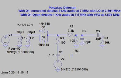
What happens when the 455 kc IF signal getting to L1 get so strong that IT also starts to turn the diodes on and off? I think this will result in distortion, and we can see this in LT Spice.
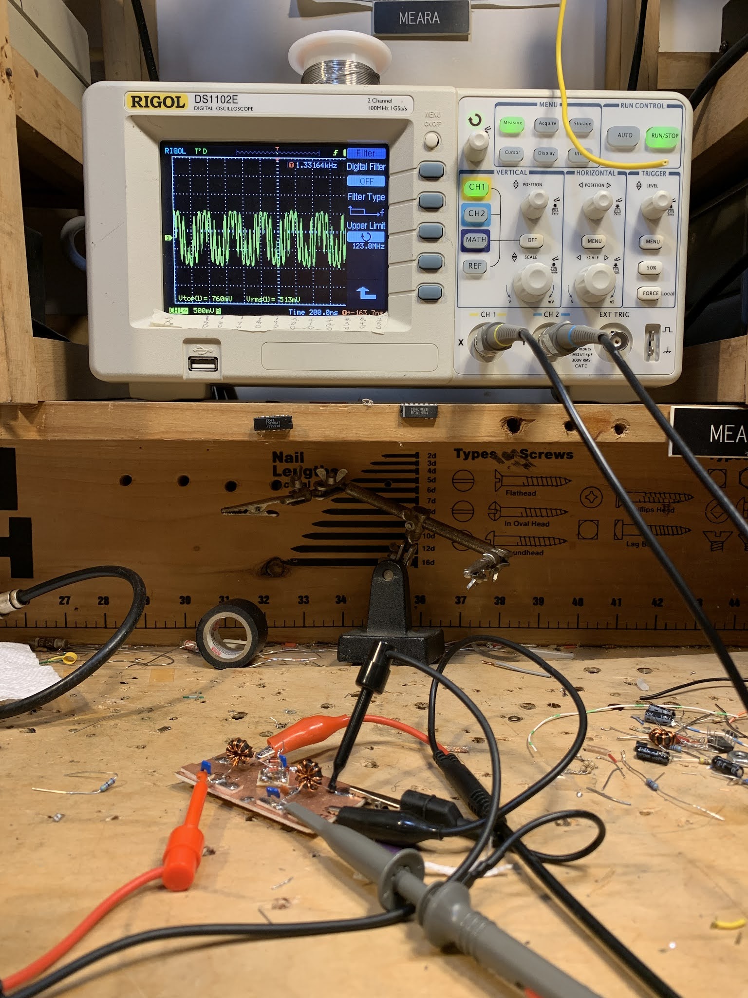
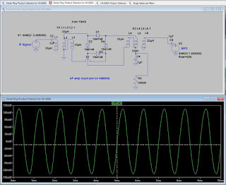
Here is the output waveform when the If signal at L1 is kept below the level that would turn on the diodes:
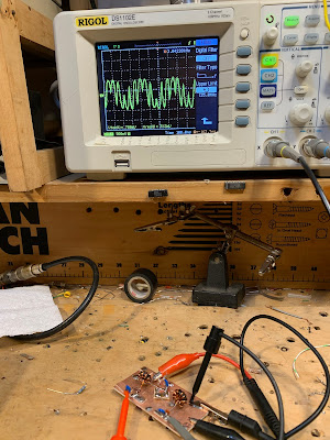
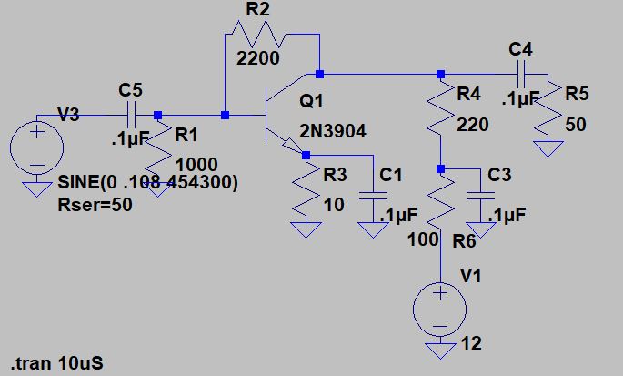
Here you can see it with a much stronger IF signal:
The output waveform becomes more of a sawtooth.
How can I prevent this from happening? I know AGC should help, but the AGC in this receiver doesn’t seem to sufficiently knock down very strong incoming signals.
Does my analysis of these circuits sound right?