
Thanks again to Farhan for visiting us. It was great to see his reaction to my humble implementations of his great designs. I got him to sign my BITX17. This was really a fantastic day for me and for my family.
Category: Juliano — Pete
DiFX! My New NE602 Rig is On the Air
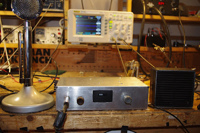
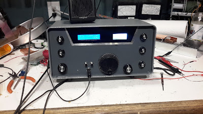
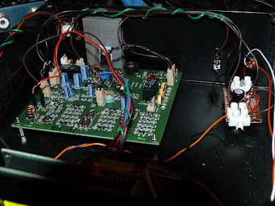
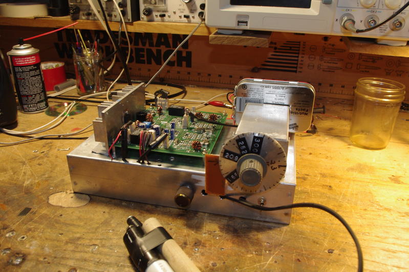
Pete would call this a DiFX: a transceiver that is Different from a BITX. This started with my effort to get an Si5351 working with a little 1 inch square OLED screen. Tom Hall AK2B helped me with the software (thanks Tom). Once I got that done, I figured I could build a simple receiver with a homebrew 11 MHz crystal filter, two NE602 chips, and an LM386 AF amplifier. That was working great, then Pete told me to turn it into a transceiver. I used some of Pete’s boards (thanks Pete).
The Epiphyte transceivers also use two NE602’s, but they ingeniously switch the BFO and VFO between the two chips. I didn’t switch the oscillators — instead I switched the inputs and outputs of the two chips using two DPDT relays (thanks Jim). A third DPDT relay switches the antenna between T and R, and turns on and off the PA stage and the AF amplifier.
This is a DIFX, but there is some BITX circuitry in there. The power amplifier stages are right out of the BITX Module, as is the AF amplifier (thank again Farhan).
The only real problem I ran into had to do with the very low power out of the NE602 VFO mixer on transmit and the impedance matching between the NE602 and the PA chain. I had to increase the gain on the first RF amp (pre-driver) using ideas from Steve Weber’s 40 meter SSB CW QST contest rig (thanks Steve). I experimented with various connections between the NE602 and the BP filter. Finally I got it going.
The heat sink on this one is different too: it is just the chassis. The IRF 510 is bolted (insulated) to the aluminum box.
I fired it up this afternoon and in spite of horrible conditions on 40, quickly had a nice rag chew with KJ4ZMV in Indiana. I haven’t even built a mic amp yet! I am running the D-104 right into the NE602 balance modulator. There are no signs of unwanted modulation or spurs.
FB! TRGHS! VIVE LA DIFFERENCE!
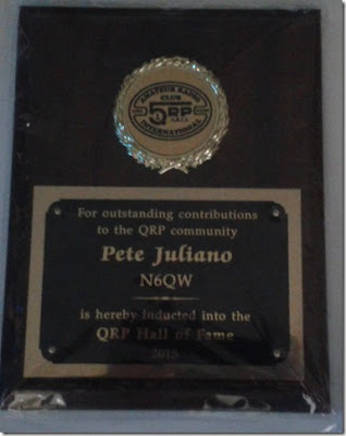
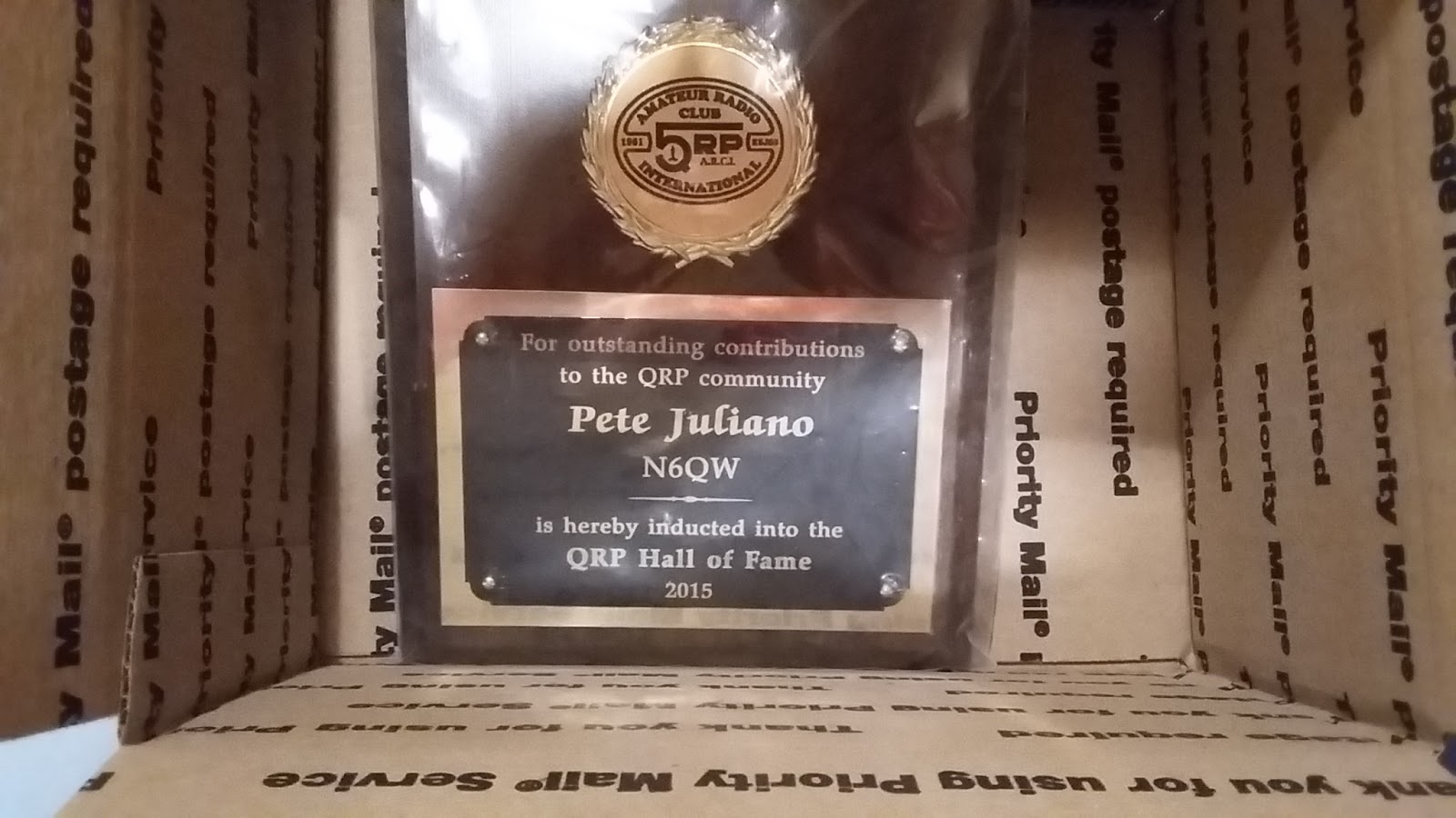
Pete Juliano’s Expulsion from the QRP Hall of Fame
First, I’d like to thank the many, many radio amateurs who sent in e-mails demanding that our friend Pete Juliano stay in the QRP Hall of Fame. Their outrage at his expulsion was palpable. They were angry and fired up. Many compared Pete Juliano to baseball great Pete Rose (who also got expelled from a Hall of Fame). They wrote to us from all around the globe. Several saw the action against Pete as yet another example of the deep divisions that are affecting modern society — several saw it as being connected to our recent Presidential election, and/or BREXIT.
Some writers took a diplomatic approach and tried to suggest ways that this ugly conflict might be ended — one fellow suggested that Pete try to redeem himself by agreeing to enter some kind of QRP 12 Step Program. Others got legalistically combative and said we should just “lawyer-up.”
A number of our correspondents took note of the seasonal nature of these kinds of events. Who can forget the April move a few years back by the New Jersey State Legislature to ban the use of soldering irons in the home? “This kind of thing always seems to happen in the Spring-time!” said one irate Juliano surrogate, “It is like Shakespeare wrote: ‘Beware the Ides of March’ — only two weeks later!” Another ham also spotted the seasonal nature of these stories and quoted from T.S. Elliott’s poem “The Wasteland”: “April is the cruelest month, especially the first day!”
We must point out that not all those who wrote were opposed to Pete’s expulsion — one writer said, “It is about time that that Pete “KW” Juliano got what he deserved! Good riddance!” (We have sent this e-mail to one of Pete’s Italian-American relatives in New Jersey for, uh, action.)
Several of those who wrote in support of Pete are prominent members of the amateur radio community (they will — if they follow our instructions — remain anonymous.)
One activist supporter said that Pete’s expulsion should lead to a street protest movement called “Pete’s Award Matters” and that the chant at demonstrations could be “NO JULIANO, NO PEACE!” Kind of catchy don’t you think?
Anyway, we sincerely hope you have ALL figured out what was going on here. For those who have not, and for all those who wrote in, let me complete the tradition by saying it: “April Fool!”
We’d like to thank all who participated in this long-standing amateur radio tradition. Special thanks to Preston Douglas and the QRP-ARCI for putting up with all this. (Tony Fishpool told us that he knew this couldn’t be real, because someone as nice as Preston Douglas would NEVER expel anyone.)
SolderSmoke Podcast #195: (We need some help!) BITX, 60, SSB History, Tribal Socketry

SENDING IT BACK
SolderSmoke Podcast #195 is available. Link appears below (scroll down)
We’ve got a problem: Pete Juliano and the QRP Hall of Fame 🙁 PLEASE HELP!
BENCH REPORTS
Pete Releases Smoke (wiring harness)
Pete’s DifX on 60
Architecture and Dual Conversion (uBITX: uses ALL THREE clocks on the Si5351)
The Big Kahuna
ON HACKADAY with Philco SB100 SEE! QRP!!!!!
BITX60
Cap Stack Hack mod (with leads)
Let the smoke out of an Si5351 (shorted output) Several actually.
(Same day delivery zone for Amazon — but no drones or parachutes yet.)
Installed scanning switch
Observations on 60. All the weird bands have a 6 in them: 160, 60, 6
The good: 100 watt limit, wire antennas
The bad: Kind of cliquish– like 75, not much of a CQ band. Channels. Not much activity.
The bad: Kind of cliquish– like 75, not much of a CQ band. Channels. Not much activity.
Met Josh KE8CPD on 40. BITX 40!
TRIBAL KNOWLEDGE:
Socketry: How to keep BNC jacks from spinning loose?
Do you heat shrink?
Feel Tech Sig Gen might not have blocking cap at the output.
Speaking of which, when I spoke of the Ne602, I mostly meant blocking caps, not bypass caps.
How come they don’t have a cable TV channel devoted to radios? They have HGTV? Why not HBTV?
REPORT FROM WINTERFEST
Bad weather. Tailgaters wimped out!
Combined forces with Armand WA1UQO.
Met up with Charles AI4OT.
Acquisitions: 1/4 phono jacks, carbon mic, vero board, disc caps, weather radio,
LARGE collection of Electric Radios from Armand. Wow.
Electric Radio notes: 1st Fifty Years of Sideband 1991 articles by Jim Musgrove K5BZH
Why LSB on 75? — so AMers couldn’t follow to top of band
W2, W6, W8s liked phasing, W3, W4, W0 more into filter rigs.
Early SSB guys turning on carrier and talking AM hams into SSB RX.
Kelvinator Refrigerator rigs.
A reading on the homebrewing of SSB rigs.
Tony Fishpool on QSO Today! Pete mentioned prominently.
Good Hacks from ND6T on BITXHacks, Stockton Bridge
MAILBAG
Pete’s 60 Meter DifX
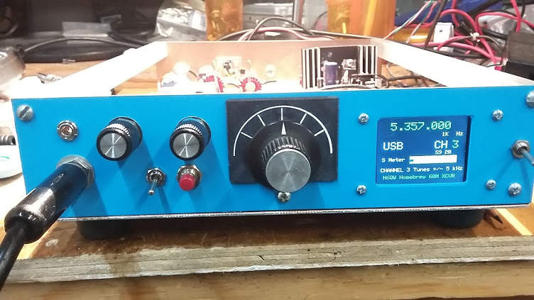
Oh man, run — don’t walk — to the N6QW blog and check out Pete’s amazing 60 meter DIFX transceiver. DifX is another N6QW contribution to the lexicon: it refers to a transceiver that has an architecture DifFERENT from that of our beloved BITXs. Pete means no disrespect to the BITX — he just sees the value in sometimes doing something different. I understand this completely — I myself am on my FIFTH BITX (three scratch-built and two modules) and definitely felt the need to do something different. (That’s why I built the OLED NE602 rig.)
Once again Pete Juliano shows himself to be a man ahead of his time: Anticipating FCC approval of a VFO tune-able segment in the band, Pete has made Channel 3 on his rig tunable with a rotary encoder. Hopefully, we will all soon need this. Pete is already there. FB OM.
My reaction to 60 meters has been very similar to Pete’s. We will talk about this on the next podcast (this Saturday).
Pete’s blog has a great description of the new rig, complete with a really nice video. Check it out:
http://n6qw.blogspot.com/2017/03/a-new-line-of-transceivers-difx_23.html
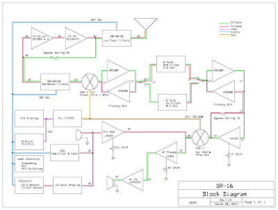
N8NM’s SR-16 Hallicrafters Tribute RIg
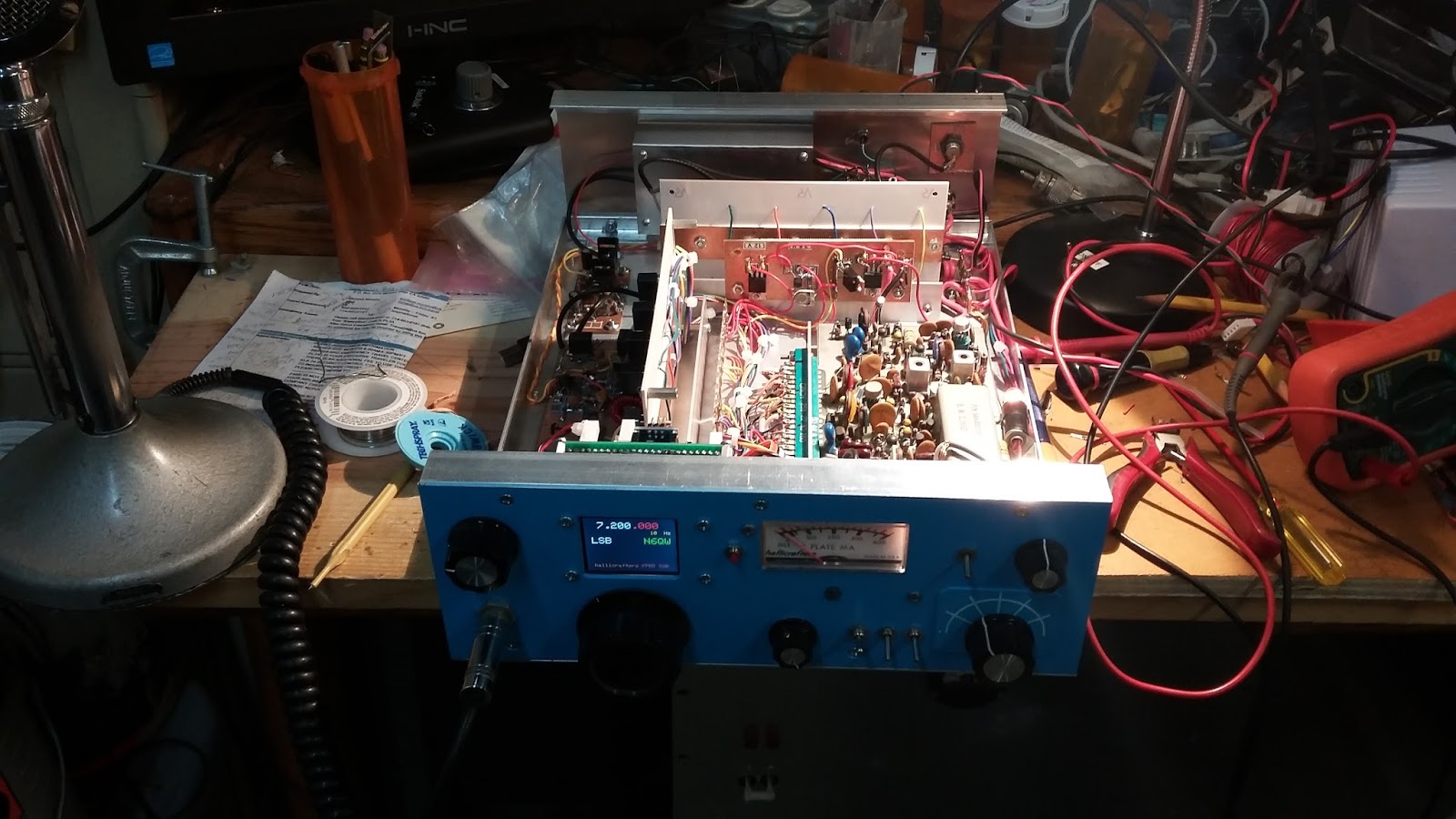
Bill, Pete:
The rig is loosely based on the Hallicrafters SR-160 transceiver, since I’m using a RD16HHF1 in the final RF, I’m calling it the SR-16. It’s a tri-band rig covering 80, 40 and 20m. Architectually, it’s similar to Pete’s JBOM, which is partially coincidental (thanks for sharing the article, Pete!) The heart of the rig is the W7ZOI hybrid-cascode IF, a really slick circuit that really makes the rig a joy to use.
Frequency generation is handled by the ubiquitous Arduino/Si5351 combo and a sketch based on Tom, AK2B’s “Multi Function VFO”, to which I added functions for selecting the appropriate bandpass and IF filters, generating CW, RIT, and dual VFOs (with split functionality), the state of which is saved in EEPROM when the rig is powered-down.
The rig’s just about finished – I’ve got the remaining parts ordered and hope to have it on-the-air soon.
73! – Steve N8NM
Ken G4IIB’s BITX Journey
The work of Ken G4IIB has been on this blog before — he helped many of us make use of the amazing RTL-SDR Dongle SDR receivers. He has recently turned his attention to the BITX40 Module and offers some great ideas for testing and for modification. Ken’s description of the smoothness of his audio adds a very evocative term to the SolderSmoke Enhanced SSB lexicon.
Hi Bill, Pete
Many thanks for your respective responses to my plea for help in setting up SI5351 derived BFO to my BITX40 board. You were both on the money.
Pete suggested that I had too much gain in my HB amplifier from the SI5351 output to the modulator and indeed that proved to be true. Once sorted I also noted that I was getting extra hiss on switching to one of the sidebands as you pointed out Bill this proved to be due to incorrect placement of that particular BFO frequency.
These BITX40 boards that Ash Farhan has developed and released to the world wide community of Radio Amateurs are worth every penny. Because they are so hackable (not just the circuitry but now the Raduino code also) it means that you can tailor it to your specific specification and in the process you are likely to learn new stuff and make new friends. I describe my BITX40 incarnation and experiences below:
Upon first firing up the BITX I was getting quite a lot of mains hum from my PSU’s (I thought that at least one of these PSU’s was a quality item) but obviously not up to the job. I constructed a simple one transistor capacitor multiplier (this converted a humble 1000uF cap into a 1F cap) and the noise magically disappeared. By coincidence I note that Bill discussed this technique in a recent pod cast. Another advantage of this technique was that I got a 2V drop across the transistor so by running this on 13.8V I get 12V out so I run the PA section on un-smoothed 13.8V (this gives me 12 watts of RF out) and run the receiver section on the smoothed 12V output from the multiplier, happy days.
My thoughts were to turn my BITX into a multi band (several bands rather than all bands) rig and I figured that using high side mixing (running the VFO at 19Mhz (12Mhz + 7 Mhz) rather than the existing low side mixing (12Mhz – 7Mhz=5Mhz VFO)) would be a better option. For example running it on 17M would mean using high side VFO anyway. I also wanted the ability to be able to switch sidebands especially on the lower frequencies so that I could use the rig for Digital modes in my case this was to be achieved by coding the Arduino to run a BFO on one of the SI5351’s clk ports.
I bought my BITX prior to the release of the Raduino so I had already commenced (with the aid of a new found radio friend and RF mentor) coding an Arduino VFO/BFO using a UNO and SI5351. Like I said at the beginning once you let folk know that you are starting on a new and interesting project you start to engage the more practical members of the ham community and they just want to get involved and help. Yet another good reason to buy a BITX . We used code originally developed by Jason Mildrum NT7S and Przemek Sadowski SQ9NJE and tailored it to suit the BITX40 and our requirements. This include high side VFO with frequency step adjustment and a BFO with long push BFO changeover. This meant that my BITX front panel should stay very minimalistic 2 knobs.
Getting the VFO to work was simple as the DDS socket was used and to better accommodate the high side VFO I modified the board by tombstoning caps C91 & C92.
Getting the BFO to work proved to be more problematic I was troubled with hiss and other noise. Words of wisdom from Pete Juliano when asked if I was doing something wrong were: ” No –it is just that we tend to think our projects are like Lego type building blocks where everything mates and snaps together. Sometimes more is required”. True Pete and that gives us the opportunity to learn new stuff!
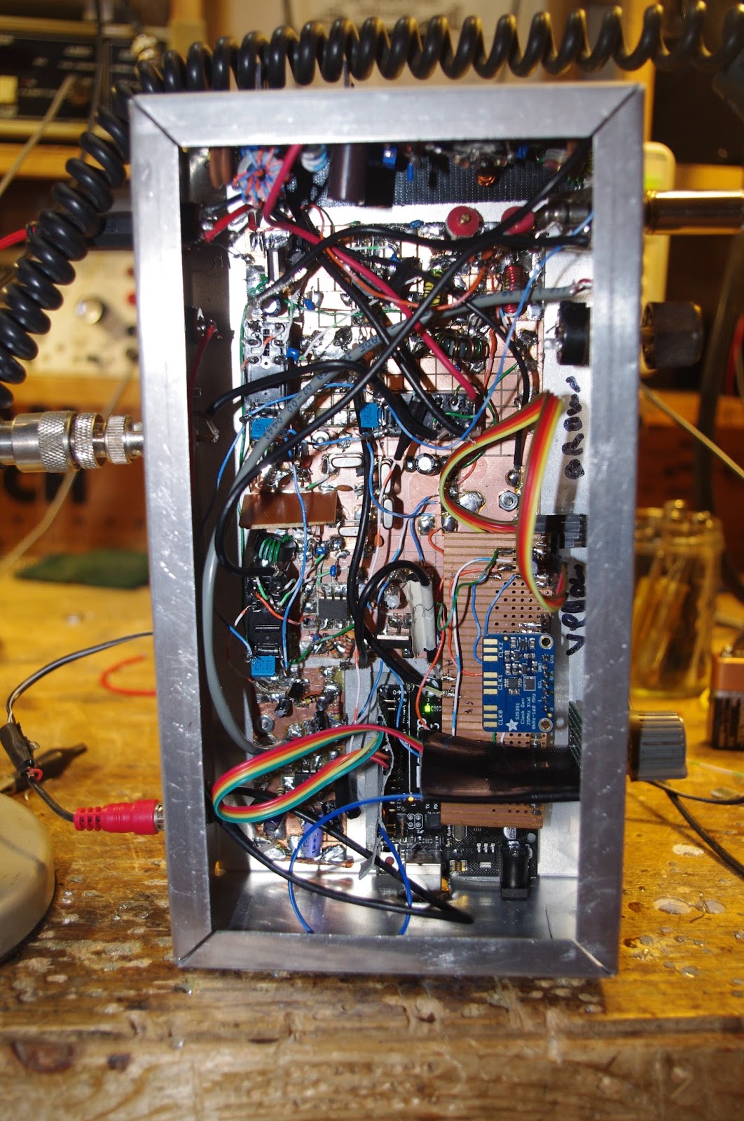
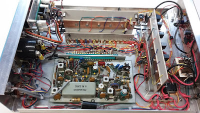
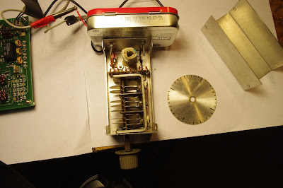
To cut a long story short I found that the best place to connect the BFO was on the modulation transformer T4 thus bypassing the BITX BFO stage altogether. I was also getting hash noise believed to be emanating from the Uno. At this stage my after market Raduino arrived from India. I fired this up and noticed that I was not getting any hash noise from it. This pointed us to a coding problem and the LCD refresh was altered on our code and the problem disappeared. Below a picture of the module showing the BFO connections to T4 and the large heat-sink with the IRF510 insulated from it. Also shown is the capacitor multiplier and a glimpse of the Raduino in the foreground. Not the most elegant box but this is likely to change pending further refinements. It’s still work in progress and this box gives me plenty of room.
The Raduino is a fantastic piece of kit for the money extremely neat and well thought out. The coding is comprehensive and innovative and works well. However, from an aesthetic and ergonomic point of view there were a few things that I personally did not like in terms of how it operates and performs. I could not get away with the potentiometer tuning, you can tune 50Khz of the band and then when you near the pot edge it increments/decrements and you can re-tune. I found this clunky to use and in addition the Raduino would hunt causing the last digit to increment then decrement causing an annoying warble on audio. In my opinion a Rotary Encoder would be better solution. On the plus side, although not mentioned on the Hfsigs web site the Raduino code does come with other functions such as changing sidebands by temporary high siding the mixer, a RIT, VFO B and CW tone. If you download and read the Raduino code from Github you will see this extra functionality which I believe you can make use of via extra switches (not supplied). The current Raduino code does not have any external BFO options as said it relies on the crystal BFO and temporally high siding the VFO to change from LSB to USB on 7Mhz.
The Raduino module itself is just too good and neat not to use. As I did not have the where for all to fully understand and amend Ash’s code I decided to use the Raduino but to load it with the code that we have developed for he Uno and Addafruit SI5351 board. This would give me near conventional tuning via a rotary encoder, adjustable step sizes via quick push of the encoder switch and USB/ LSB switching via long push of the encoder switch by virtue of the SI5351 generating the BFO frequency. I have retained a copy of Ash’s Raduino code just in case I wish to revert to it. I put a new header on the Raduino P3 connector so that I could connect a rotary encoder and use the 2nd clock output and then changed our code to run on a Nano. I had to add a correction factor in the code to cater for calibration differences in the SI5351’s (in my case 1.21Khz).
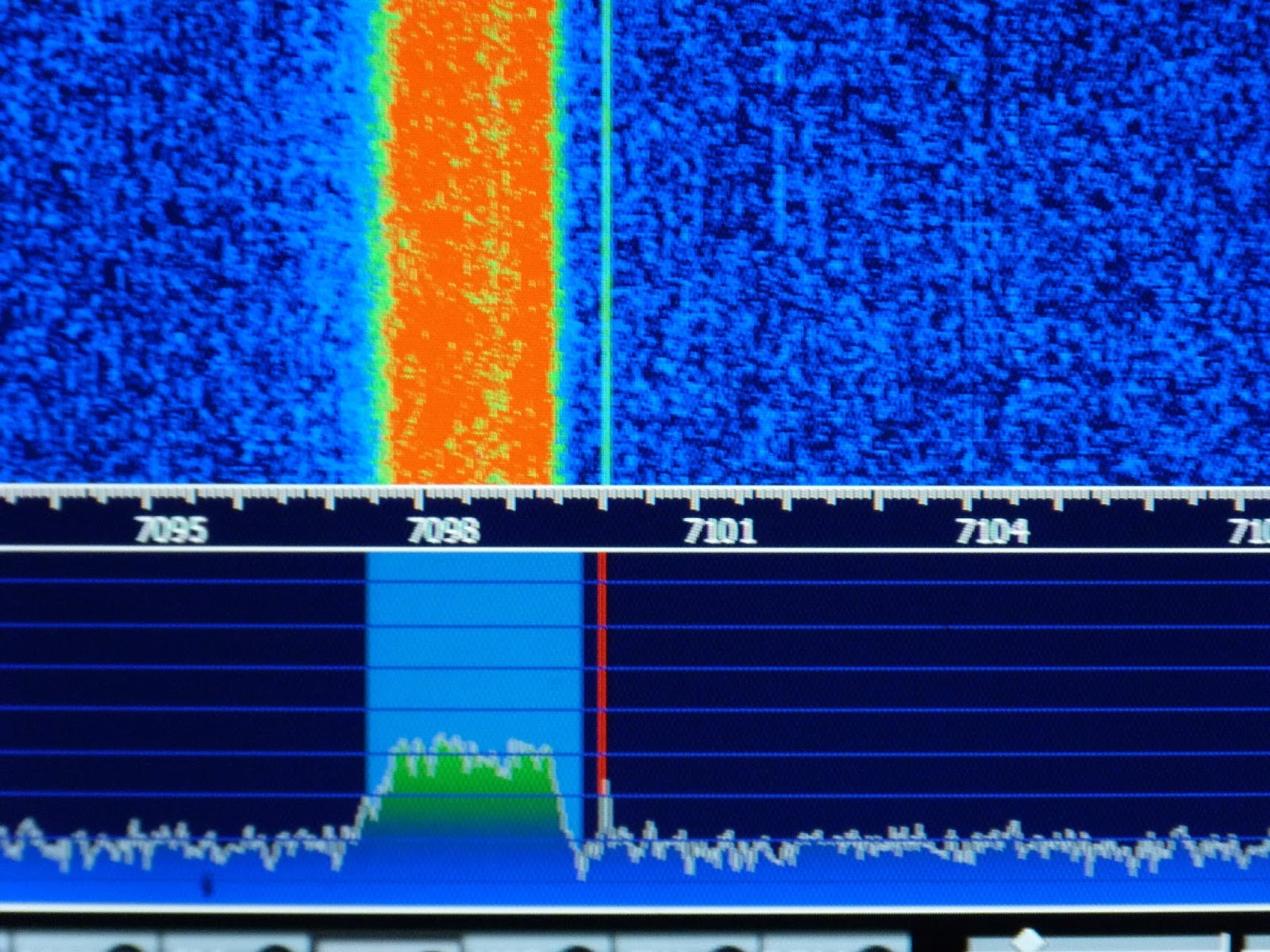
As previously indicated I had a little trouble arriving at the correct BFO frequencies I found that 119940 and 119970 gave me LSB and USB respectively for my high side VFO (19Mhz) if you use low side VFO (5Mhz) then these would be reversed. We further refined these frequencies by injecting white noise into the mic amp and looked at each transmitted sideband on my RTL-SDR dongle via HDSDR (a useful piece of test equipment). By adjusting the carrier trimmer to show the carrier in the extended HDSDR spectrum display we could see how much to move the BFO frequency to best occupy the crystal filter pass band, see image below. This frequency adjustment being achieved by a coding change. The frequencies I consolidated on to cater for my particular crystal filter are 119941 LSB and 119969 USB. We then nulled the carrier back out. My audio is now as smooth as a maiden’s inner thigh, trust me the image will follow!
So now I can get on and build an AGC and think about some sort of S meter. As for putting the BITX on other bands, whilst I now have a VFO capable of going anywhere, I would need to address band pass and low pass filter and switching arrangements. I may still experiment with this but, as pointed out by Ash in a recent pod-cast, the BITX single superhet design is not best suited to multi band operation but can be quite easily changed to operate on another single band. He also indicated that he was developing a dual superhet with consideration for multi band operation. Once released this might be a better option for multi-band use.
In the mean time folk should just get a BITX40, hack it to bits and share with us their customised versions.
Ken G4IIB
SolderSmoke Podcast #192 FPM Rig, BITX Module Madness, HRO Al Fresco, Boatanchor Day, Mailbag
SolderSmoke Podcast #192 is available:
http://soldersmoke.com/soldersmoke192.mp3
N6QW COMPLETING AN ORBIT TOMORROW!!!! Happy Birthday Pete!
Shortwave Woes: Deception and Disappointment!
Voice of Vietnam! But it is from Cyprus Creek S.C.
Radio Athmeeya Yatra in Punjabi! but it is in Nauen Germany. Yuck!
Sort of like these 9 cents per minute on-line relay ham stations. Yuck I say!
You know you are a hardcore homebrewer when a near empty can of Deoxit makes you nervous, so you order more, just in case.
Bench Reports:
Pete:
FPM FPM FPM!!! Tell us about it!
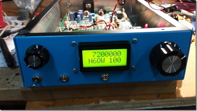
BITX 40 Module in Juliano Blue
Explaining the BITX 40 to the local club.
CULTURE SHOCK! Plug and play vs. Hardcore Homebrew.
Bill:
An EXTROVERTED BITX 40 Module
QRO with 24 volts on the Drain: 20 watts out. Heatsink upgrade, Chris KB4PBJ Thanks.
Analog Readout — Dymo tape and a Sharpie arrow
REVERSE POLARITY PROTECTION Where the perfect is the enemy of the good enough.
HRO no longer AL FRESCO Boxed up. Thanks Armand. Thanks Tim Sutton. Still working on AM receiver. Not inhaling very well.
Boatanchor Day: Fixed HT37 and hurt my back. Really. Got 160 meter station going. Changed ball bearings on CW key.
Next project. Another BITX 40, but perhaps for 160, 75 and 60 with Si5351 and plug-in filters.
Sideband History: THE SIDEBAND SUZY AWARD. Pete deserves this. I say we revive it.
LEX: Al Fresco. And Tim Walford calls them “Blackbox rigs” not “rice boxes”
HB2HB contacts. Often with guys who built their linear. I say that counts Too!
MAILBAG
Beauty and the Beast: Pete’s Beautiful BITX 40 Module and My Ugly Version

As the proud owner of what has to be one of the world’s UGLIEST BITX 40 Modules. I feel somehow qualified to declare Pete’s version of this rig to be one of the world’s most beautiful. His is resplendent in Juliano Blue — mine has no paint at all. His features glowing numerals — mine has nothing but Dymo stickers and an arrow drawn with a Sharpie marker. Bravo Pete!

Pete Juliano Adds Yet Another Great Word to the Homebrew Lexicon
We’ve talked many times about the pleasures associated with a rig that is still just a collection of parts and boards, all still spread out on the workbench, unboxed, perhaps held together by clip leads and bits of duct tape. They seem to sound better this way. This is the condition under which we experience that magical moment of “First Signals” (similar to First Light with a new telescope).
We haven’t had a concise way of describing this (note my long-winded description above). Well, this morning the Sage of Newbury Park has, on his amazing blog, provided us with the words that we have so long needed:
Al Fresco!
That’s it! Perfect. When a new rig is put into operation in this way, we will henceforth say that it is being run “al fresco.” Thanks Pete!
Check out the blog post that gave us this wonderful phrase:
HB2HB! Pete Talks to Famed SSDRA Project Builder Jeff Damm WA7MLH
 |
| Jeff “Roadkill” Damm |
Wow, THE RADIO GODS HAVE SPOKEN (TRGHS). Pete gets on 40 with his new-old FPM5 homebrew rig and works homebrew legend Jeff Damm WA7MLH, who was also running a homebrew SSB rig. HB2HB! For those of you who don’t know, Jeff is the guy who built many of the inspirationally ugly rigs in Solid State Design for the Radio Amateur. Pete’s second QSO was with SolderSmoke podcast listener K7ADD. TRGHS!
Hi Bill,
Was on 40M yesterday with the FPM5 rig and after finishing a QSO was called by WA7MLH (Jeff Damm –the road kill guy and protégé of Wes Hayward). Jeff was operating portable 7 in NW Montana running a homebrew 40 Watt SSB transceiver off of batteries being charged by a solar panel. Now that is real radio. I thanked him once again for sending me a goodie box about 5 years ago and am still using those parts.
Later after another QSO was called by K7ADD, Ben, and he couldn’t wait to tell me he was a long time SS listener and stated listening to SS made him take a whole new interest in ham radio –especially building stuff.
So you never know.
Pete
Two Gel Cells and a Heat Sink — BITX40 Power Hack
I blame Pete for this. And Farhan. Pete has been leading us astray with all his talk of high power linear amplifiers (“Two 813s kid, that’s all you need!”). And Farhan practically pushed us beyond QRP limits by placing a separate DC power connector for the IRF510 final amplifier on his new BITX 40 Module board. Farhan writes:
There are jump-points from where you can add more modules like the DDS, more bands, better audio amplifier, etc. Imagination is your limit. You can separately increase the power amplifier’s supply voltage to 25 volts to be more than 20 watts of power : You will have to add a better heat sink. The mods are on the way! (from hfsigs.com)
A while back Chris KD4PBJ sent me some very nice heat sinks — one of those would fit quite nicely on the PA side of the BITX40 board. And I just happen to have two 12V Gel cell batteries. One will power the board and the two together will power the IRF510. With 20 watts out to my dipole I feel confident that I will WIN the upcoming ARRL Phone Sweepstakes (in my category: Homebrew VFO, Northern Virginia).
SolderSmoke Podcast #191 RIGS! REAL RIGS!, BITX40 Module, EMRFD, MAILBAG

SolderSmoke Podcast #191 is available:
http://soldersmoke.com/soldersmoke191.mp3
TRAVELOGUE AND FAMILY DOINGS: Pete son’s wedding, Billy’s Birthday, Gonzalo safely home in the Dominican Republic, MORE BEARS IN THE SHENANDOAH WOODS
BIG NEWS: EMRFD LIVES ON! Three cheers for Wes and for Tom Gallagher of the ARRL.
BENCH REPORTS:
PETE: FPM Rig. Some Halli history. A TRUE RIG! Working Japan.
WITH 600 WATT LINEAR AMPLIFIER!!!!!!!!!!!!!!!!!!!!!
New FEELTECH Sig Gen.
BILL: Farhan’s BITX Module
Built to Mod, built to get you started in homebrew
Very impressive. BITX in miniature. But completely recognizable.
REMARKABLY stable.
Farhan personally checking each one.
Ladies collective doing toroids. DONATION money bought them some Diwali candies!
VFO Drift: Will NP0 SMD caps and lower current help enough?
My Analog VFO — BANDSWEEP
QRPppppppppppp with REX’s Hamfest Buddy. Thanks Rex and Bob Crane.
HB2HB with KW4KD
MAILBAG
Jan’s Netherland Mate Mighty Midget
Charlie’s Kiwi DSB
Steve, Donald Fagan, and Jean Shepherd
Rob VK5RC repairs Tek Tube ‘scopes
Colin M1BUU Si5351 superhet
Denis Klipa and NRL 3538
Jonathan M0JGH Wizard of Wimbledon Matchbox rig
JH8SST Simpleceiver
Peter Parker Vk3YE Reviews Book
Peter GW4ZUA Welsh LBS
Michael Rainey helping hobbyist in Germany with tuning forks.


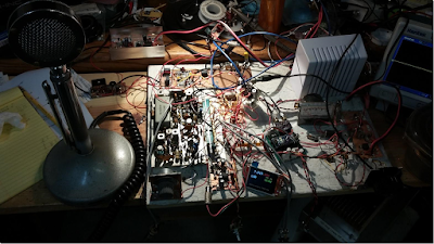
It’s Ugly, But It Gets You There: Pete’s Latest Rig
That, my friends is an extreme example of what we mean when we use the word “rig.” This magnificent machine sent Pete’s melodious voice across the mighty Pacific several times during the recent CQ WW contest.
Pete wrote to Jun:
Hi Jun,
This weekend is the CQ World Wide SSB contest and I just worked three JA stations on 40 Meters. The time 1400 UTC. I must confess that I was using 600 watts to my droopy dipole but they came back on the first call. So there are paths open and perhaps 600 watts was overkill but the timing seems like it works for a good path to the west coast. Along the way I also worked a station in Hawaii (KH6).
See if you can find some 813 tubes as they make a great grounded grid linear amplifier tube and a pair will give you 600 watts. see http://www.ohio.edu/people/
The rig I was using is shown below. The mainboard came from a Hallicrafters FPM 300 (late 1960) to which I added the Rx Tx Mixer (SBL-1), my stock 2N3904 bi-directional amp board, the 2N2222 + BD139 driver stage using the EMRFD circuit and a 2SC2075 final which gives about 3 watts. This in turn drives an intermediate SS amp to 100 watts and then the SB200 to 600 watts. The FPM 300 used a 9.0 MHz IF frequency.
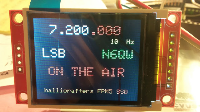
Of course no rig today from N6QW would be complete without a Si5351 and the color TFT display. Rounding this out is an LM386 audio amp stage. Cosmetically the rig doesn’t look pretty but sure works well.
73’s
Pete N6QW
(The comments about the 813s are kind of SHOCKING, coming from a member of the QRP Hall of Fame!)
Hacking the Hackable BITX 40 Module: VFO is the Way to Go!

I am having a lot of fun with Farhan’s new BITX 40 Module. I think I’m doing exactly what Farhan intended people to do with this rig: work on it, modify it, improve it.
I’ve been working on frequency stability. I was, I admit, skeptical from the start about the stability of a thumb-sized, SMD, varactor-tuned VFO with a ferrite or iron powder toroidal coil. Don’t get me wrong — it worked. But it drifted. It seems to me that it would be asking too much to expect a VFO like this to be drift-free. (But I may be wrong — are there any SMD, varactor-tuned VFOs out there that DON’T drift?)
First I thought it might be the 9 uH metallic core toroid. So I replaced that with a 10uH choke — no ferrite or iron powder in there. That seemed to help a bit, but SSB QSOs would still quickly drift into Donald Duck chatter. Then I thought it might be the varactor diode. I let it warm up. A lot. Still, it drifted. Then I thought it might be the trimmer cap, so I took it off the board. No change. During this process I noticed that even slight pressure on the board caused the rig to shift frequency. I began to suspect that the drift was just structural — a consequence of the physical characteristics of the SMD parts and the board. To get VFOs stable I’ve had to build them big: 10 X 10pf NP0 caps to make one 100 pf cap, large air-core coils, and big sturdy variable caps. I’d isolate the frequency determining elements in a box separate from the powered components. This little VFO just looked too small to be stable.
So faced with drift, at first I asked myself, “What would Pete do?” I took an AD9850/Arduino combination off the shelf and plugged the output into the “DDS” jack Farhan had placed on the board. I removed the 10uH choke. Viola! With the DDS tuned to 4.7 – 5 MHz, the receiver worked great. I briefly tried to updated the Arduino code to take into account the 12 MHz IF (so I could get an accurate frequency readout), but ran into the old painful Arduino IDE problems: Now it is claiming there are library problems. Not wanting to suffer through another round of digi-agony, I left well-enough alone. I used the DDS with the old code for one day.
But of course, I was not satisfied. Attaching a DDS or PLL synthesizer to the BITX 40 Module just didn’t seem right. Heck, it was kind of like just hooking up my FeelTech Chinese sig gen to the DDS jack. Farhan’s rig is simple, beautiful and ANALOG. The parts are small, but you can see them. You can put your scope probe on the collector of Q7 and see what is going on. DDS or PLL. It is a REAL HARDWARE-DEFINED RIG. So I decided to build a VFO. Pete calls VFO’s “grief machines” but for me, the grief machines are those little Arduino beasts. To each his own.
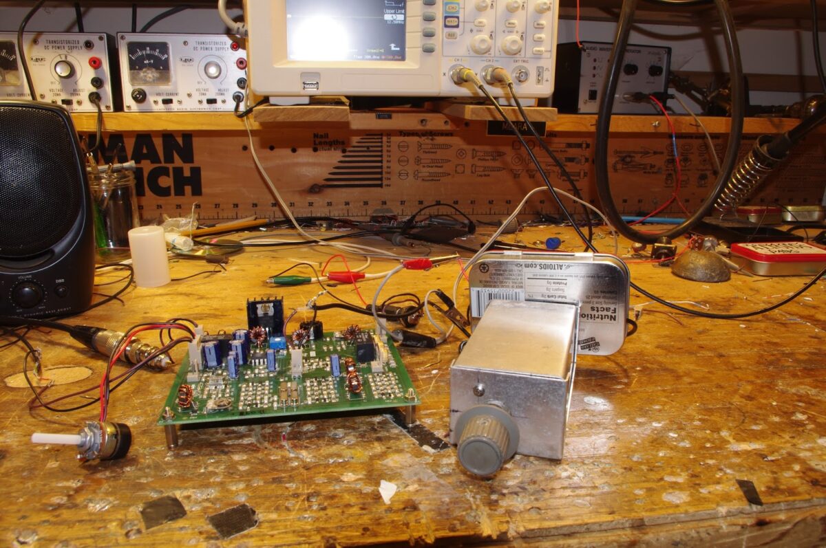
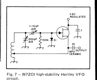
When I build a VFO, I start with the variable capacitor and the reduction drive. I found a nice one (with reduction drive) in my junk box. I tunes from 40 pf to 56 pf. I decided to use the super-simple Hartley circuit presented by Wes Hayward W7ZOI in SSDRA (page 34, fig 7).
I went with a 4.4 uH air core coil (wound on a cardboard tube from a coat hanger). Consultation with on-line resonant frequency calculators showed that I’d need to put about 180 pf in parallel with the variable cap. For this, I used a bunch (maybe 10?) of small value NP0 caps in parallel. This really helps keep the VFO stable.
As I did with my HROish receiver, I put the coil and the caps in one box, with the MPF-102 and associated parts in an attached Altoids tin. Everything was glued and bolted down very solidly.
I only built the actual oscillator stage — I decided to use the buffer amps on Farhan’s board.
The oscillator started right up. I had to add and then take away some turns on the coil to get it to run in the desired range. Then I plugged it into the DDS jack — the receiver was working immediately.
I noticed, however, that it seemed a bit less sensitive than it had been with the AD9850 DDS. And when I grabbed the wire going into the DDS connector, audio output jumped dramatically. It took me a few minutes to figure that out: I think the output from my VFO was not adequately turning on the diodes in the diode ring. When I grabbed the wire, I was putting a lot of noise into the mixer port, probably turning the diodes more fully on (but also letting a lot of noise through).
Fixing this problem part was fun: Looking at the BITX 40 schematic, I saw that the two 1000pf feedback caps in the original oscillator were still in the circuit. I figured those caps would be sending a lot of my VFO energy to ground. So I fired up my hot air rework station and deftly removed C91, the 1000 pf cap that is connected to the base of Q9. Instantly the receiver started inhaling as it had with the DDS VFO. That was a very satisfying fix.
This whole VFO project was very satisfying. It was all done in one day, and all the parts came out of my junk box. I think I ended up with an LO frequency source that matches up in a pleasing way with the analog circuitry in Farhan’s rig. And here is bonus that I think is just what Farhan had in mind: this kind of circuit adds a definite homebrew element to the module rig.
I found that this external VFO improved stability significantly. I don’t know if it is as stable as the DDS, but with the external VFO the receiver no longer drifts away as I listen to SSB signals.
The Last Hallicrafters Transceiver…REBORN! TWICE!
Pete Juliano and his colleague Giovanni Manzoni led me this morning to the happy land of Hallicrafters hybrid nostalgia.
It all started with Pete’s latest blog post:
http://n6qw.blogspot.com/2016/10/more-junk-box-rigs.html
I admit that I had never even heard of the Hallicrafters FPM rigs. Pete’s (uh, I mean Giovanni’s) video show’s Pete’s junk-box rebuild of the old rig. Very nice. Note the presence of the Si5351…
I needed more background info, so I turned to YouTube. This led me to more old friends: Dale Parfitt W4OP has a really nice video of his rebuild of the Halli FPM rig (see above). From his video we learn why Dr. Juliano prescribed a dose of Si5351 for the patient: Dale tells us that VFO instability was a major problem with this rig. Dale fixed his with the addition of an X-Lock board from yet another friend of SolderSmoke: Ron G4GXO of Cumbria Designs.
Dale really out-did himself by building an add-on accessory box for the FPM. Very nice. I especially liked the addition of the W3NQN passive audio filter for CW. I always have misgivings about adding audio filters to Direct Conversion receivers — this will reduce QRM, but you are still listening to both sides of zero beat. But when you add a sharp CW audio filter to an SSB superhet you will end up with true “single signal reception.” FB Dale.
Please send Pete Juliano and Giovanni Manzoni some positive feedback and words of encouragement. Please urge them to keep up the good work on the blog and the videos. Theirs is sometimes a lonely task — without feedback it can sometimes seem like putting messages in a bottle and throwing them into the digital sea. Please let them know that their work is being seen! Leave some positive comments on Pete’s blog. (No snark please — The Radio Gods will retaliate if you harsh N6QW’s mellow.)
JH8SST/7’s Build of Pete’s Simpleceiver
Beautiful.
Makes me want to put S-meters in my rigs.
More on Pete’s design here:
http://n6qw.blogspot.com/2015/09/simpleceiver-40m-ssbcw-receiver-and.html
GW4ZUA’s “Let’s Build Something” Receiver
The LBS project of Pete and Ben continues to inspire homebrewers all around the world. Check out the video of GW4ZUA’s version. Peter GW4ZUA writes:
Hi Pete,
Thank you for your kind words,
I suppose it started with a knob and a pointer to know (guess) where you were on the band, probably most radio builders did the same, and some still do, but as long as it worked you were very satisfied, what a marvelous feeling when you switch on and those electronic components do their job and deliver the goods……amazing.
So time moves on you get better at building and technology gives you a hand, LCD displays, homebrew frequency counters,cheap components, wow now you Know where you are on the band.
Then I saw your rig with a colour display and DDS “I gotta get me one of these.”
I watched most of your videos, Your “easy going, down to earth manner” made it look easy to do.
I love the internet, without it I’d probably still be using knobs and pointers, there are is a wealth of knowledge available to those lucky enough to have access. I also love email, as you can now contact people who are willing to share their projects and give advice.
So the LBS well it certainly works, so few parts but they are all eager to please, with the display (did I mention the display) it is a project you can be proud of.
A big thank you to you and Ben for the project,
I don’t know if it will ever go in a box as I just love to look at it and I’m amazed at what comes out of the speaker.
Regards to you all……….
73’s for now. ………..Peter (GW4ZUA)
————————
As is well known, I’m more of a knob and pointer guy myself, but I understand the attractions and advantages of the glowing numerals. And I definitely sympathize with Peter’s comment about the beauty of an in-boxed rig.
Oz JOO : An Australian Mighty Mite with 3D Printing
Hi Bill & Pete,
I have the JOO – joy of oscillation! The transistor is a 2N3053 with a clip on heat sink, but I don’t think that I really need it. Output power +22dBm or 160mW. When I tested it on a Comms test set at work, I found that the harmonics were about 12dB to 15dB down and I stopped looking at the 10th harmonic. Not good.
Fitting the 80m low pass filter (salvaged from another project) brought the harmonics more than 50dB down.
The coil former is a 31mm diameter and 3D printed by one of the guys at work. The material is PET – the material they make soft drink bottles from. After we printed it, I put it in a microwave oven with a glass of water. 30 seconds and the water got warm and the coil former stayed cool.
I haven’t had a contact yet, but maybe in the next few weeks.
The next project is an 80m CW transmitter based upon the Goodfeller transmitter from QST 1946. It requires a inductor in the pi coupler, 1.5 inch diameter, 32 turns at 20 tip; but where to get one of those these days – wind your own.
I got the guy at work to also 3D print me a coil former with a spiral thread around the outside with a 20tpi pitch for the wire to lay in. Some hot glue and the coil is ready.
Now that I have finished all 189 episodes and two specials, my days are empty. Please make some more.
73 de Peter VK2EMU
Hi Peter (great name BTW),
Congratulations –really liked your build – top drawer! 3D printer access WOW – now if I could only get my 3rd son (Mechanical Engineer) to build me one of those machines.
The 3D made coil form is perfect for a VFO and follows the principles set down by Doug DeMaw W1FB (SK) about keeping the coil supported at both ends and away from metal. Bill needs a coil like that to mate with his HRO dial mechanism –and follows something old (dial) something new (coil).
73’s
Pete N6QW
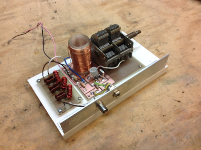
First Signals from the “Armand HROish” Receiver

I’ve been kind of busy lately with other things, but I have managed to squeeze in a few minutes most days to work on my latest receiver project. I call it the Armand HROish receiver. Armand WA1UQO sent me the big National HRO-style dial and gear box, and he was there at the Manassas hamfest when I bought the dual variable cap that now serves in the front end pre-selector.
I went with a 455 kHz IF. The idea is to have a receiver that tunes from around 6.5 MHz to around 8 MHz so I can do some shortwave listening AND listen to 40 meters.
So far the filter consists of three IF cans (one small transistor can and two larger tube-type cans). The small transistor can was given to me by Michael Rainey AA1TJ – thanks Mike. Doug DeMaw suggested this use of IF transformers in his “Design Notebook.”
At the front end I have a tunable dual tuned circuit filter followed by a 40673 amp.
The mixer is an SBL-1.
1st and 2nd IF amps are a 23 db 50 ohm termination insensitive amplifiers.
I have a second SBL-1 that will be the product detector, but I haven’t built the BFO yet. So today I hooked up two 1N34A diodes in voltage double config and — with a bit of AF amplification, got the receiver inhaling with a diode detector. I could pick up Radio Canada. Then I heard SSB sigs on 40. With no BFO, I decided to put my sig gen on 455 kHz and just wrap the lead around the IF cans. It worked — I could listen to SSB and CW sigs. Very satisfying.
Still to do:
— BFO and product detector.
— Work on AF amp.
— Get my CM-455 crystal mechanical amp in there with some relays around it so I can switch from narrow to broad via the front panel.
Lots of soul in this receiver: All parts either 1) came out of the junkbox, 2) were gifts from friends, or 3) were recent hamfest purchases. The HRO dial from Armand and the IF can from AA1TJ. The 455 kHz filter idea came from Doug DeMaw, the VFO circuit from SSDRA. The VFO base is from Whole Foods and the whole thing is built on a kitchen cutting board. It includes a 40673 and germanium diodes. The VFO amps are in Altoid tins. It will, when finished, go into a big metal box given to me by Tim KI6BGE and shipped east by Pete Juliano. And when I was working on the 1st mixer, I accidentally pricked my finger and a drop of N2CQR blood went onto the breadboard. Of course, I left it there. SOUL!
The Radio Gods are apparently pleased: In the first hour or so of listening, I was rewarded for my efforts when I managed to hear Tim WA1HLR on 40 AM describe his troubleshooting of an old piece of gear. TRGHS.