Pete Juliano’s Presentation to the 2020 G-QRP Club Convention — Building SSB Transceivers

It is a great day my friends. G-QRP has posted on YouTube the presentations made at their 2020 convention. TRGHS! Above you can see the awesome FB contribution of Pete Juliano N6QW. I watched it live on Zoom, but have been waiting patiently for the opportunity to share it with SolderSmoke readers and listeners.

There are many other great videos of convention presentations on the G-QRP YouTube channel. Here is the link to the channel:
Be sure to subscribe and give many “thumbs up” to the presentations.

I see that our friend Alan Wolke W2AEW has a presentation on the NanoVNA in that channel. FB Alan.

Thanks to G-QRP for running this event and for putting these videos on YouTube.

Adding 10 kHz of Coverage to My BITX 17

Solar Cycle 25 is underway. The Solar Flux Index and Sunspot numbers are up considerably. I have dusted off my old BITX17 transceiver. This time around I am using it in conjunction with a waterfall display provided online by NA5B’s KiwiSDR receiver, which is located about 9 miles east of me. This SDR receiver allows me to see the entire 17 meter band. It was this panoramic display that made me pay more attention to the fact that the Variable Crystal Oscillator (VXO) that I am using in this rig prevented me from tuning the lower 10 kHz of the 17 meter phone band (18.110 — 18.120 MHz).

I use two crystals switched by a relay to cover the band. One is at 23.149 MHz, the other at 23.166 MHz. The crystal filter is at 5MHz. With a coil and some caps I could move the frequencies of the oscillator enough to cover 18.120 to 18.168 MHz (top of the band).

When I first built this thing, I kind of wrote off the lower 10 kHz of the phone band. I couldn’t get the oscillator to work that low, and I was already satisfied with the top 48 kHz. But the NA5B waterfall often showed SSB stations in that lower part of the band. I wanted to talk to them. So I started thinking about how to do this.
Looking at my schematic (above) I remembered that most of the frequency lowering was done by L1, a 3.2uH toroid. I figured that to go a bit lower, I would just have to add inductance. But I didn’t want to lower the frequency provided by BOTH crystals — I just wanted to bring the frequency with the lower crystal down a bit.

In my junkbox I found a 1 uH coil. I disconnected the lower lead of the 23.149 MHz crystal from its connection to the relay. I soldered the 1 uH coil between the crystal and the relay (see picture above). This moved the lower limit down to 18.087 MHz.

Now crystal one provides 18.087 – 18.144 MHz
crystal two provides 18.137 – 18.167 MHz

So now I have the whole phone band. Bob is my uncle. TRGHS.

This was a very quick and satisfying little fix. As Pete says WYKSYCDS: when you know stuff you can do stuff. Indeed. And as I re-build and repair gear that I built years ago, I am often reminded that as time goes by, we learn more. We end up knowing more and being able to do more.

I am also planning on rebuilding my 17 meter Moxon; this time I will make it better and stronger.

Adam N0ZIB’s Direct Conversion Transceiver

This is obviously very cool, but looking ahead I think Adam should think about adding one more mixer, changing the bias on the TX amps, and adding a mic amp. Boom: A Double Sideband Transceiver.

Pete wrote: When I was in the US Navy and a particular unit did something outstanding – the Command ship would raise the Bravo Zulu Flag for a job well. Don’t know if you can see it there in MO but I have raised the BZ flag to you. Outstanding and congratulations.

Bill and Pete:

Just finished a DC transceiver using Arduino nano, SI5351 (my sincerest apologies, Bill), diode ring mixer and lm386 audio amp. The transmit portion is a two-stage class AB pre-amp (from EMRFD page 2.32), which is driving an IRF510 final (biased at 2.08 volts) from Pete’s design. Output is about 5watts into a CWAZ low pass filter, based on the design from here: https://www.arrl.org/files/file/Technology/tis/info/pdf/9902044.pdf

I’m using a manual TX/RX switch which is doing multiple things. It brings the Nano A1 LOW, offsetting the transmit frequency 600 Hz for CW, grounds the audio input to prevent deafness (learned that one the hard way), and it engages a relay that switches the antenna from the receiver to the transmit, and also turns on the transmitter stages. Keying is through the first stage of the pre-amp.

I still have some tidying up to do, and I’m not sure the LPF works so well using two component inductors instead of all toroids, but I finished it today and made my first QSO into Ontario almost 1000 miles away. It’s been great fun!

73,
Adam
N0ZIB
Missouri

Diode Ring Magic

I continue to work on the product detector of my Lafayette HA-600A. This work has caused me to brush up on my understanding of how mixers really work.

I think one of the most interesting mixer circuits is the diode ring. With just four diodes and one or two transformers, this device manages to take an incoming signal and multiply it by either 1 or -1 depending on the polarity of the local oscillator signal. That is pretty amazing.

Alan Wolke W2AEW did an excellent video on this: https://www.youtube.com/watch?v=junuEwmQVQ8

Inspired by Alan, I took my most recent homebrew diode ring mixer (with transformers from Farhan, diodes from Jim W8NSA, and a PC board base from the CNC mill of Pete N6QW) and hooked it up to two signal generators and an oscilloscope. I had the local oscillator at 10 MHz and the signal oscillator at 7 MHz. You can see my results in the pictures (above and at the end). You can see the resulting difference frequency (3 MHz) in the broad up and down pattern. And you can see the sum frequency (17 MHz) signal in the faster oscillations. All you would need is some filtering to separate them out.
I really like the RSGB Handbook diagram (above). I think the bottom schematic with its crossed diodes really explains how the phase reversal takes place: when the LO turns on D1 and D3 (the horizontal ones), multiplication by 1 takes place. But when the LO turns on D2 and D4 (the crossed diodes), up goes to down and down to up, creating phase reversal, or, in math terms, multiplication by -1.

At a more basic level, mixing takes place whenever — in a non-linear circuit — one signal is controlling the gain or attenuation experienced by the other signal. A complex waveform results, a waveform that contains sum and difference products. A circuit like the diode ring, that alternately multiplies by 1 and -1, is non-linear in the extreme, and the multiplication is controlled by the LO. The results can be seen in the diagram’s complex waveforms, on Alan’s Tek ‘scope, and on my Rigol. And in those complex waveforms you can SEE the sum and difference frequencies. That is really cool.

SolderSmoke Podcast #226 The U.S. Election, Solar Cycle, uSDX, Hermes, HP8640B, SGC 600 Sig Gen, HA-600A, Mailbag

SolderSmoke Podcast # 226

http://soldersmoke.com/soldersmoke226.mp3

———————————-

About the U.S. election

————————————

Mars: Setting early, will have to shift to evening observation. Weather has been poor.

Sunspot Cycle 25 is underway — SFI 78, SN 32

The Gliessberg cycle


Pete’s Bench: #49, #50, uSDX, Hermes Lite


Bill’s Bench: HP8640B, Global Specialties Corp 6000 counter, Lafayette HA600A.


MAILBAG:

Peter VK2EMU Sent me copy of 1947 Handbook. Thanks Peter

Brad W1BCC Spotted 10 S-38s for 80 bucks on Craig’s list. What’s going on here?

Dale K9NN sent both Pete and I care packages with very cool part, including DG Mosfets

Stuart ZL2TW sent me Les Moxon’s Antenna Book. TRGHS. Moxon will be back!

Alvin N5VZH got his receive converter with a little Tribal Knowledge from SS.

GM4OOU The Bitsy DSB rig from Scotland

Peter VK3YE DSBto DC incompatibility SOLVED

Paul VK3HN’s Digital SWR and Power Meter and Low band AM TX VFO/Controller FB Videos.

VK2BLQ alerts us to article about Jac Holzman of Elektra Records.

AA0ZZ great message on assembler language and writing software the hard way.

On the Cover of The Rolling Stone (Almost) — Jac Holzman, Elektra Records, and Ham Radio

Thanks to Stephen VK2BLQ for alerting us to this. That is Jac Holzman of Elektra Records fame, pictured in a recent article in Rolling Stone:

The Rolling Stone caption says he is in his “home studio,” but we recognize it clearly as a ham shack.

Here is another article about Jac:

ARRL reports that his callsign was K2VEH.

Hey, Pete plays guitar. So does Farhan. Should we have our people call Jac’s people? Maybe do lunch?

Solar Cycle 25 – The Gleissberg Cycle Dashes Hopes for a Big Solar Max

In our last podcast Pete N6QW expressed pessimism about Solar Cycle 25. I pushed back, asking Pete to stop with the negative vibes. Well, as always, it turns out that Pete was right.

Hack-A-Day today has a nice post about solar activity. They note that cycle 25 is likely to be much like cycle 24 — not great, certainly not as great as cycle 19. Pete operated during that magnificent event — I was born during cycle 19 — TRGHS.

While Pete was right about the poor prospects for cycle 25, I doubt that he knew WHY it will be so tepid. Well friends, here is something else for us to worry about: THE GLEISSBERG CYCLE. This one is not 11 years long. It is 87 years long and we are in the declining phase right now. So apparently it will be future generations of ham radio operators who will experience sunspots like those of 1959. Curse you Gleissberg cycle!

But I suppose it is better to light one candle than to curse the darkness. Cycle 25 maximum is only about five years away. So I’m thinking of rebuilding my Moxon. Or maybe getting a Hex beam…

Wisdom from AA0ZZ: NO LIBRARIES! ASSEMBLER CODE ONLY! — “Digital Crap” — “No Magic Fruit” What qualifies as a real rig? Si570 vs. Si5351

Bill,

Why do you guys make your Soldersmoke podcasts so darn intriguing such that I can’t listen to them in the background while I’m doing something else? Good grief! I start listening and before long you make me stop and chase down a rabbit hole to find something new that you mentioned that I had no clue was out there. Before long I’m doodling out a new sketch or playing with at a new design for something I really need to experiment with or build “next” or something I need to try. It is taking too much of my time!! J

I’ve been listening to your podcasts for years. Way back, before I knew you and before I knew you were doing these Soldersmoke blogs with Mike, KL7R, and just before he was so tragically killed, I was collaborating with him on a simple frequency counter project using a PIC microcontroller. We were making good progress on a neat design. I later completed the project but always kept his contributions noted as part of the source code.

I’ve been making PIC-based VFOs for years – dating back to about 2000 – aiming them at builders who were looking for something to go along with Rick Campbell’s (KK7B) receivers. Rick is a good friend now, after we met in the Kanga booth at Dayton where we both were demonstrating our stuff. (Bill Kelsey (N8ET) of Kanga, was the “marketer” for my kits as well as Rick’s for many years.) My original VFO kits used a DDS (high-end AD9854) that simultaneously produced I and Q signals which made it perfect for Rick’s phasing gear. Rick is a big supporter of my work but he still kids me about polluting his beautiful analog world with my “digital crap” (copyright KK7B term). When I came out with a newer version VFO using a Silicon Labs Si570 PPLL (I can hear already Pete Juliano groaning) it was a big improvement over the AD9854 in noise/spur reduction. I documented this all in a QEX article in about 2011 and Rick (and Wes Hayward) were very supportive/appreciative of my work.

I have used the Si5351 also and I understand Pete’s point of view. It’s “plenty good” for most amateur projects. However, it remains a fact that the Si570 is a better part and produces a cleaner signal. That’s the reason why the Elecraft KX3 uses a Si570. Granted, the newer Elecraft KX2 uses a Si5351 but it’s most likely because they wanted to preserve battery life (the Si570 uses more power but not nearly as much as the AD9854) and also to reduce the cost. I do understand! I also fully understand the ability of the Si5351 to produce I and Q signals via different channels. I’ve had extensive conversations about this with Hans Summers, at Dayton and online. I use a pair of Flip-Flops on the output of the Si570 instead. My PIC code driving the Si570 is ALL written in ASSEMBLER code. Yep! I’m an EE but have had a career mainly in software development and much of it was writing assembler code. I dare say there aren’t too many gluttons for punishment that do it this way. I do it because I want to understand every line of code don’t want to be dependent on anyone else’s libraries. Every line of code in my VFO’s and Signal Generators is MINE so I know I can debug it and it can’t get changed out from under me. (This problem bit Ashar Farhan hard on the Raduino of his BitX. Tuning clicks appeared because the Si5351 libraries he used changed between the time he tested it and released it. I was really appalled when I dug into this and resolved to NEVER use libraries that I didn’t write myself. Similarly, this also makes me have some distaste for Arduino sketches. I would rather see ALL of the code including the initialization code, the serial routines, etc, rather than having them hidden and get pulled in from Arduino libraries. That’s similar to the reason why Hans Summers didn’t use an Arduino in his QCX. He used the same Atmel microprocessor but developed/debugged it as “C” code with the full Atmel IDE/debugger.

By the way, Pete mentioned the Phaser FT8 transceiver by Dave, K1SWL, in a recent podcast. Dave is a very close friend, even though I haven’t met him in person since about 2000. We Email at least daily and some of it is even about radio. J I did the PIC code for the tiny PIC that controls the Si5351 in the Phaser. Yes, it’s written entirely in Assembler again! I do know how to do it for a Si5351. That Si5351 code is not nearly as much “fun”, though. I know, this will make very little difference to guys who write Arduino “C” code to control it but under the covers it’s a world of difference. It takes me about 15 serial, sequential, math operations to generate the parameters for the Si5351. None of them can be table driven and they all have to be performed sequentially. (This is all hidden in about 5 lines of complex, Arduino “C” code but the operations are all there in the compiled assembler code.) In contrast, my Si570 code is almost all table driven. I just have to do one large (48-bit) division operation at the end to generate the parameters. Yes, that’s a bit of trickery to do in ASM. There are no libraries do this.

I will point out one more advantage of the Si570 in comparison to the Si5351. It has the ability to self-calibrate via software instead of relying on an external frequency standard. In my Si570 app I can read up the exact parameters for the crystal embedded inside the Si570, run my frequency-generating algorithm “backwards” and determine the exact crystal frequency (within tolerances, of course) for that particular Si570. Then I update all the internal tables using that crystal frequency and from then on all generated frequencies are “exact”. I love this! Frequency often moves by about 6 kHz on 40M.

Oh yes, I must mention the difference of home solderability of the si570 vs the Si5351. Those little Si5351 buggers are terribly difficult to solder at home while the Si570 is a breeze. I know, many folks will just buy the AdaFruit Si5351 board and it’s already soldered on but, again, I like to do it all myself. No “magic Fruit” for me.

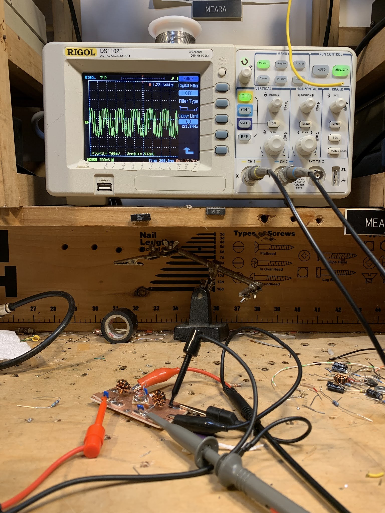
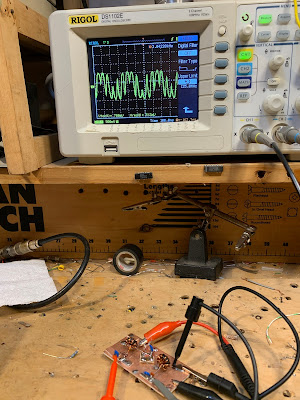
Now that I retired a couple of years ago and am getting out of the VFO kitting business I can finally build complete rigs instead of just making the next-generation VFO’s for everyone else to use. I recently build a tiny, Direct Conversion rig with a Si570 signal generator (of course) and a diode ring mixer (ADE-1). Look at my web page, www.aa0zz.com to see it, along with my VFO projects that I’ve been building in the past. As you well know, Direct Conversion is fun to build and the sound is astounding; however, they are rather a pain to use! Yes, I did make it qualify as a real rig by making several contacts all over the country. (Wes Hayward gave me the criteria: he told me that I must put any new rig on the air and make at least one contact before it qualifies as a real rig.)

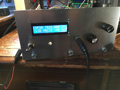
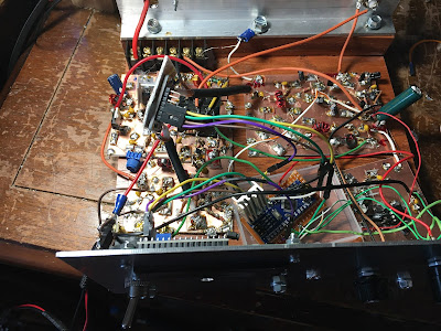
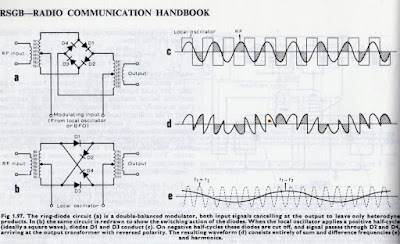
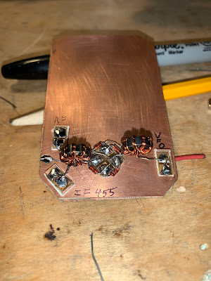
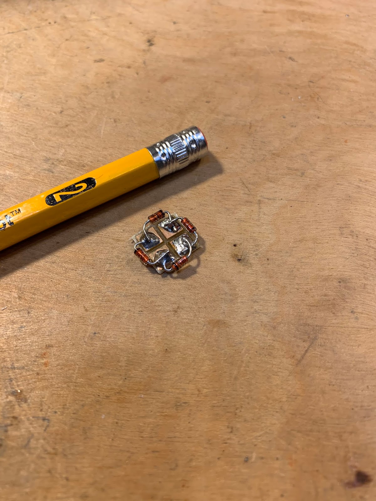
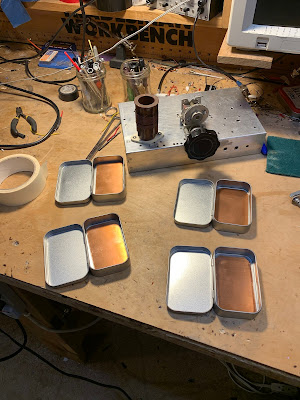
The new rig that’s on my workbench is my own version of a phasing rig, experimenting with a Quadrature Sampling Detector (QSD, sometimes called a “Tayloe” mixer), using some ideas from Rick’s R2 and R2Pro receivers and many innovations of my own. At present my new higher-end Signal Generator works great, the QSD receiver works great (extremely quiet and MDS of -130 dB on 40 meters) and the transmitter is putting out about 16 watts with two RD16HHF1’s in push-pull. You can take away my “QRP-Only-Forever” badge too, not that I’ve ever subscribed to that concept! Still more tweaking to do with the TX but now I’m also working on the “glue” circuitry and the T/R switch. The SigGen, RX and TX are all on separate boards that plug into a base board which has the interconnections between boards and the jacks on the back. I’ve built DOZENS of variations of each of these boards. Fortunately they all fall within the size limit criteria to get them from China at the incredible price of $5 for 10 boards (plus $18 shipping) with about 1 week turnaround. Cost isn’t really an object at this point but it’s more of getting a hardware education that I sadly missed while I concentrated on software for so many years. it’s certainly nice to have willing mentors such as Rick, Wes, Dave (K1SWL), Don (W6JL) and many others to bounce my crazy ideas off. Yes, I’m having a ball!

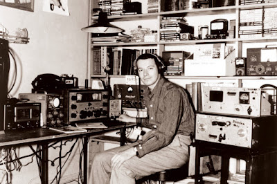
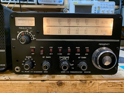
I was licensed in 1964 but out of radio completely from 1975 to 1995. Do you like the picture of my DX-100 on my web page? My buddy in the 60’s had a Drake 2B and I drooled over it but couldn’t afford one.

Now I must finish this rig before you guys send me down another rabbit hole. Too many fascinating things to think about! I literally have a “priority list” on the my computer’s desktop screen. Every time I come up with a new project idea – something I really want to play with such as a Raspberry Pi, SDR, etc, I pull out the priority list and decide where it fits and what I want to slide down to accommodate it. That’s my reality check!

Take care, Bill. Thanks for taking the time to give us many inspiring thoughts and ideas.

73,

-Craig, AA0ZZ

SolderSmoke Podcast #225: Mars, uSDX, G-QRP, HP8640B, DX-390, Rotary Tools, Walla Walla SDR, MAILBAG

SolderSmoke Podcast #225 is available

http://soldersmoke.com/soldersmoke225.mp3

Mars, West Coast smoke.

Pete’s Activities:
— DC receivers.
— CW offset
— GQRP talk
— The uSDX project

Bill’s Bench
— Sliding into the Vintage Test Gear Cult: HP8640B .
— Fixing up and figuring out Radio Shack DX-390 receivers.
— 220 to 110 on a few remaining devices.
— Got myself a Dremel-like rotary device.

Tech News:
— ARRL/TAPR Convention: SDR project from Walla Walla University students. Intuitive explanation for why desired and image freqs in a mixer come out with very useful phase differences.

— Chuck Adams’ Amazing Lab Notebook. Includes a simple circuit to measure resistance and Q in crystals. FB.

MAILBAG:

— Dino KL0S SITSing in his shack, homebrewing 9 MHz filters FB Dino. Airborne!
— Dave NT1U sent us the famous 1968 QST Article by W7ZOI re DC RX.
— Ron K0EIA listening to SWBC staions with uBITX.
— Ted AJ8T Korguntubes making a 12AX7 equivalent.
— Joel N6ALT sent me a nice DX-390 manual. Thanks Joel
— Bob KD8CGH alerted us to the uSDX project — story on the blog.
— Craig AA0ZZ Sent a great message with insights on computer code — I will put up on the blog.
–Tracy KN4FHX reports on optimistic prognosis for SolarCycle 25. Some chickens may have to be sacrificed.
— Stephen M0OMO Thanks SolderSmoke for rekindling interest in this hobby.
— Paul VK3HN has a cool new rig — The Prowler — check it out
— Steve N8NM working on his Sunbeam car — Pete already knew about the carburetor synch problem. N6QW knows everything.


Radio Schenectady

A while back I posted a picture (see below) of the shortwave dial of an old receiver used by my wife’s grandfather. I noted the odd presence of ‘Schenectady” among the exotic foreign locations on the dial. Pete immediately connected the dots by noting that Schenectady was the home of General Electric. This week Chris Waldrup KD4PBJ sent us a great web site describing the shortwave stations in Schenectady. Check out the tube that runs 100 kw AM (Big Bertha).

https://www.radioworld.com/news-and-business/schenectady-shortwave-transmitters-1941

Chris also sent information about BIG AM broadcast band stations:

In addition to Schenectady being home to GE it is the city of license to clear channel AM 50 kW WGY 810. WGY was started by GE so if the radio was GE it was probably a way to promote their station at the time. I heard mention of Rochester too and that would be for 1180 WHAM another 50 kW clear. Both WGY and WHAM are still there going strong banging out their 50 kW.

And Pete reminded us of KDKA, describing its long-lasting impact on one of his ears:


Let us not forget KDKA in Pittsburgh at 1020 which I think is no longer clear channel. I used to listen to KDKA on my crystal set when I went to bed at night. My bed had an exposed bed-spring which was my antenna. To this day there is a slight kink in one of my ears where my Brush headphones rested –I am a side sleeper.

Pete Juliano’s Presentation to the Cedar Valley, Iowa Amateur Radio Club (Slides)

Earlier this month Pete N6QW spoke via Zoom to the Cedar Valley, Iowa Amateur Radio Club. This was an especially appropriate venue for Pete, the creator of the KWM-4; Cedar Rapids was the long-time home of Collins Radio. Many of those in the club used to work for Collins.

Here is Pete’s PowerPoint presentation: http://soldersmoke.com/N6QWslides.pptx

Some notes on the event:


For the Zoom connection, Peter used his Linux Mint computer.
Pete mentioned that Gene Senti, while tinkering in his basement, developed the KWM-1. One of the guys in the audience confirmed Pete’s account, but added something: Collins employees could buy ham gear at a discount. Senti bought a brand new 75A4 receiver (commercial price in late 50s was about $900) and he modified it from being just a receiver into a transceiver. Imagine taking a new radio and doing that! But when he got it working, Art Collins came over to his home to see the invention. The rest is history.
Pete got grilled a bit on why he was still using “analog’ front ends on his several SDR builds — why not Direct Digital Conversion? Pete says he may now try to build a DDC rig.

There was also a lot of very nice feedback on the SS Podcasts – there were many regular listener’s in that group.

You can see Pete’s slides here:

http://soldersmoke.com/N6QWslides.pptx

Lobes, Nulls, and “Gain Dipoles” — Testing the Theory with WSPR

In the last podcast Pete and I were discussing dipole antennas. We mentioned dipoles that were multiples of 1/2 wavelength and said the result could be a “gain dipole.” This provoked some head scratching. Listener Riley asked for more info. See the comments section under this post: http://soldersmoke.blogspot.com/2020/05/soldersmoke-podcast-222-antennas.html.

A short time later Pete was corresponding with Brad WA8WDQ who had questions about his antenna pattern. Pete recommended using WSPR to test his antenna’s effectiveness.

These two exchanges got me thinking about the radiation pattern of my 135 foot doublet antenna, especially on 20 meters. Where are my lobes, where are my nulls? Following Pete’ advice I turned to WSPR. But first, a quick look at the PREDICTED patterns.

ON5AU has on his site a great article by antenna guru L.B. Cebik W4RNL with exactly the info I needed. Above is W4RNL’s chart of predicted radiation pattern for 20 meters on a 135 foot doublet. Note the orientation of the wire.

My antenna is oriented almost exactly north-south (broadsides to the east and west). So with a standard north at top map, my pattern on 20 should look like that of W4RNL’s chart. What did I get from WSPR? Here is the pattern for an hour or so of 250 milliwatt transmissions from my station using the 135 foot doublet on 20 meters (using homebrew balanced tuner):
You can clearly see at least three of the four predicted lobes (NE, NW, SW).

Now, part of this WSPR pattern could, I suppose, be the result of the geographic distribution of WSPR stations. If there are just more of them in the areas where I am seeing lobes, the pattern could just be the result of geographic distribution. I don’t think that is the case, but to test this idea (a bit) I decided to look at the 40 meter pattern.

Here is what W4RNL predicted (same north-south antenna orientation):
And here is the WSPR map that I got, again using about 250 milliwatts for about an hour):
I think this pattern matches nicely with the prediction. You don’t see the nulls that you see in the 20 meter pattern. You do see some stations directly north of me (as predicted). There does not seem to be a big disparity in the geographic distribution of WSPR stations.

One note on the use of WSPR: I started out using WSPR in receive mode, thinking that the pattern I’d see would be similar on receive or transmit due to the antenna reciprocity principle. But I worried that the results could be easily skewed by higher power WSPR stations. So I shifted to the transmit mode and limited my output to 250 milliwatts.

Here is the W4RNL chart showing the patterns for all the bands:
Here is the azimuth chart for my location:

Dilbert, Shep, Dex, Pete, Farhan, and Wes! N2CQR Presentation on Homebrewing to Local Radio Club

Dean KK4DAS asked me to speak to our local radio club, the Vienna Wireless Society. It was a lot of fun. I talked about my evolution as a homebrewer, some of the rigs I made, the moments of joy, and the tales of woe. You can watch the presentation in the video above.

I was really glad to be able to explain in the presentation the importance of people like Pete, Dex, Farhan, Wes, Shep and even Dilbert.

I was also pleased to get into the presentation the N2CQR sign that Peter VK2EMU made for me. Thanks Peter!

Here is the URL to the YouTube video (also above):
https://www.youtube.com/watch?time_continue=3414&v=VHSr-v4QO7Q&feature=emb_logo

And here are the PowerPoint slides I used:
https://viennawireless.net/wp/wp-content/uploads/2020/06/VWS-presentation-Rig-here-is-homebrew.pdf

SolderSmoke Podcast #222 Antennas, Phasing, VFOs, 2-Bs, 6 years of N6QW, MAILBAG

After 46 years, finally a dial skirt
SolderSmoke Podcast #222 is available:

No travelogue but… SolderSmoke Almanac!
Memorial Day in U.S.

End of Ramadan so Eid Mubarak!
#222 marks SIX YEARS of Julian-ismo. He started on SS 161. Thanks Pete.
Thanks to all who sent good wishes on Billy’s graduation. He heads to Boston and the lab in a week or so. Very proud.
——————————————
Bill was on Ham Radio WorkBench Podcast
—————————————–

PETE’S WORKBENCH
— Antenna Ideas — Don’t Buy that $165 dollar dipole! It is just wire!
— THE PHASING RIG. Does this point to a need for meditation? Or at least some temporary disengagement? Tribal wisdom from Pete.
— DEAN KK4DAS’s rig. The Furlough 40. Troubleshoot. Tribal knowledge.
——————————————-
— SHAMELESS COMMERCE DIVISION: AMAZON BOX — SEARCH FOR ANYTHING OU WANT THERE.
— PLEASE PUT COMMENTS ON THE SOLDERSMOKE BLOG POSTS.
PLEASE CHECK OUT THE SolderSmoke YOUTUBE VIDEOS.
——————————————

BILL’s WORKBENCH
n Shortwave dials and exotic locations. Java!
n Galaxy V VFO Project. Series-tuned Colpitts.
n DRAKE 2-B. Hayseed Recap. Put the skirt back on the old rig. Reduction drives?
SHOPPING BAG:
I got a replacement for the Xtronics 4000 soldering station. Yaogong worked!
Ordered screws and stuff from McMaster — Came very fast!
Working on a resistor kit from Mouser.
MAILBAG:
VK2BLQ’s Phasing RX with an HRO dial. Cool Retro.
Adam N0ZIB — Cool station. TFT screen Aluminum welded box. FB.
Karl G7AFT BITX 40 doing USB and LSB by changing the VFO freq. Pete’s trick!
Jerry KI4IO out in nearby Warrenton. Hope to be able to meet up soon.
Keith N6ORS’s Hot Mustard Phasing Board.
Mike N5GTF’d FULLY INDOOR Quarantine Receiver. Need a slogan for the antenna!
Nick M0NTV’s Bread Bin 80 Quarantine rig
Bruce KC1FSZ Quarantine 10 — Brave man in solar minimum. But I hear 10 is opening.
Talking to Grayson Evans KJ7UM TA2ZGE about Collins 9.9 MHz transformers.
Talking to Alan Wolke W2AEW about Drake 2-B stuff Was there a reduction drive?
Paul VK3HN about Ceramic filter spurs.

Peter VK2EMU notes no animals were harmed in the making of my videos. But many electrons were agitated.

N6QW Phase Shift Success — It aint over ’till the fat lady sings


Video on the Galaxy V VFO Project

This is the second version of this video. I had some technical difficulties getting it to upload in High Definition, but I was able to work it out in this version.

In this video I describe the VFO project, talk about how I made use of the e-bay Galaxy V parts, talk about the circuit (series-tuned Colpitts), conduct some stability tests, and discuss many of the ways a VFO like this one can be useful to the radio amateur.

Thanks to Pete Juliano for inspiring this effort.


QSO Today — Episode 300 — Panel Discussion

Congratulations to Eric Guth, 4Z1UG for reaching episode #300 on his QSO Today podcast. To commemorate the event, Eric organized a panel discussion. It was a real pleasure and honor to participate.


Thanks again Eric!

Dean KK4DAS Builds SSB rig, Makes First Contact.

You can almost see the excitement in the notes (al fresco!) of Dean KK4DAS. He made his first QSO with a homebrew transceiver this week. Not long ago Dean was taking his first tentative homebrew steps with a Michigan Mighty Mite. Wow, he has made great progress.

Congratulations Dean!

Videos on the Q-31 Quarantine AM SW Receiver Project (and some pictures)

I’ve been making some short, stage-by-stage videos of my Q-31 receiver project. So far I have seven videos. They are here:

https://www.youtube.com/user/M0HBR/videos

Please subscribe to my YouTube Channel. And give me some “thumbs up” if you like the videos.

Thanks. SITS! FlattenTheCurve! 73

Pads from Pete, toroids from Farhan
The diode ring
Altoids-sized tins will hold the circuit boards
Stay In The Shack — Or in the front yard.


Quarantine Reading: Tribal Knowledge: Two Gems from Pete Juliano N6QW

WB9FLW recently reminded us of two very useful documents that have been kind of buried on one of Pete’s web sites. I think these documents are just the kind of thing we all need during these dark days of quarantine. So just sit back, StayInTheShack, and soak up tribal wisdom from the Wizard of Newbury Park.


Here is the message from WB9FLW that unearthed these gems:

Morning Pete,

Three cheers for posting the Simple SSB Transceiver as a possible project during the pandemic lockdown.

Suggestion, folks that are new to your Website may not have seen some of your earlier posts especially on jesssystems.com.

“Homebrewing For QRP SSB” is a gem and a great lead in to the simple SSB Transceiver project.


There is a lot of wisdom in those pages, perhaps you can add a link for those interested in building the rig.

“How To Stuff A Junk Box” is good as well.


Hope you and the family are doing well.

Pete WB9FLW