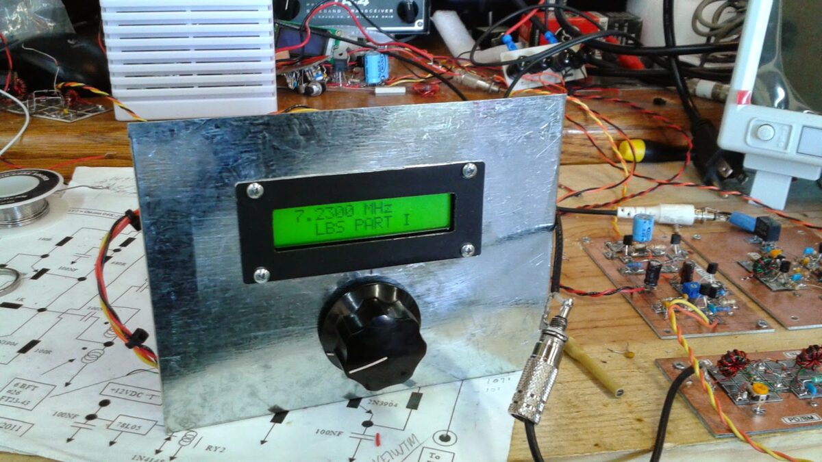
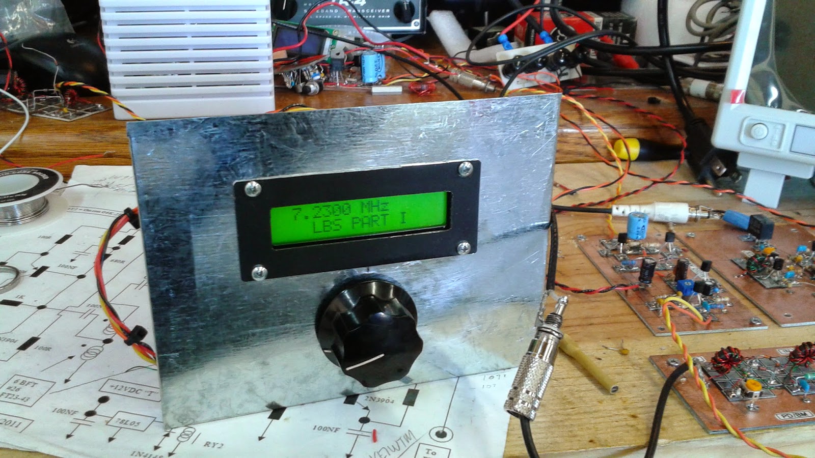
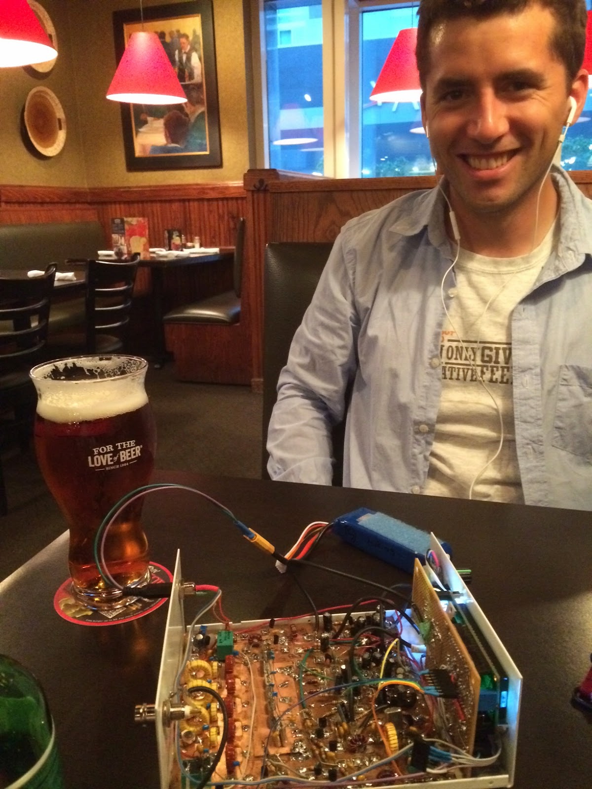
Pete and I congratulated Colin on the First Sigs heard by his BITX (sort of like First Light for a telescope.) He is clearly following the advice offered by Farhan in the original BITX20 article: Take a break when the receiver is done; sit back to enjoy the sounds of success. I told Colin that having a small error in the build, then finding it and fixing it, well, that’s icing on the cake OM. This also shows the benefit of having an oscilloscope. Here is Colin’s report:
Hi Pete and Bill,
I really enjoyed the latest SolderSmoke! I think you two have got a winning formula, humour interspersed with valuable technical knowledge. Some podcasts are just too serious, there’s nothing wrong with having fun in your hobby!
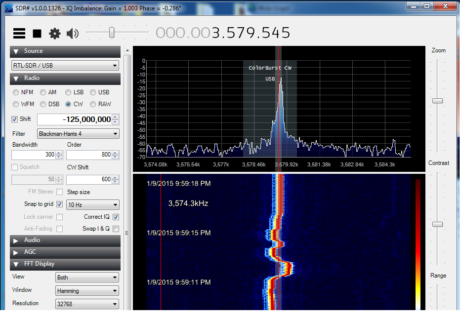
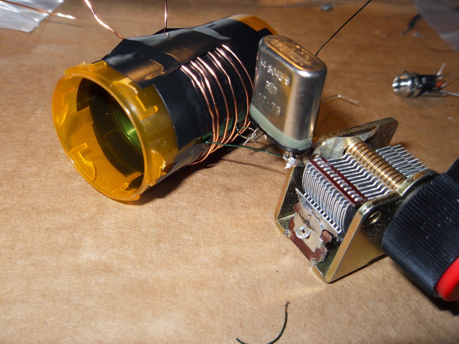
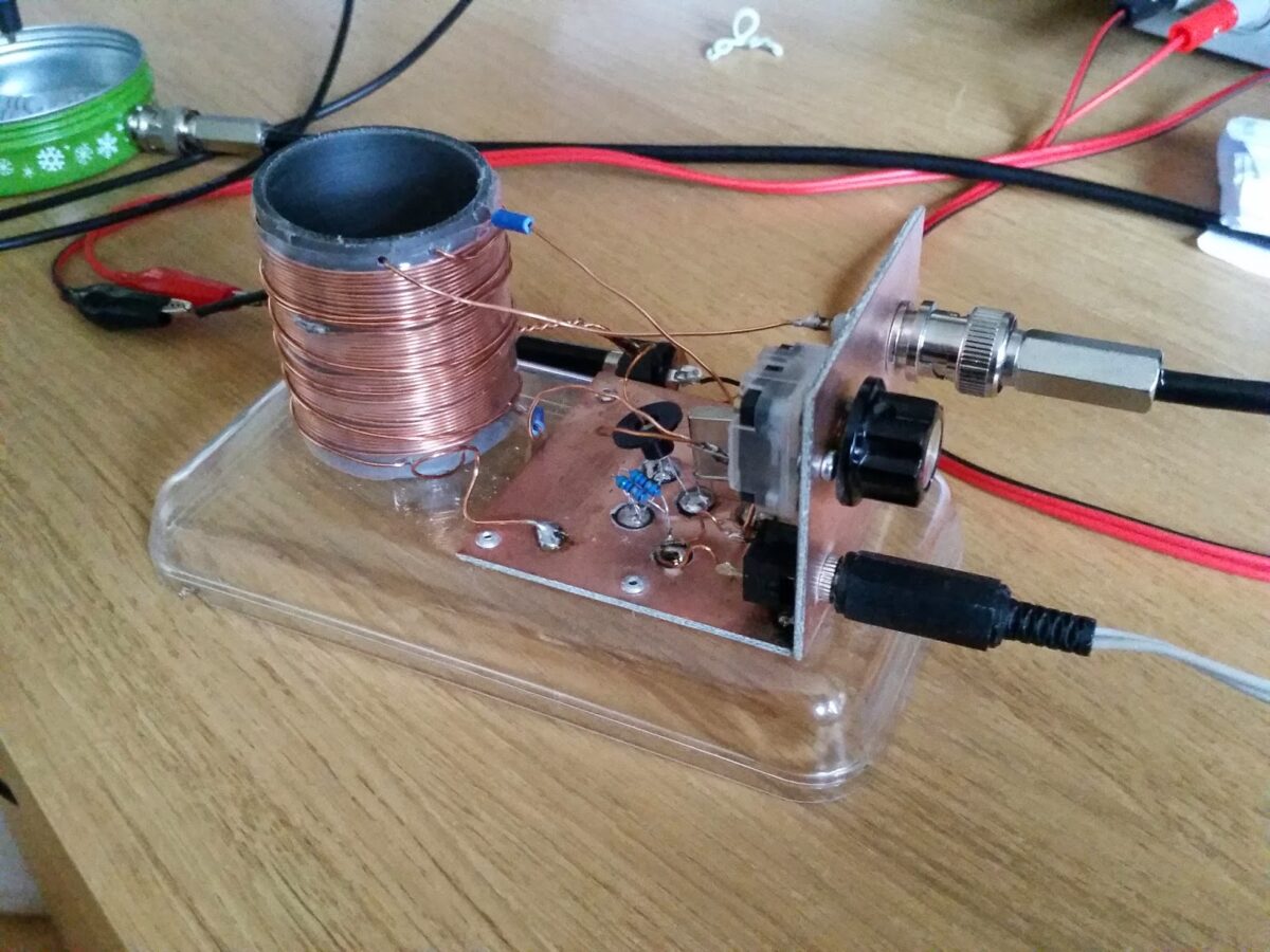
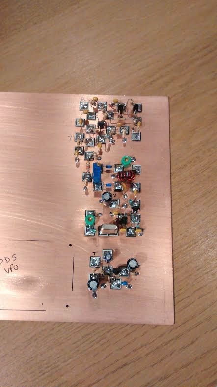
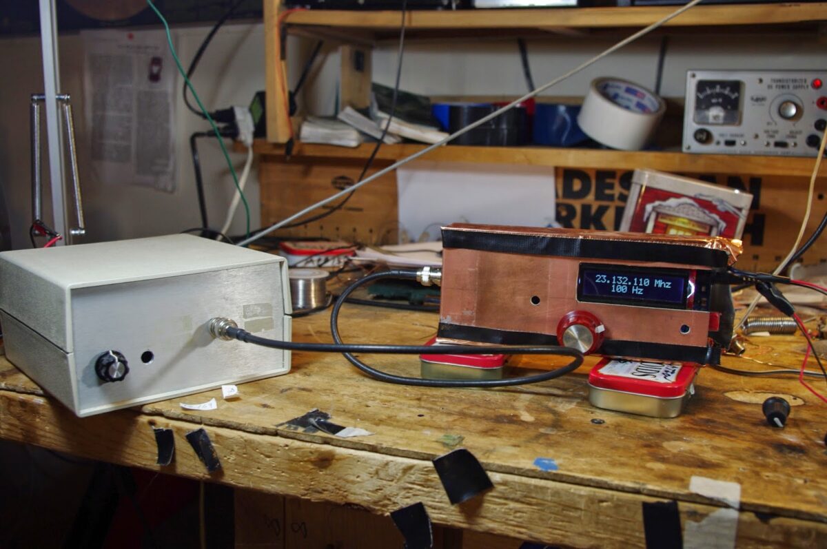
Progress is slow here, as always, but each week I have managed to move a little bit further forward. This week I aligned my BITX band pass filter and made a rough measurement of my crystal filter using the DDS signal generator that I built last week.
My oscilloscope is a Tektronix 465, older than me I believe! Of course there is no fancy signal level readout like the modern digital scopes, so I had to just peak the injected signal through the crystal filter and measure the frequency using a frequency counter connected to the IF amp. I followed the BITX ver 3 build instructions and my results seemed to match very closely to the Indian kit. I’m going to set my BFO at the -20dB from peak level as suggested in the ver3 instructions, I guess I can fine tune the setting later.
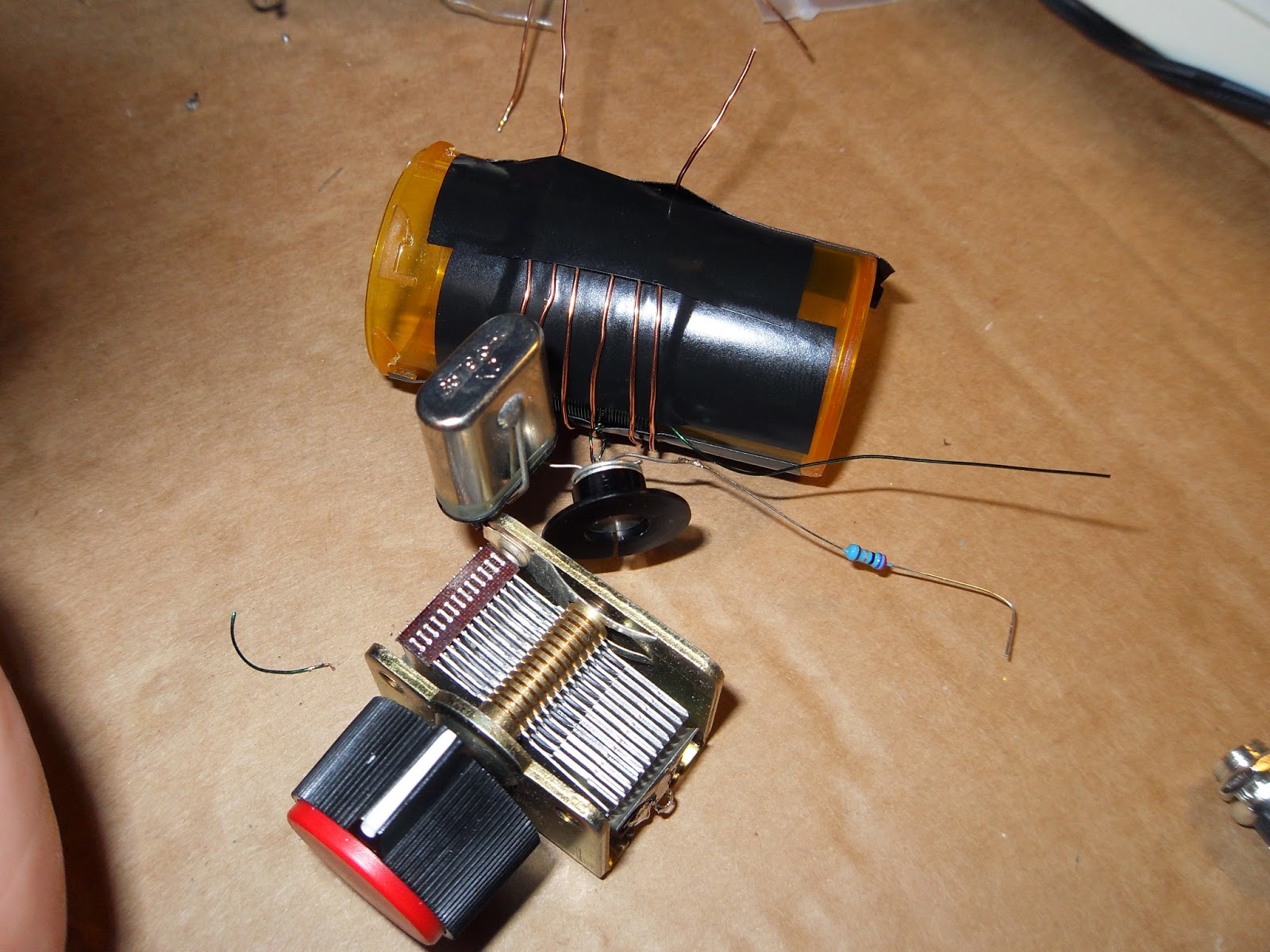
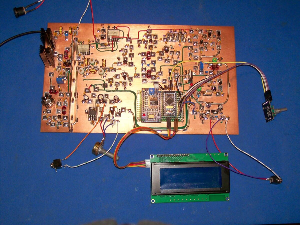
At first I had no signal making it out of the last RX IF amp, I traced the signal right through to the base of the first transistor but then the signal was lost. I had thought that band conditions were poor when I tried my BITX in RX last week when in fact it turns out that I’d made a small mistake building the IF amplifier that follows the crystal filter! I had wired the 4k7 resistor in the wrong place! I made the circuit good and hey presto, lots of signal coming out of the amp!
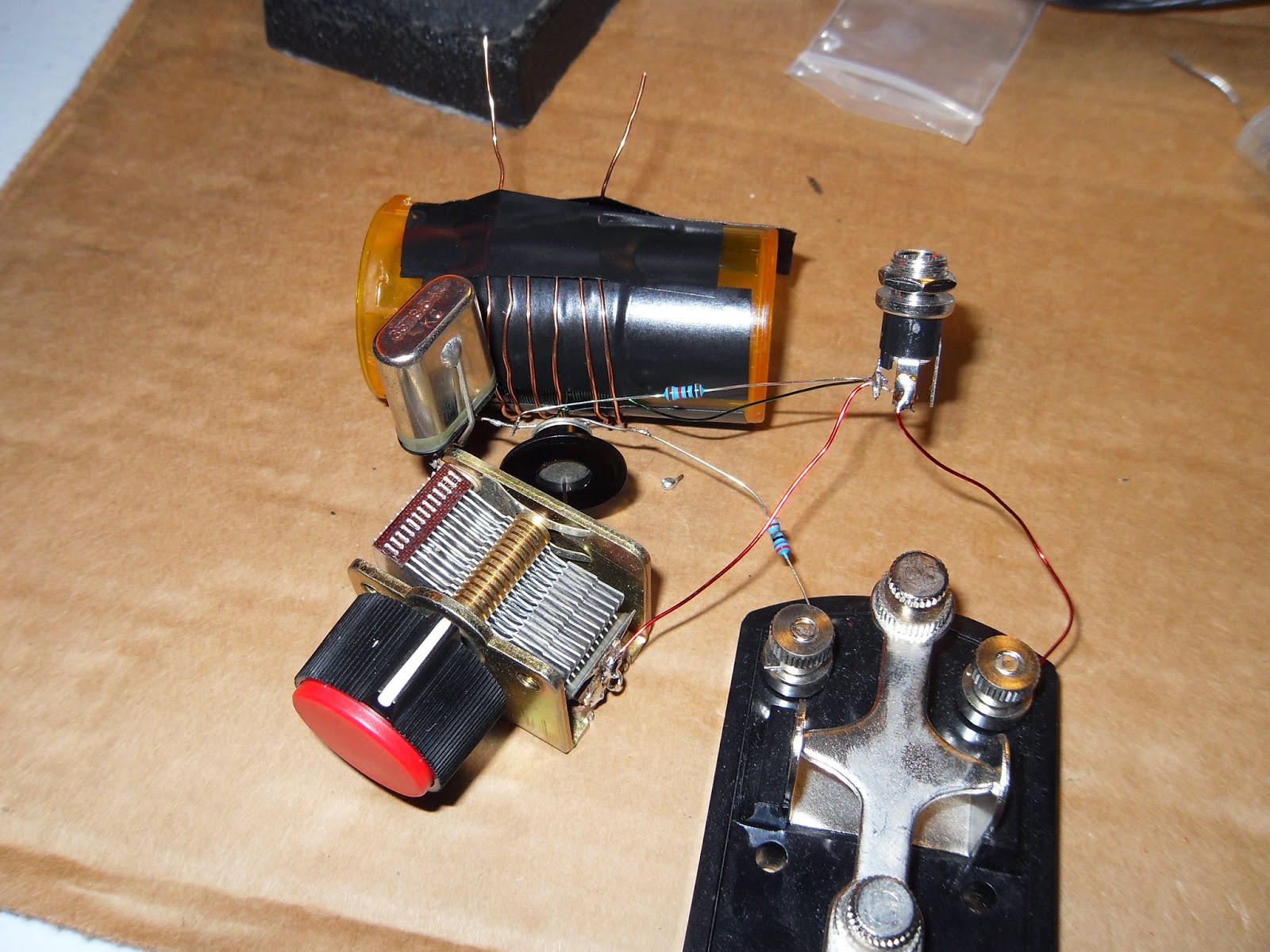
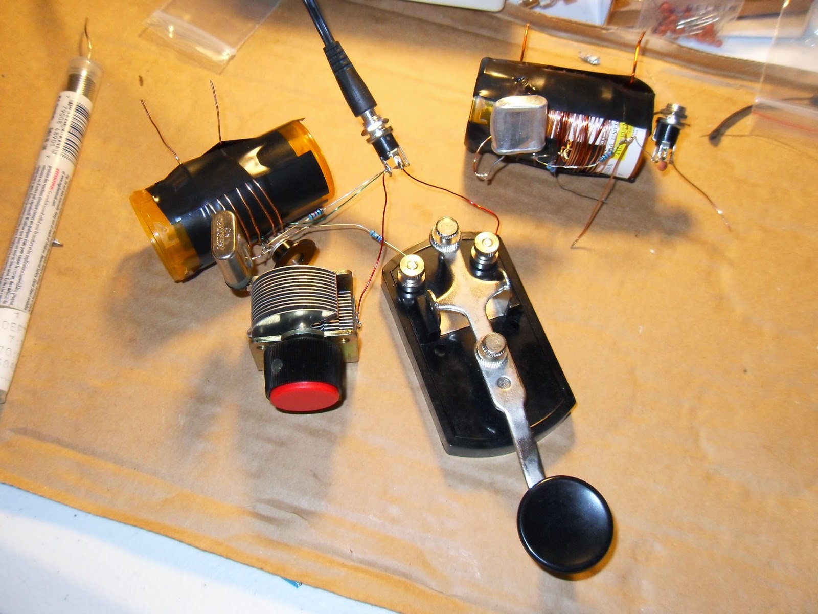
I was eager to give the receiver another try. On Fridays work finishes at 1pm, so a great chance to try out my rig during daylight hours. I hooked up the rig to a random piece of wire and I was amazed by the great noises coming from the speaker! I hadn’t even set the BFO but voices were just leaping out. Man that rig has a lot of AF gain! I obtained a switched 10k log pot which I intend to use for power on and AF gain so hopefully the volume control will be OK. As a side note, it was nice to hear HF0YOTA down in the CW portion, I’m guessing that it is youngsters on the air station, I must do a search on the call later.
73, Colin M1BUU
So the little signal generator has already earned it’s keep. I guess I can would have been scratching my head for a while without it!
Our book: “SolderSmoke — Global Adventures in Wireless Electronics” http://soldersmoke.com/book.htm Our coffee mugs, T-Shirts, bumper stickers: http://www.cafepress.com/SolderSmoke Our Book Store: http://astore.amazon.com/contracross-20


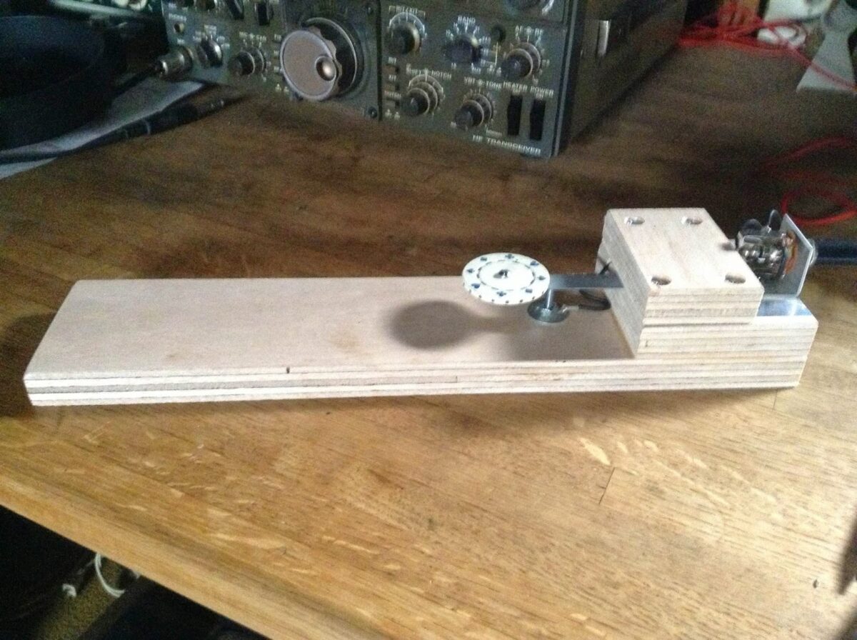

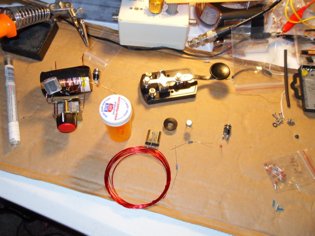
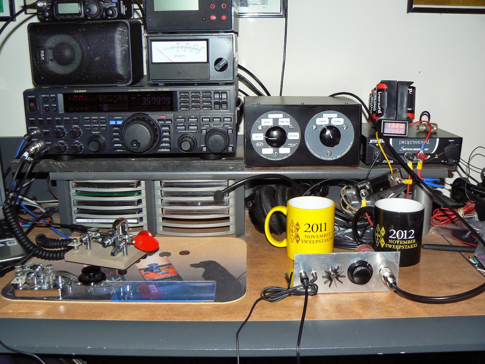
 . Your right about the homebrew key being a hacksaw blade and a few pieces of plywood. The knob is an old poker chip. You can adjust the spring tention by moving the blade in and out of the plywood. Travel can be adjusted by raising and lowering the bolt under the blade. I needed something for CW and wanted to stick to the ham maker thing. As for me sending lefty, I do that so I can switch when the right gets tired or I need to hold ipod for video. Thanks for what you add to soldersmoke. 73.