
Santa managed to include in his delivery some of the materials that I needed to build my 160 meter inverted L antenna. You see, Steve Silverman, Pete Juliano and I have collectively more than 150 years in ham radio, but none of us have ever operated on Top Band. The three of us have taken A SOLEMN OATH to correct this horrendous deficiency. I am in the vanguard, partly due to a weather pattern that is perfect for antenna building.
Armed with a new elastic band for my Wrist-Rocket sling shot and some perfectly shaped lead sinkers, yesterday — with the obvious cooperation of The Radio Gods — I managed to get two ropes over some 70 foot trees. Soon — with minimal gnashing of teeth — I had 185 feet of wire in the air.
This morning I was messing around with L networks at the base of the antenna. I took a coffee break, leaving the 185 foot wire and the ground system connected to the coax. I had the transmitter off, so I was surprised to see the SWR meter jumping around a bit, up significantly from zero. What could that be? It wasn’t coming from my station, so it had to be coming from some other transmitter. And the slight bit of jumping that I saw on the SWR meter had the familiar pattern of the human voice. Some radio sleuthing ensued.
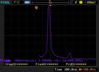
I flipped the station antenna switch to the “bench” position, and connected my scope to the coax. Wow! I immediately saw a big strong AM signal with modulation, at about 5 or 6 volts peak to peak. The Rigol ‘scope gave the frequency: 1220 kHz.
I tuned the HQ-100 to that frequency. As I listened to Gospel broadcast, I could follow the voice peaks on the ‘scope.
Some Googling ID’s the station: WFAX 1220 AM. 5 kilowatts in the daytime. 1.5 miles from my house. The vertical portion of the inverted L is obviously picking up a LOT of energy from the WFAX tower. And the horizontal portion of my antenna is broadside to the WFAX tower.
Of course this all made me think about throwing together a crystal radio, but then I realized I’d already listened to WFAX with simple diode — the one in my SWR meter. That little SWR meter was acting like a crystal radio with a visual output!
Category: Juliano — Pete
SolderSmoke Podcast #183 Pete’s B’day, Simple-Ceivers, Binaural Bliss, 160 or Bust, GOOD BEHAVIOR, MAILBAG

Bill’s Frankenstein R2 receives 7 MHz signal and generates I and Q outputs
SolderSmoke Podcast #183 is available. And it is GOOD!
http://soldersmoke.com/soldersmoke183.mp3
20 December 2015
— Foxes in the Backyard
— Pete completes another orbit
— Simple-ceiver Success!
— Frankenstein Receiver: IT IS ALIVE! AND BINAURAL!!!
— 160 Meter AM OR BUST!
— Fun on 40 AM — Lots of Multi Elmac AF-67s! Who knew!
— The Amateur’s Code, and violations thereof.
— Negative Frequencies? I don’t think so.
— Capacitor Offer from our Secret Benefactor: EXPANDED ELIGIBILITY
— Projects for 2016: Pete goes Raspberry Pi, Bill goes DX-100
Mailbag:
— Croation Creation
— Salvadoran 2B
— N3FJZ’s Homebrew QSL
— WA7HRG’s LBS-ZIA-Simple-Ceiver Mashup Rig
— KC0IZR turning VCRs into Mighty Mites in NOVA
— AB1YK Starting with DC RX, going BITX
— G8GNR puts Mighty Mite on AM!
— G3ZPF Modulates THE SUN (Amazing)
— VK3YE’s Simple Superhet
— Grayson in Turkey drools over KG7TR’s Octalmania
— N7REP reaches for the Zantac because of Arduinos and Surface Mount
Mama Mia! Mikele’s Croation Simple-ceiver Video
You can just feel the homebrew enthusiasm in this video. You can almost smell the solder smoke.
We love it when people do videos showing their new rigs spread out on the workbench with individual boards held together by bits of solder. It is even better when, as in this video, the boards are atop hand-drawn schematic and parts-placement diagrams with much NOODLING in evidence.
FB Mikele! And I agree with you about the stations who call “CQ DX-only.” I used to hear that a lot when I was in Europe, and I hear it hear quite a bit too. I always think it is a contradiction in terms. There were times when I was sitting there with a new rig, anxious to get a signal report from a strong station, and he wouldn’t come back to me because of the Continent that I was sitting in! Pity. His loss. He might have been interested to hear about the contraption I was testing. It could have been fun, but no, he preferred to work VK3 or Puerto Rico for the 1000th time.
Indeed, three cheers for the legendary Pete Juliano!
WA7HRG’s LBS-ZIA-Simple-Ceiver Project
Wow Pete!
Thanks for the GREAT info. Can’t wait to try things out. One day soon (Christmas is coming) I will have a new computer and can start learning LTSpice.
Great tribal knowledge on the over all gain adjustments as well. And I won’t tell the illuminati .
.
As for your articles, blogs, tribal knowledge and pot casts with Bill. Love them. Listen and read everyone. Print and file for later. Mostly because I can’t keep up with you on all the great projects.
But in the sprit of home brew and not just stuffing boards or following explicit directions I have built the LBS with my own mods.
1. It’s dual band. Almost. 40&20 LPF and BPF already in. 5watt tx works great but plan on putting in about 40 watts them getting around to making the dual band changes to the sketch and finishing things. I used my own audio amp design. Well not all mine. Manufacture spec sheet and Internet info and LBS. Your preamp, a NTE1288 10 watt audio IC.
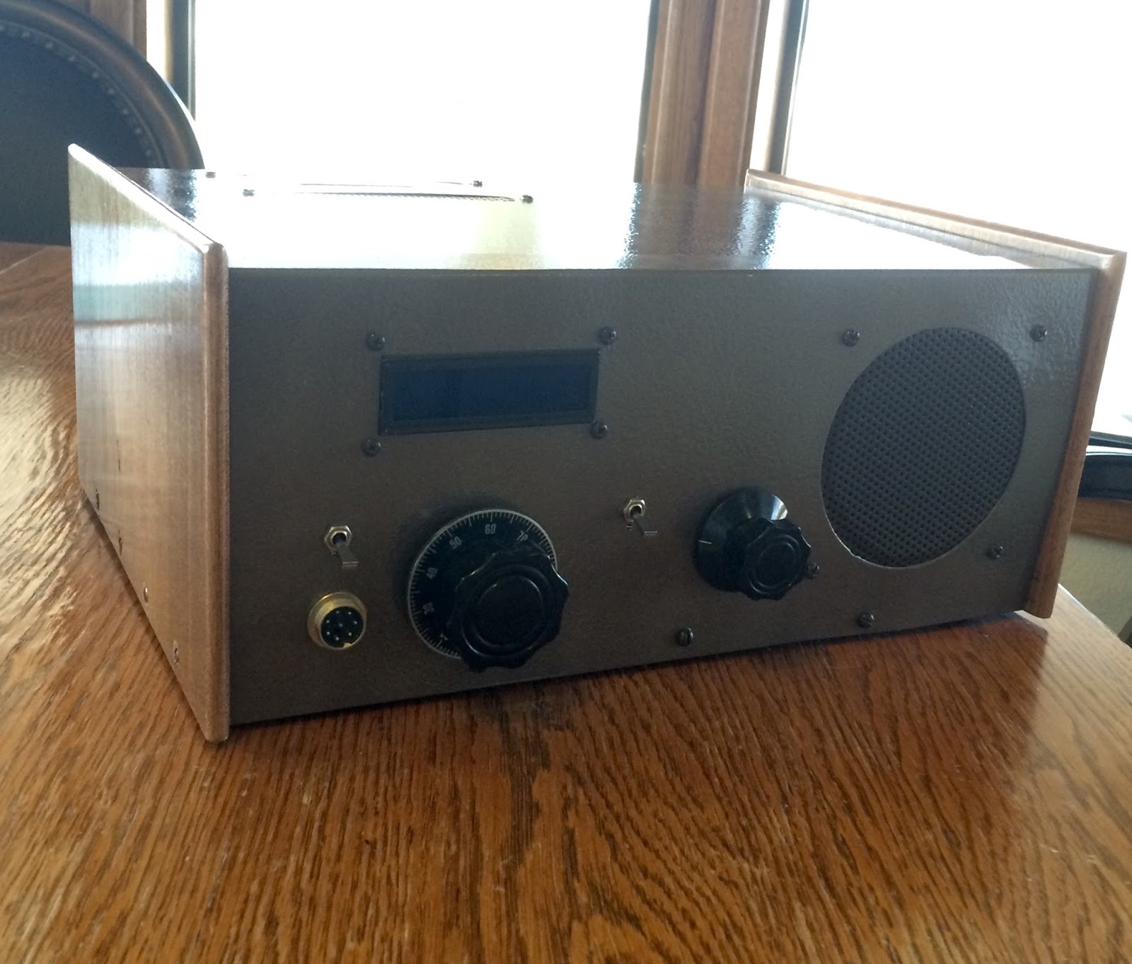
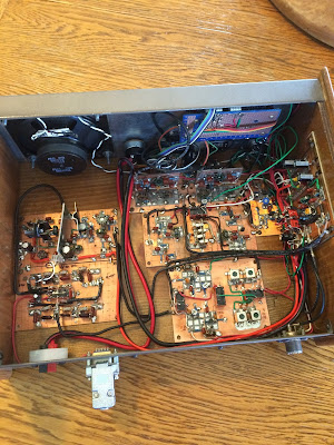
Attached are pix of the LBS so far.
The current rig will be 20 meters only for digital modes. It will have a built in audio interface and thinking about including raspberry pi and TFT screen. But that’s got to be down the road.
It’s a hybrid again. Parts of LBS and ZIA and parts of Simpleceiver. I already had the ZIA IFs built so will have to try the dual FET on the next rig. Modified the audio again. Put in an FET AGC between the preamp and the final IC. About 40 dB dynamic range so should cut down on the vol control twisting when listening to a QSO with one strong and one weak station. So far this build consists of a box of tested modules that have not been hooked together yet. Your FET RF amp will the next board.
Also working on an Arduino Lightning detector with 5115 display. Almost got that one…. Have built couple prices of test equipment. A xtal osc with onboard freq counter and an LCR Transistor tester.
Oh and lets not forget the MMM on 3.58!
I personally know one other ham building a LBS. So don’t think your talking into outer space. We are out here listening! And learning! And having a great time.
And yes, when I catch up on projects, I’m going to build the actual Simpleceiver.
Thanks again for the fast response. I’ll let you know how it turns out.
Jim
WA7HRG
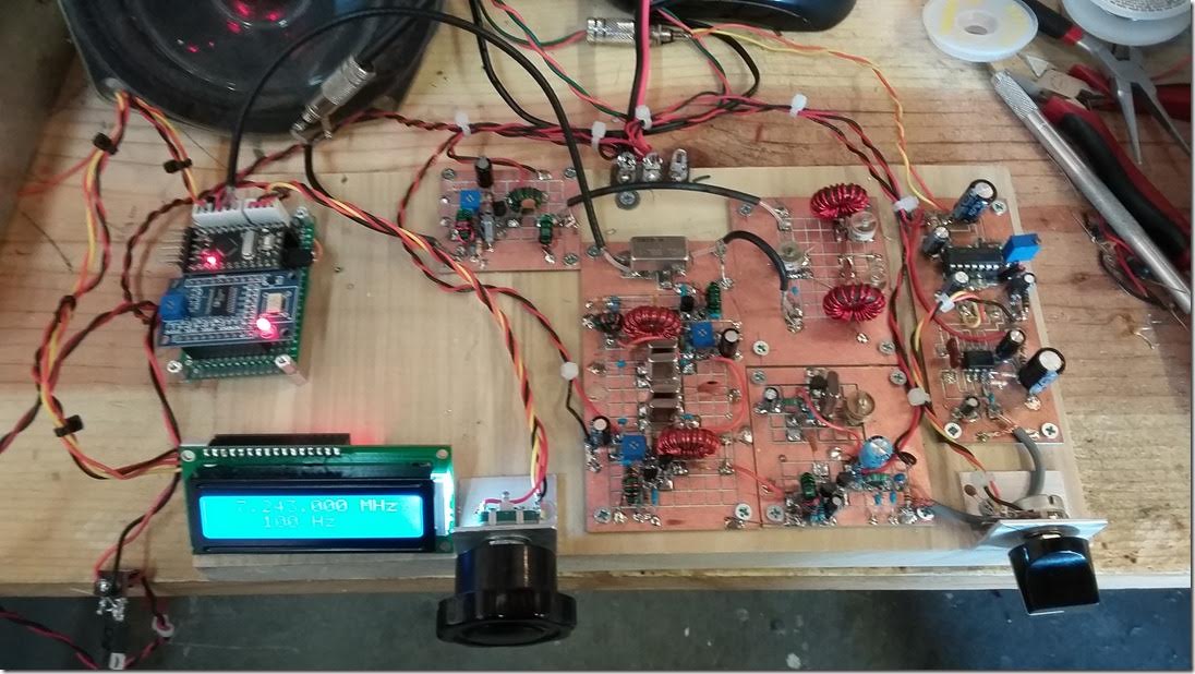
New Rig: The FRANKENSTEIN Phasing Receiver

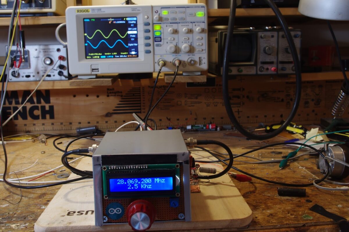
Here is my latest project. I call it The Frankenstein because of the two BNC connectors that come off the side of the DDS oscillator box — they look to me like the bolts on Frankenstein’s neck. The square waves from the DDS LO also seemed to evoke Frank’s bolts. There may be other similarities. We’ll see.
Here is the idea: Phasing, Direct Conversion, Image Rejecting receiver based largely on the R2 design by Rick Campbell KK7B as presented in the January 1993 QST.
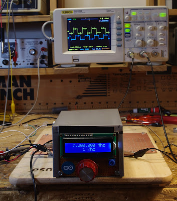
I’m using an AD9850 with an M0XPD Kanga board and an Arduino to generate the quadrature LO signals (you can see the square waves on the ‘scope in the background). I’m using the software of Richard AD7C; this, combined with the divide-by-4 scheme on the Kanga board, puts the upper limit of reception at 7.3 MHz. That’s OK for now.
When I first fired up my AD9850 box I was dismayed to find that the square wave quadrature output was no longer there. I was about to give up and get anther shield board, but this kind of surrender bothered me. So I started troubleshooting and isolated the problem to the /4 chips. My soldering of the surface mount chips was, well, a bit dodgy, so I changed to a tiny soldering tip and reheated all those tiny little pads. Hooray! I fixed it.
The receiver will be built mostly on a PC board that Pete made for me back when he was trying to convince me to build a fourth BITX receiver. I am pleased to put the board to use. See below.
Yesterday I soldered on the two SBL-1 mixers that will form the heart of this receiver. I realized that the very robust quadrature square waves from the Kanga board might be robust enough to fry the sensitive little SBL-1s. Sure enough, I measured about 17 dbm coming out of the Kanga board. I threw together two roughly 10 db resistive pads. These should prevent the SBL-1s from releasing their smoke.
I hope this receiver will be four receivers in one:
1) Standard DC receiver.
2) Binaural Receiver! Groovy, stereo CW that floats around in your head, man!
3) I-Q receiver that can be fed into the sound card of the computer for DSP, panoramic display, etc. I promise not use it to find fault with the signals of homebrew SSB rigs.
4) SSB image rejecting receiver for easy, Direct Conversion SSB listening without the burden of having to listen to the other side of zero beat.
There is already a lot of soul in this new machine: Kanga board with the design my Paul M0XPD, PC board made on Pete’s $250,000 CNC machine, and all of it on an actual breadboard (from Italy, I think).
Rick Campbell and Peter Parker have commented on the allure of phasing rigs. There is something very attractive about them. There is a cleverness in the way this design exploits the phase relationships between sidebands to allow us to null out the unwanted side of zero beat. It took me a while to really understand how this is done — once I understood it, I really wanted to build a rig that would make use of this principle.


Pete Juliano’s Simple-Ceiver on Hack-A-Day Today!

Check it out! Pete’s awesome project — and equally awesome documentation of the project — is recognized this morning by Hack-A-Day! Congrats Pete!
http://hackaday.com/2015/12/03/radio-receiver-build-log-and-more/
Pete’s Simpleceiver is DONE! And it is a thing of beauty
Pete’s Simpleceiver is a thing of beauty. And it is done. And people are already building it: Jim WA7HRG has one in the works. Go to Pete’s blog for more details, pictures, videos, LTSpice simulations etc. http://n6qw.blogspot.com/ Congrats Pete!
Pete’s Suggestion for My Next Rig
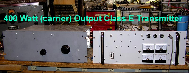
OR THIS:
The Class E rig is very tempting. But no way on the ebay! Too much of an appliance — it even looks like a refrigerator.
AM Madness: Just When You Thought It Couldn’t Get any Cooler…

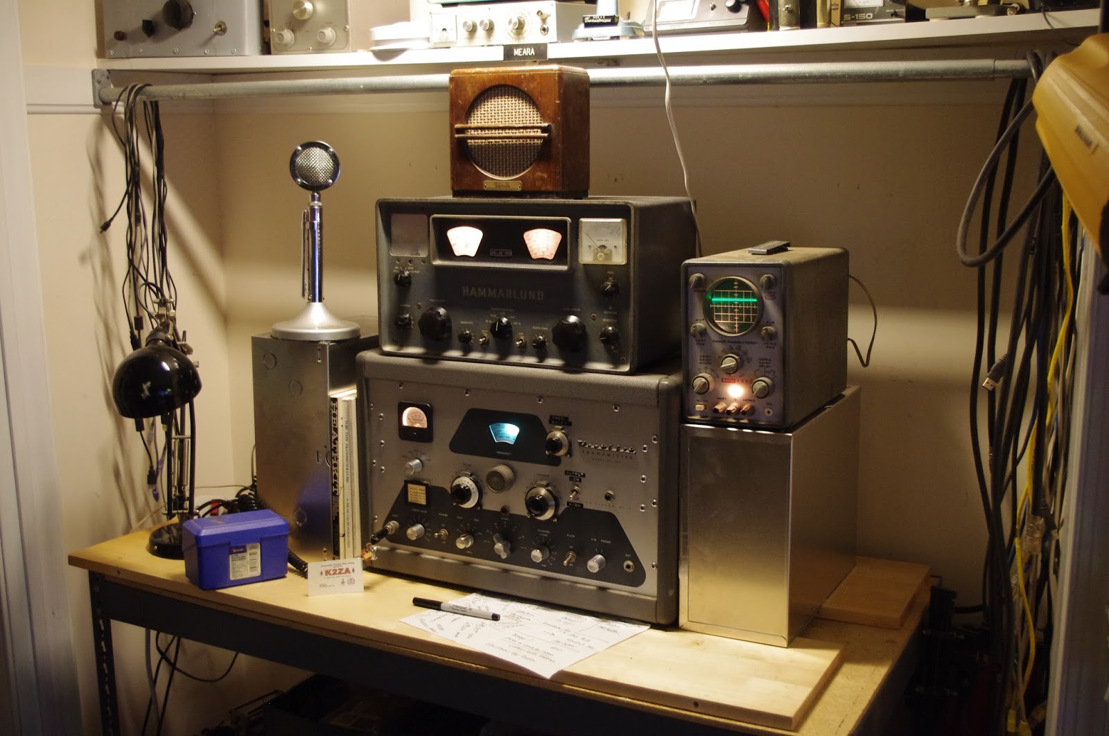
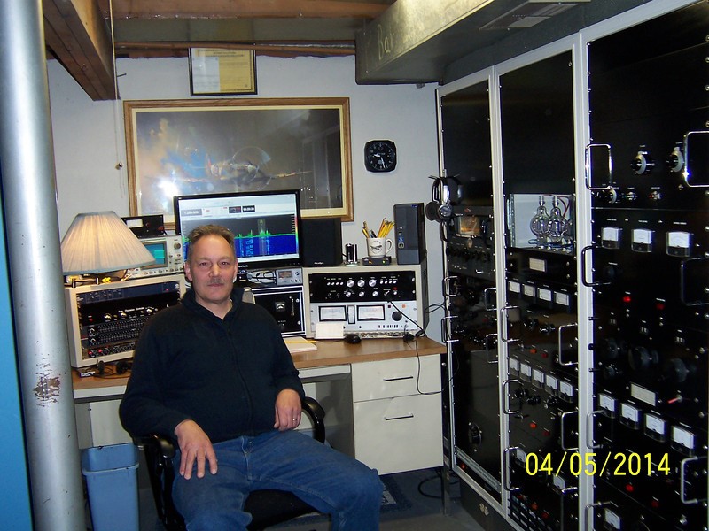
I pulled an old Eico 435 ‘scope out of retirement. I hope to use it as a modulation monitor (any suggestions on easy ways to hook it up for this purpose?). I really like the grey and aluminum look of this station. I tried putting a DX-60 on the same bench, but the green of the “modern” Heathkit clashed with the serious-radio look of the DX-100 and HQ-100. Thanks again to Tim Sutton for the aluminum boxes — I am temporarily using them as supports for the D-104 and the ‘scope. You see, I’m standing up when I modulate this gear. Somehow it seems right. Also, the transmissions on AM are so long that you can go back to your chair and rest (a lot!) between your transmissions. When your turn comes, the few seconds it takes you to get to the rig provide the customary (and polite) “dragging of the feet” that allows others on the frequency to announce their presence. Then comes what is perhaps the most fun part of this setup: the AWESOME KERCHUNK sound of the DX-100 going from receive to transmit. As you can see, we pay a lot of attention to aesthetics and radio ergonomics here at SolderSmoke HQ. That little blue recipe box holds my AM contact card file from the 1996-2000 period of operations from Northern Virginia.
I’m planning on doing a little work on the DX-100. There is a standard set of mods to the audio amplifiers, mostly just changing some caps. And I need to find out why some of the crystals are not working — I suspect dirty contacts. I might also change the mic connector. Looking ahead, Steve Silverman KB3SII (SolderSmoke Lex-pert), Pete Juliano N6QW and I have vague plans for an assault on 160 meter AM.
Over the weekend this rig yielded a number of really FB contacts. Brett N2DTS in South Jersey was running an amazing homebrew station:
CB to 10 Conversion? The Radio Gods Seem Ambivilent
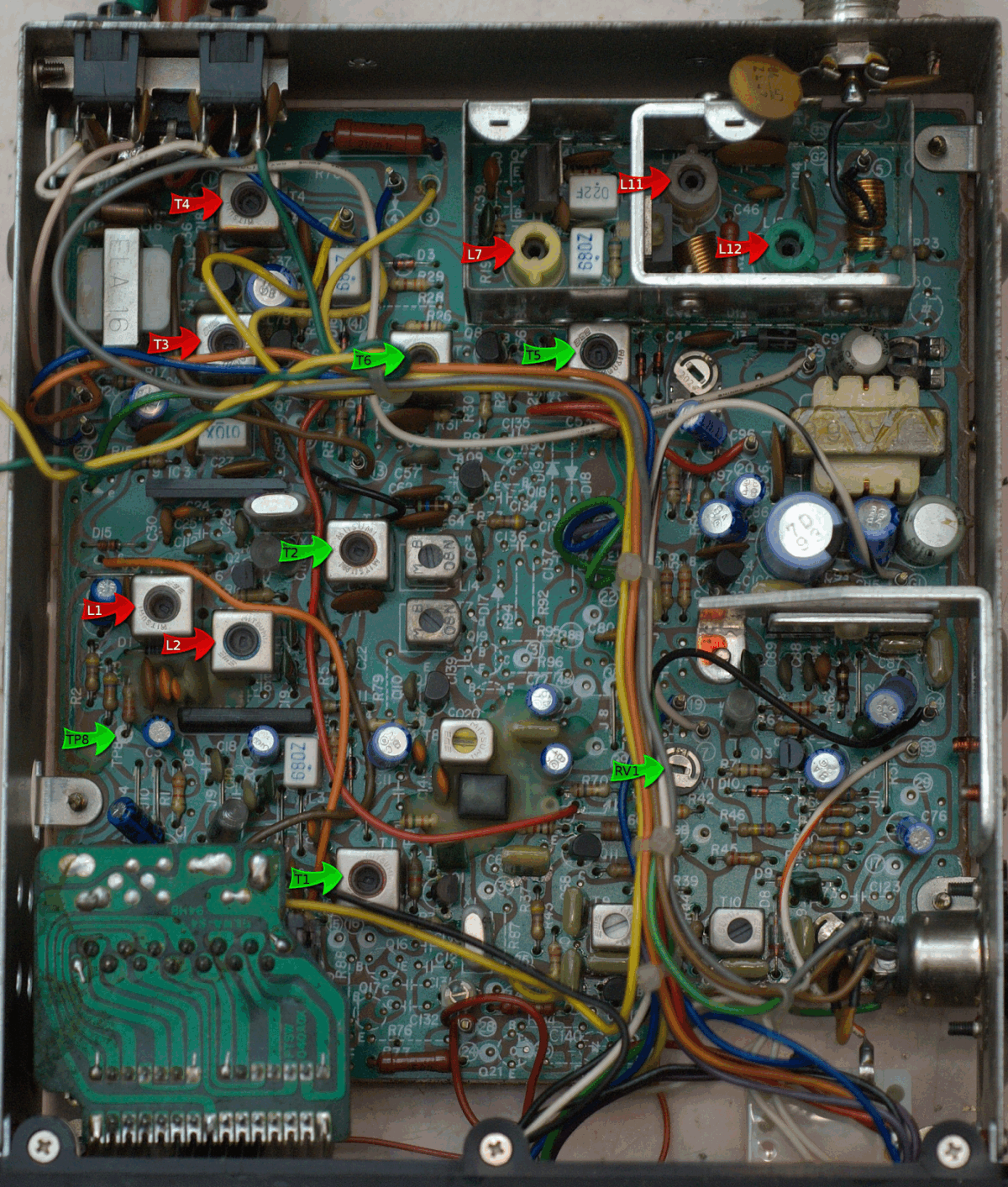
A lot of trouble can begin with a 5 dollar purchase, as I found out after I bought a nickel bag of CB at a hamfest.
The embarrassing little Good Buddy appliance has been hidden away in my junkbox for a while. I pulled it out after watching Pete’s videos about the conversion of his Ten-Tec Model 150A commercial rig. I thought perhaps I could use a little DDS or PLL board to bring that CB rig onto 10 or maybe even 12 meters.
The first thing I noticed when I opened it up was the smell — there was a very strong chemical electronic smell. It was as if components and wires and adhesives and PC boards had been venting inside that case for several decades. This wasn’t that pleasant electronics smell that you get from a Drake 2B or a DX-100. No, this was different. It gave me a bit of headache. That’s a bad sign. I began to wonder if the Radio Gods might be sending me a message.
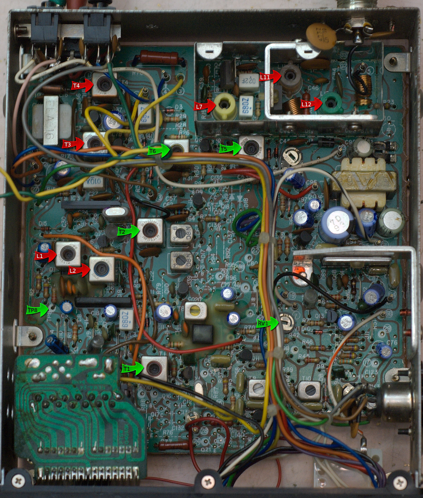
But then I found this very cool conversion site:
http://www.jcoffman.net/WB5RUA/10_meter_AM_conversion_w_Photos.html
Wow, a few snips, a few jumper wires on the PLL board, and a few coil tweaks and that thing would be on 10 meter AM. I also learned that the “Cybernet” board that was stinking up my shack was VERY common in CB rigs, so there is a lot of info about it on the internet. This thing seemed to be crying out for a quick and easy conversion to ham-dom.
So I don’t know which way to go with this one. I’m getting contradictory signals from the Radio Gods. What do you guys think? Garbage can or workbench?
Homebrew Computers — REALLY Homebrew Computers
Hackaday has an article today that is, for me, very timely. In our last podcast, Pete and I were discussing the meaning of the word “homebrew” in the world of Software Defined Radio. As always, Pete was closer to the cutting edge, while I remain mired in Ludite (one D please!) curmudgeonism, committed to RADICAL FUNDAMENTALIST HOMEBREWING. No chips and no menus for me please.
Today, the Hackaday guys came to my rescue with a blast from the past. Homebrew computers! Not that simple “buy a mo-bo and plug in some boards” stuff. No, REAL homebrew, so HB that they even made their own components. 1968. I can dig it! I should have gone down this road. I had the C.L. Stong book “The Amateur Scientist” IN MY HANDS. It had some great articles about relay-based computers. I could have been rich!
HB2HB! N3FJZ-N2CQR Si5351 and BITX TIAs on Both Sides, with Some LBS and Peter Parker Circuitry Too!
In those dark days of February 2015, when all the members of the SDR ESSB Panoramic Spectral Police were on my case over some imperfections in my 40 meter homebrew SSB signal, Rick, N3FJZ came to my rescue by sending me a great YouTube video of his reception of my new rig. Rick was using a wonderful homebrew Direct Conversion receiver with a really cool PTO. Here is my blog post on Rick and his receiver:
Then, yesterday, I received this e-mail:

Bill, Pete,
I want to share my excitement with you.
After 32 years as a ham, I finally had my first ever HF QSO on October
16, 2015, and on a homebrew rig no less! Oh the Joy of Emission!It was on 7.242MHz, 8:00 a.m. eastern on the “Woodpecker net”.
– Rig was based on the Bitx, using ZIA bidirectional amps.
– 20 Watts into a 80 meter full-wave loop up at 20 feet.
– 600 ohm homebrew open wire ladder line.
– Balanced antenna coupler inspired by the Annecke and Johnson matchbox
units.
– and most importantly, the Arduino controller software and use of the
Nokia display were derived and inspired from Pete’s “Let’s Build
Something” code presented on his website, and the carrier
oscillator(BFO) & L.O. are generated by an Adafruit SI5351 clock
generator board. Thank you Pete.
See my N3FJZ look-up on QRZ.com for photos of my homebrew rig. I have
also put links to the SolderSmoke blog and to Pete’s web page and blog.
I just want to tell you both that your podcasts, websites, circuit
diagrams and stories were a huge part of my success. They were the
inspiration I needed on many dark days when my amplifiers would
oscillate, and my oscillators would simply smoke. At times I thought I
would never get on the air, but an hour listening to SolderSmoke podcast
would give me the drive venture on. Thank you!
***VERY IMPORTANT!!!!
Bill, during my first QSO, I was getting 5×8 and 5×9 signal reports
(with 20 watts!)from North Carolina, up-state New York, Michigan, and
Indiana, and I know we are only about 50 miles apart (I’m in north
central Maryland), so I believe we could probably achieve a successful
HB2HB contact if you want to try.
If you want to, and have the time, you could join me on the Woodpecker
net any Friday, Saturday or Sunday on 40 meters 7.242MHz 8:00 a.m.
eastern, or we could set-up a prearranged contact on a General class 40
meter frequency of your choosing. Let me know – making an HB2HB
contact with you would mean the world to me.
Pete, I also extend this invitation to you as well, but with only 20
watts on my end, it may be a stretch, but we could try.
Thank you both again for the joy you have given me with your pod-casts.
73
Rick – N3FJZ
……………..
Rick and I got together on 7.288 MHz yesterday evening. It was a really amazing QSO. Rick made a video of it (see above) and I recorded the audio on my side. My old tape recorder didn’t do Rick’s signal justice — it sounded better than this. But here is the full QSO:
Be sure to listen closely at around 21 minutes when Rick describes a software feature that allows him to switch — with the touch of a button — from high side VFO to low side VFO. The BFO frequency also changes to account for the resulting sideband inversion. Very cool.
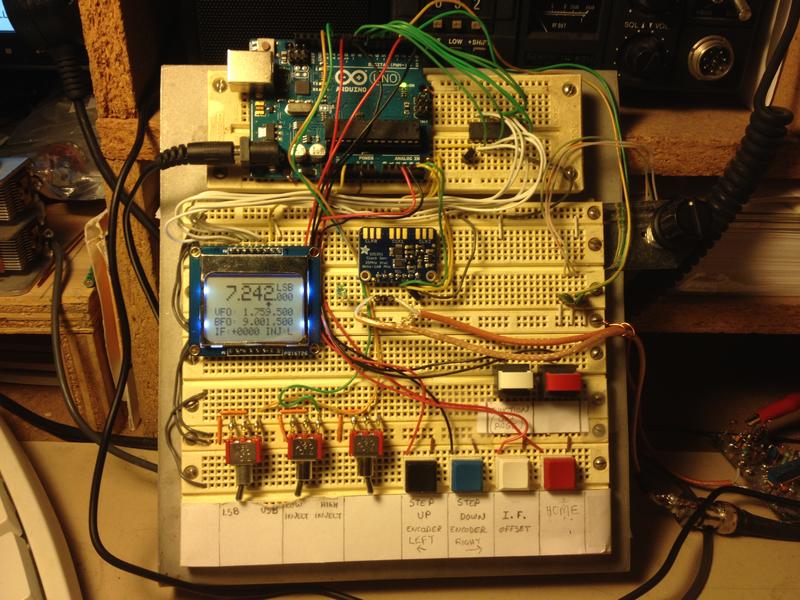
Rick’s Digital Board
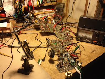
Ricks Rig as it was during our QSO
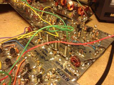
Crystal Filter
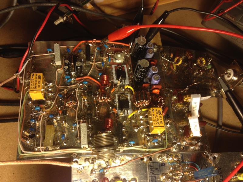
Rick’s Dual HEXFET Power Amplifier
Check out the N3FJZ QRZ.com page for more info.
CONGRATULATIONS TO RICK!
Mikele’s Croatian Zia and the N6QW Cult
I was telling Pete that thousands of years from now, archeologists will be puzzled when they find, in many remote corners of the world, strange homebrew electronic devices with the symbol “N6QW” emblazoned on them. Who, they will ask, was the cult leader N6QW, and how did he get his followers to build these devices?
Thanks to the work of Mikele 9A3XZ, Croatia will surely be a major center for research into the N6QW cult. Check out Mikele’s video. Stick around for the full 6 minutes and you will see the many N6QW rigs that Mikele has built. FB Mikele! Keep up the good work!
Bryan KV4ZS’s “Let’s Build Something” Direct Conversion Receiver
Bryan:
I think it sounds great! There is nothing really wrong with it — that is what 40 meters sounds like! Sure there is static. And those whistles you hear near the top of the band are the carriers from shortwave broadcast stations. You might have a little hum, but that should disappear once you get it all packaged in a metal box. Congratulations Bryan! You have done something that very few hams have done: You have built a receiver. 73 Bill N2CQR
………………….
Hi Bryan,
First let me congratulate you. That is one fine build and you may actually have absolutely nothing wrong!!!!!! I really must applaud your “squares”. They look like they were made on a CNC machine. Bravo!!!
You are operating the LBS without an RF amplifier and as such you are trying to make up the gain in the audio amp. I would say that the results you are hearing are very consistent with the DCR without an RF amp. Get the RF amps stage working and then run your test –you will find with the RF amp that at the gain setting you have for the video will be room filling. It actually sounds pretty good. You might also try connecting a 1 NF across the audio trimmer pot as that will cut down on the “hiss’ sound.
Concentrate on the RF amp stage and then re-run your test –you will see the difference.
Great build – very nice job.
73’s
Pete N6QW
………………..
Very nice!
Sounds pretty good to me in terms of noise – that’s what a direct conversion receiver sounds like (they tend to be very wide in terms of reception – static is normal… Welcome the world without noise reduction and DSP!!). DCR’s – because they are not run through a narrow IF filter – allow a very broad range of signals to get to the audio stage. So, for example, if you tune that around during a CW contest, you’ll hear a LOT of signals at the same time – versus only one or two at a time, once you have this run through the 4.9152 crystal filter. That’s the nature of the beast.
The 1nf across the audio trimmer definitely will help with reducing the hiss, although I must say my Kenwood receivers all have a similar amount of hiss and I prefer my radios with more, not less, noise (it lets me know what the band conditions are like…). I have noticed on my builds, however, that if you have a very, very high pitch WHINE on the other hand, that tends to be a bad solder joint or bad capacitor somewhere – probably on a capacitor – introducing an offset into your RF someplace it shouldn’t. What that looks like on an oscilloscope is the audio signal will have a large DC offset versus ground – almost always a bad solder joint on a capacitor—or a bad/broken capacitor–somewhere in the audio amplifier. That’s the same problem you get when you try to record audio sometimes from an external source (TV, radio, CD player) on your computer – DC voltage offset on the audio line. Kind of like what you might have heard on a stereo if you ever tried to switch to a channel where the input was hanging open.
Ben
KK6FUT
First Ever SSB Homebrew to Homebrew Contact by N2CQR. With…
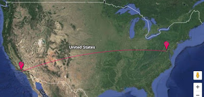
2322 miles. 3737 kilometers
Pete Juliano and I were talking on Skype yesterday evening. He was regaling me with tales of the wonders of his new beam antenna. He mentioned that he was working a lot of East Coast stations… Wait a minute, I thought, I’m an East Coast station. And I have a 20 meter rig sitting right in front of me. “Meet me on 14.190 Pete!” It took me a minute or so to get the rig connected to the CCI amplifier and the 20 meter dipole. By the time I got everything fired up, there was a station on the frequency. I thought we’d lost the spot. But no! I realized it was Pete calling me.
This was extremely cool. Pete was using his ZIA rig with the brand new beam. I was on my VFO BITX20. And I was using the CCI amp that Pete had coached me on (he taught me how to tap the holes for the heat sink).
This was the first time I had ever contacted another homebrew SSB station — and the first time Pete and I had spoken on the air. THE RADIO GODS WANTED THIS ONE TO HAPPEN!
I recorded the QSO:
http://soldersmoke.com/n6qwn2cqr.mp3
I will ask Pete to provide more detail regarding the California end of this QSO in the comment section below. Did you have your amplifier on Pete?
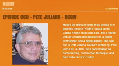
Listen to Pete Juliano’s Interview on “QSO Today”
Pete Experiences the Joy of Rotation
SolderSmoke Podcast #179 SPECIAL TENTH ANNIVERSARY EDITION

SolderSmoke Podcast #179 is available:
22 August 2015
YESTERDAY MARKED 10 YEARS OF THE SOLDERSMOKE PODCAST
— A clip: The first minutes of SolderSmoke #1
— A trip down SolderSmoke memory lane.
— The SolderSmoke lexicon — words and phrases we use (a lot).
BENCH REPORT
— Pete’s antenna project.
— Pete’s new Blog: http://n6qw.blogspot.com
— Bill’s big amplifier problem fixed thanks to Allison KB1GMX.
— Six digit freq readout with an Altoids case.
THE Si5351 PHASE NOISE CONTROVERSY
— ALL oscillators make noise.
— Keeping things in perspective: It is 100 db down!
— Observations and tests from LA3PNA, NT7S, and K0WFS:
— Try it, you’ll like it! The benefits trying things on real rigs.
NEWS
Interviews on “QSO TODAY” with Eric 4Z1UG.
Horrible band conditions.
Looking at Saturn with telescope.
MAILBAG
Another recruit for the CBLA: Paul KA5WPL.
Ron G4GXO on Bell-Thorn and Eden9 SSB rigs.
Rupert G6HVY on Kon Tiki radio and Mr. Spock.
Mikele’s Croation BITX rigs.
Dean AC9JQ’s TIA.
Bryan KV4ZS will build an LBS receiver.
Dave Anderson give Pete good antenna advice.
Steve Smith moves in from the garage.
Pete has built 12 SSB transceivers. Intervention time?
Our book: “SolderSmoke — Global Adventures in Wireless Electronics” http://soldersmoke.com/book.htm Our coffee mugs, T-Shirts, bumper stickers: http://www.cafepress.com/SolderSmoke Our Book Store: http://astore.amazon.com/contracross-20
Si5351 Phase Noise? A Tale of 3 Oscillators

Si5351 at 16 MHz
There is still a lot of talk about the supposedly horrible phase noise of the Si5351 chip. In a recent episode of a popular (and very good!) podcast about homebrewing, the podcasters talked about this in the context of some megawatt AM shortwave broadcast stations that had oscillator phase noise problems and were wiping out large portions of the HF spectrum. I don’t think those stations were running Si5351s, but the listener was left with the impression that these handy little chips are very noisy with lots of spurs and will inevitably produce horrible dirty, spectrally impure signals.
This has not been our experience. Following Pete’s lead, several of us are using the Si5351 to generate both VFO and BFO signals in our transceivers, with good results. The receivers sound very good and we have not heard complaints of “broad” or “noisy” transmitted signals.
I decided to dig into this a bit. This was also an excuse for me to use the FFT and screen capture features on my Rigol ‘scope.
I now have THREE BITX transceivers in the shack. My BITX17 uses a VXO at round 23 MHz (IF at 5 MHz)/ My BITX20 uses a classic LC VFO running around 3.5 MHz (IF at 11 MHz). Finally, my BITX40 (DIGI-TIA) uses the dreaded and much reviled Si5351 running at around 16 MHz (IF at 9 MHz). I thought that these three rigs would provide a good opportunity to test the scurrilous claims about the Si5351.
As a simple first test, I put my Rigol scope in FFT mode and just put the probe at the VFO Mixer’s LO input. The screenshot above is the FFT for the Si5351. It looks pretty clean to me. The ‘scope is looking at 15 Mhz above and below the VFO signal.

VFO at 3.5 MHz
Next I measured the output of the BITX20 VFO at the same point (input to the VFO mixer). (I had to change the vertical range, but the horizontal was unchanged.) Here you can see the second harmonic (just because at this low freq it is within the freq range setting of the ‘scope). It doesn’t look much different than the Si5351.

VXO at 23 MHz
Finally, here is the BITX17 VXO at 23 MHz, again at the input to the VFO mixer. It looks remarkably similar to the Si5351, don’t you think?
More on this to come. The ARRL Handbook (2002) has a good discussion on phase noise. I am digging into this and hope to do some more tests. For now, I think we should reserve judgment on the utility (for us) of the Si5351.
Our book: “SolderSmoke — Global Adventures in Wireless Electronics” http://soldersmoke.com/book.htm Our coffee mugs, T-Shirts, bumper stickers: http://www.cafepress.com/SolderSmoke Our Book Store: http://astore.amazon.com/contracross-20
Pete Noodles a New Antenna
Big doings at the Newbury Park Lab of N6QW. A new antenna is in the works. Lots of noodling underway. Much tribal knowledge is being dispensed (FREE!) via Pete’s blog:
http://n6qw.blogspot.com/
Our book: “SolderSmoke — Global Adventures in Wireless Electronics” http://soldersmoke.com/book.htm Our coffee mugs, T-Shirts, bumper stickers: http://www.cafepress.com/SolderSmoke Our Book Store: http://astore.amazon.com/contracross-20