
It is, truly, a thing of beauty.
Farhan will be posting details on his web site soon.
Category: India
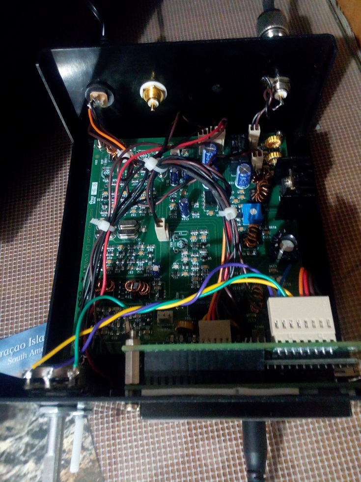
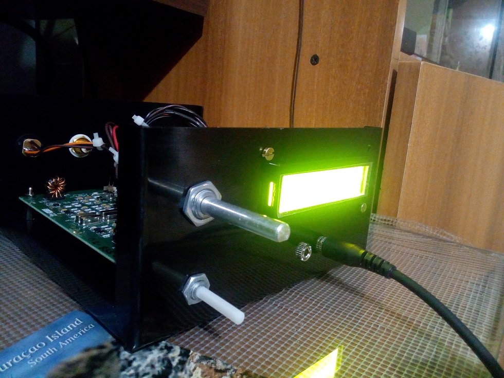
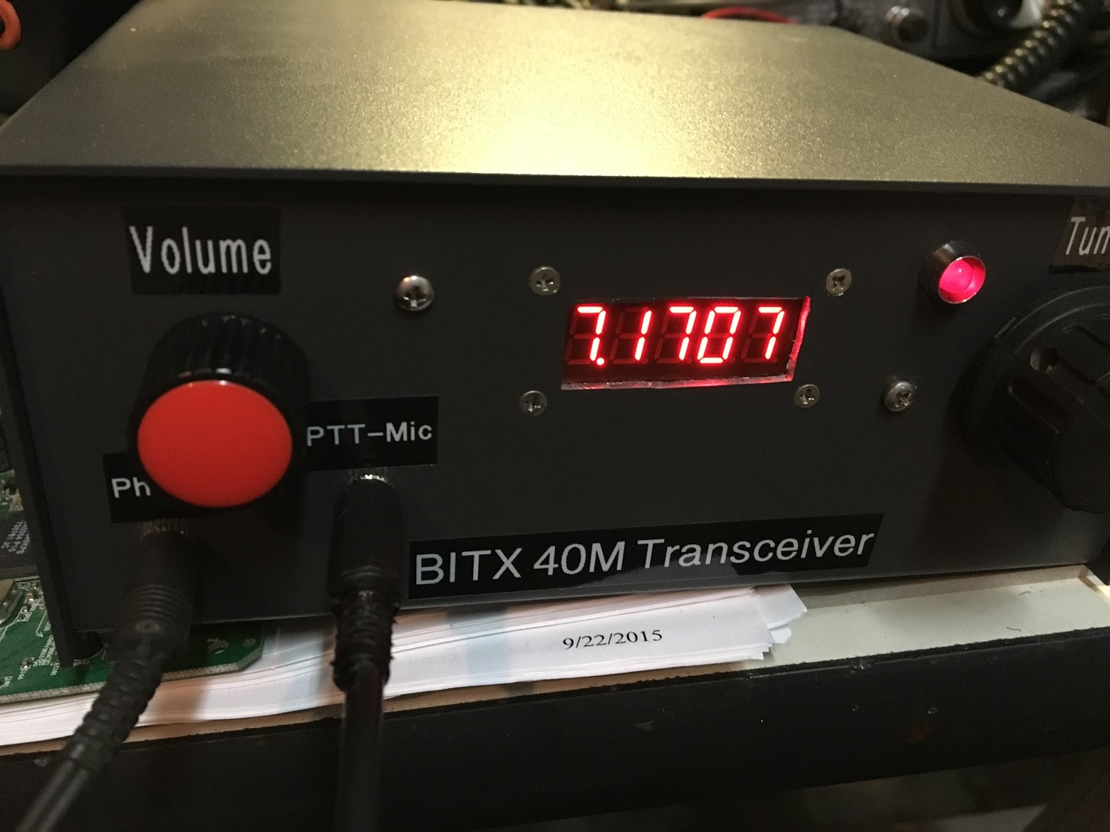
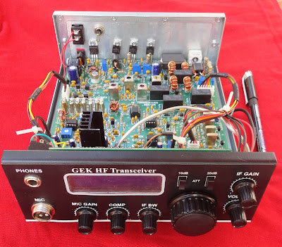
VU2XE’s BITX40 (with a cool CAD box)
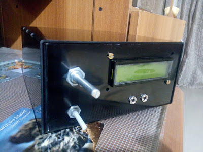
A year or so ago Pete and I encouraged Kiran VU2XE to try the BITX. He followed through, on our suggestion and went a step further, using CAD to design a box for the BITX. I will try to post a link to Kiran’s CAD files on the BITXHACKS blog.
Kiran writes:
Hi Bill and Pete,
It is almost year since you seeded idea about the BITX. I am still a listener of your podcast.
After finishing my RF amplifier project late last year, I was thinking of few projects and BITX was on the top of the list. I ordered and received a very beautiful BITX40 kit with Arduino, I got it recently. I also designed a simple case for it using CAD software. It can be used by anyone — just go to your local laser/CNC shop to get it cut in Aluminum. I just thought of sharing the excitement with you. This rig and it sounds awesomely good 🙂
Attached are some snaps and design files (I am no expert in CAD etc. it is my first attempt to learn and build)
Happy projects and 73s
Kiran VU2XE
SolderSmoke Podcast #193: BITX 40, OLEDs, KWM-4, Noise Abatement
SolderSmoke 193 28 Jan 2017
Report from Pete on BITX 40 Session with California radio club.
Update on the BITX40 Module Revolution
— Check out the BITXHACKS page. Send in contributions.
— BITX20 mailing list very active.
— Raduino!
— Interview with Farhan with W5KUB — Eliminating the commercial gear.
— BITX 40s on the beach in Australia. FB
— Check out the BITXHACKS page. Send in contributions.
— BITX20 mailing list very active.
— Raduino!
— Interview with Farhan with W5KUB — Eliminating the commercial gear.
— BITX 40s on the beach in Australia. FB
Bench Reports:
Pete:
— Color Displays!
— KWM-4
— OLED MADNESS!
— Color Displays!
— KWM-4
— OLED MADNESS!
Bill:
— Fixing up the old HT-37 HT37 to HT37 QSO with W1ZB
— Dabbling in VHF with Ramsey Aircraft band receiver. NOT FUN.
— Going all IC with Si5351 OLED NE602 rig.
— BANDSWEEP
— OLED Noise and the Active Decoupling solution.
— Fixing up the old HT-37 HT37 to HT37 QSO with W1ZB
— Dabbling in VHF with Ramsey Aircraft band receiver. NOT FUN.
— Going all IC with Si5351 OLED NE602 rig.
— BANDSWEEP
— OLED Noise and the Active Decoupling solution.
Using LTSPICE as a diagnostic or understanding tool.
Of Waterfalls, Homebrew Rigs and Casual Critics on 40 meters. Words of Wisdom from W8JI.
LEXICON: HAYWIRE TOMBSTONE BIKESHEDDING from Todd K7TFC
Some great recent interviews by Eric 4Z1UG:
Ian G3ROO Origins of ROO Regen at age 8
Hans Summers G0UPL Balloons! NO COMMECIAL GEAR
David White WN5Y ELECTROLUMINESCENT RECEIVER EXPLAINED
Rob Sherwood NC0B
Ian G3ROO Origins of ROO Regen at age 8
Hans Summers G0UPL Balloons! NO COMMECIAL GEAR
David White WN5Y ELECTROLUMINESCENT RECEIVER EXPLAINED
Rob Sherwood NC0B
MAILBAG:
Chris KD4PBJ’s BITX 40 with improved stability
Jerry W0PWE built a DIGITIA! Very nice. Worked Keith N6ORS and heard me! TRGHS
Mike AB1YK’s Al Fresco Scratch built BITX. But give that LC VFO another chance Mike!
Steve N8NM 30 meter rig with salvaged CB LC VFO. FB
Keith N6ORS Franken SDR rig with parts from the 1980s. FB
SKN Bandscan from Mike WA6ARA I worked W1PID Jim!
What is Mikele up to?
Rocking Johannesburg and Kirghizstan via local repeaters:

KD4PBJ’s FB BITX 40
Hi Guys!
I have to admit something. It’s a learning experience.
A year or two ago I bought the Bitx boards from Sunil in India and while they are on the To Do list, haven’t been built up yet. I have close to 20 projects on my to do list, so when Farhan’s prebuilt SMT version became available I decided to get one.
I had gone over to TenTec before they shut down and bought a few of their two piece enclosures since I like how attractive they are and also inexpensive.
The Bitx went into the enclosure quickly and I measured a little over 10 W out with my scope. I fed a -125 dBm signal in using my HP8640 generator and could easily hear the tone.
So a really sensitive receiver. Nice and quiet too!
I got a SMT digital dial from QRP Guys and got it in the case. Now I heard a high pitched whine in the background. Nuts!
So I posted to the Bitx yahoo group asking for help in reducing the noise. I built a R/L/C filter network, added ferrites, built a copper clad and brass enclosure for the display. Nada. Noise still there. Adding adhesive copper tape didn’t help either.
This was driving me mad. For some reason, and I don’t know why, one evening I decided to try a gel cell. Success!!! No noise whatsoever.
Here’s what happened….
When I first built the radio in early December I tested it on my operating bench. On that bench is a older Power Designs 0-60V 0-5A linear bench supply.
After adding the display I did integration on my soldering lab bench and for that I grabbed my HP E3610 supply which it turns out is heavy but switching, not linear. The noise was coming from the supply!!
If I hadn’t tried the gel cell it may have taken me a long time to figure this out.
Saturday of last week was my first contact with it. I worked two Canadian stations with it, and both came back to me the first time after I answered their CQ’s. I did have one issue and that’s the well documented drift. During the QSO I watched the display drift upwards as I held the PTT button down. I replaced the 100 pF and 47 pF chip caps in the VFO with disc ceramic parts from Mouser and now it doesn’t drift.
While doing the work in the VFO section I also tweaked the trimmer cap a bit to bring the bottom range up to the start of the phone band, as before the bottom end was below 7 MHz and I figured that didn’t do me much good for a SSB rig to waste a lot of its tuning range on the CW segment.
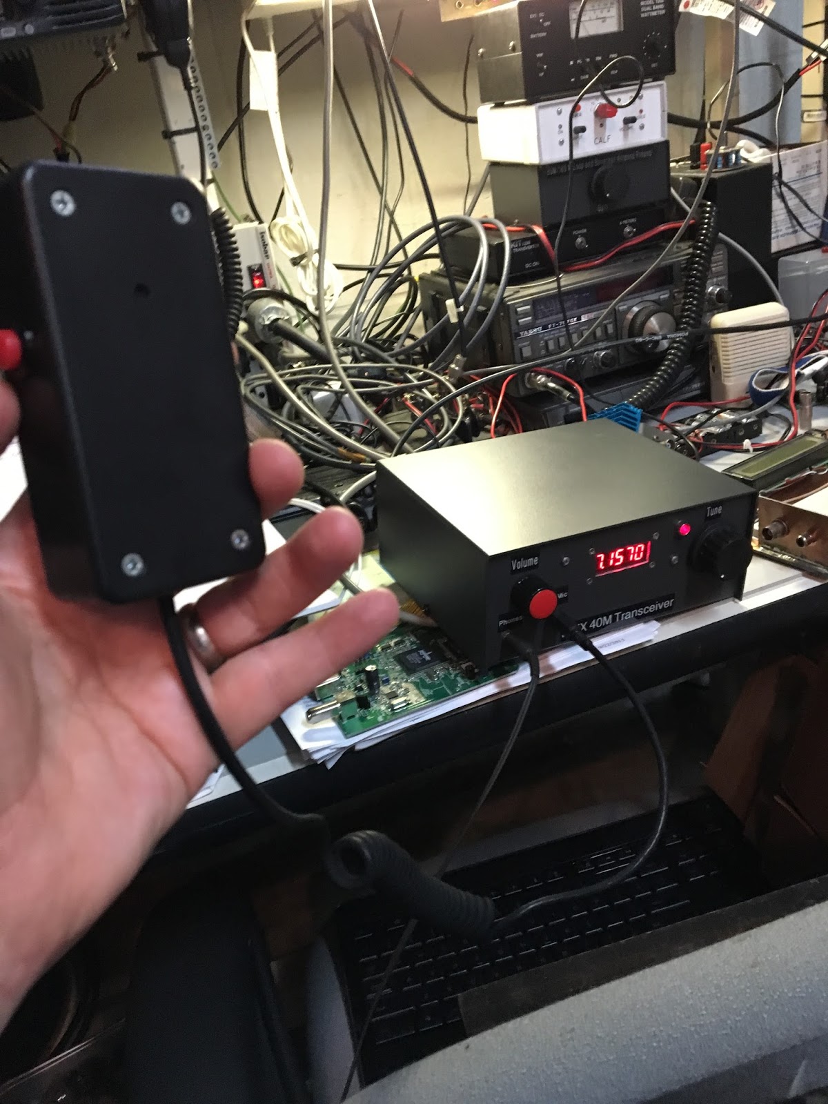
Here are a few pictures. Mic is home brew too, having made it for my MMR-40 rig.
Hope all is going well for you and looking forward to the next Solder Smoke.
Chris KD4PBJ
A Nice History of BITX 40 Module: Production and Finance
Some fellow jumped into the BITX20 yahoo group this morning, casting aspersions on our friend Farhan. The fellow alleged that a lot of money was being made on the BITX 40. He seemed deeply unhappy about the shipping materials and found fault with the documentation that came with the boards.
Farhan came back with a very gentlemanly and detailed response. He was a lot more patient and temperate than I would have been. And when I think about how Pete would have responded, well, it would likely have involved — at the very least — a lot of colorful words from Southern Italy.
Anyway, below (unedited) is Farhan’s response. I think it provides a lot of very interesting background info on our beloved BITX 40 Module and on the place that these boards come from.
thanks for writing in, I couldn’t get your handle from the mail, so do excuse me for improper address! I think you have raised from valid points. I think it is important that everybody understands what tried to do, what we did and where we are now.
this is going to be a long and full of personal details that i didn’t consider to be of any interest to the group and hence it was kept out. but i guess, i need to let a few cats out of the bag.
i am retired, early. i had a modestly successful run in a few businesses but i had promised myself to retire from active work, which i did around five years ago. i no longer run any for-profit businesses. most of my investment goes into ‘stuff that matters’. i founded a libera cultural space in hyderabad, i am a partner in a strategic venture fund that promotes technologies that are important rather than profitable. neither ehsan nor i are any longer running anything full time. i do mentor some startups now and then but never as an investor.
i would be only too glad if someone else takes over the entire hfsigs approach. the design has been out in the open for more than a decade. apparently, it doesn’t make economic sense to make them at $45 dollars a pop. so, there is nothing preventing others ‘creaming the market’ if they want to. surely, the turnover is modest but it is not profitable.
it is fallacy that India is cheap. In Hyderabad, a modest apartment will cost you over 250K USD. An independent house in a reasonable area goes for a million USD. A gallon of gas will costs you more than 5 dollars. smart people are hired by facebook, google and microsoft. they have a big a presence here as in the valley and seattle. there is no healthcare, all education is privatized and has to be paid. there is no social welfare. the multinationals they pay top dollar and that drives the living index up, not down. a quick indicator is that only 7% of the population of Hyderabad moves in cars and taxis and they account for 85% of the traffic congestion. our purpose is not provide the women who work low wages, but respectable wages. but i am getting ahead of myself…
Two years ago, our local club conducted India’s annual hamfest. As a part of the delegates kit, Ehsan and I decided to put free BITX PCBs in the kit. These were done without any commercial interest. At this time, the hamfest was still short of money, so we decided to buy the back page ad of the souvenier to help them with the money. I had to put in something in as text, I decided to put a message in the name of HF signals (which was the name of the wiki that is still up at www.hfsignals.org). We distributed a 1000 PCBs for free. Only a few turned up on Air. It was time to do something.
Later, in 2015, I decided to conduct a workshop to help those interested in assembling the PCBs. asked them to get the components off the local shops and we settled down to do it. i discovered that a seemingly simply job of scrapping the enamel off a copper wire would take them hours and often they’d end up doing it the wrong way. the PCBs were badly designed too. we aborted the attempt. i had learnt something : homebrewing cant be taught in a day. first fail.
i also figured that it might be easier to begin with something that is already working and then start modifying it. something that happens in open source all the time. so,i sat down and designed a new single side pcb .. with through-holes, on Express Pcb. we turned up 100 boards, found a group of five young girls who were laid off after the unit where they worked to assemble TVs had closed down. showed them how to assemble the boards. they made quite a few mistakes. the transformer windings got mixed up, resistors got swapped, the transistors were inverted, etc. each board was an adventure. you can probably see some pictures of these boards floating around. they were cheap to produce. the actual component cost of the bitx is ridiculously low. it cost us about 1000 rupees in components, another two hundred for the assembly and testing and a hundred bucks to ship it. we rounded it off to Rs.1500. About 100 of them were sold. it gave me nightmares. each board took an hour or more to fix. i decided not to do it at all. we rolled up the operations after a while. second time, fail.
by now, i had given up on doing anything with bitx boards. but a conversation with convinced me that SMD might be the way to go. we looked around and found a local SMD shop that agreed to do small runs for us. the smd components are much more expensive in india. we decided to keep the more expensive components like crystals, electrolytics in through hole format. i had to learn kicad. the women were now retrained to do the windings, insertion of through hole components and two rounds of testing. the component cost was at Rs.1500, another Rs.200 to the SMD insertion machine, Rs.200 for through hole insertion, testing. add another Rs.100 for packing and Rs.100 for local posting. we were selling these for Rs.2400 inside india and 45 dollars (a few hundred more to cover the additional expense of international postage) outside.
now, we come to the packing and shipping saga. the DHL/Speed Post quoted above Rs.1500 for shipping it internationally. that would be nearly 60% of the board’s sale price. instead, we looked at the ordinary postal service. so, we bought some amazon shipping cartons, assuming that these must be good enough for us as well and shipped some boards to friends around the world. we shipped five of them with the boards in bubble wrap. all fo them arrived in good shape. we rolled with this. WE USED BUBBLE WRAP. When we started actual shipping, we realized that the bubble wrap wouldn’t prevent the carton from collapsing. the coils were getting damaged. we needed some kind of a stiff roof over the board so the box’s sides wouldn’t collapse down. That’s when we started using the foam plate over the board. The foam provides a physical shield for the coils. The foam + the amazon cartons worked for a while. Then, we ran out of cartons.
Diwali is the christmas equivalent in India, the packing materials just disappeared from the market. we looked around and bought some other cardboard gift box. we sent them out as gifts to another set of people, they reported no problems, so we continued with those. after a while, we started getting complains about those boxes as well. then, we started looking around for something else.
we found these plastic boxes to be sturdy. we tossed them around, shipped them to a few volunteers around the globe and finally agreed that these were holding up. so we continued with these boxes. these boxes are costly. they are not ‘cheap’. i am personally averse to using plastic, but we thought that these were the best for the purpose. if anyone has a better idea, do test it out and let us know. we are always glad to accept anything better.
2.) Secondly, components and PCBs in the Indian market are generally available at a lower cost, sometimes much lower, than components purchased from prime US suppliers such as Mouser, Newark, etc. The US is one market, India is another. That’s the way it works. Components even cheaper than these: http://www.ebay.com/itm/Reel-O f-3000-MuRata-0-1uF-Multi-Laye r-Ceramic-Surface-Mount-Capaci tors-25V-X7R-/161765931843
we buy our toroids from w8diz. these are genuine micrometal parts. the pcb is of high quality made to ISO-9000 standards. we import components from mouser. the only thing that we do on the ‘cheap’ is that we use microprocessor grade crystals that we sort out manually.
What’s the current serial numbering up to as of December. Anyone know? It was #465 in early December. 465 units multiplied by $45 USD is about $21,000 USD. That converted to INR has the purchasing power in India of $70,000 USD here in the US. That’s a lot of bread.
we have shipped 1000 boards. we got 45,000 dollars in revenue and we have not yet recovered our expenses. i have provided you with the figures. add them up. as i said above there are far easier ways to follow to make money than bother with these boards. that’s why no one else is doing it. the design is in open source anyway.
What’s my point?
Seems like with that kind of wealth in play:
1.) The product could be double-boxed and well bubble-wrapped so it arrives undamaged after it’s 12,500+ km trip from Hyderabad. Old candy boxes or scraps of waste paper taped together just isn’t doing the job. Broken product means unhappy customers and a bad reputation.
as i said, bubble wrap didn’t work. there will be enough people here to vouch for that. we did try it.
2.) The single schematic that represents the functionality of the product could be up-to-date and error-free.
this is the schematic that was used to produce the PCB. where are the errors?
And for totally optional bonus points: A section by section Theory of Operation write-up that explains exactly how all the sections operate and how to troubleshoot. If a template is needed, look at vintage HP test instrument manuals or Heathkit ham radio transceiver manuals. Hint: Saying that, “It’s all been explained many times before on many forums, Google it.” does not get any points.
surely, it could be done. probably it is already done. bitx happens to be most well documented radio now. it is a community effort. look at http://golddredgervideo.com/kc0wox/ and soldersmoke and arv’s work and the large amount of stuff in the file section of the bitx group and you will realize that more people know, understand and write about bitx than a proprietory manual might contain. if you think it is lacking, go ahead and write some more documentation.
oh, btw, Ehsan is not an Ayn Rand supporter. He is a radically liberal guy who is more at home with the socialists at lamakaan than the suits of the software gang.
– f
Big News! BITX 40 Module Gets Digi Side Car! Raduino!
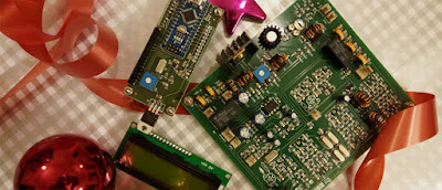
A very nice Christmas present from Farhan in Hyderabad! An Si5351/Arduino Nano VFO for the ALREADY AWESOME BITX 40 Module. I’m really glad Farhan kept the digital stuff on a separate board — it just seems like the right way to do it.
Details on http://hfsigs.com
India’s Successful Mission to Mars (Video)
NPR’s “Science Friday” produced this very nice video on India’s successful mission to Mars. Really nice.
The Nauen Transmitter Station (Germany)

There is a lot of radio history in this shortwave transmitting station. I came across it tonight with my BITX DIGI-TIA rig. It was on 7.215 MHz transmitting in Indian (South Asian) languages. But alas, the signals were not from distant India (home of the BITX!). Instead — as often happens these days — the signals were from a relay station. In this case they came from relatively nearby Germany, from the Nauen transmitter site.
Check out the Wikipedia page:
https://en.wikipedia.org/wiki/Nauen_Transmitter_Station
A Charming Detail About the BITX40 Module
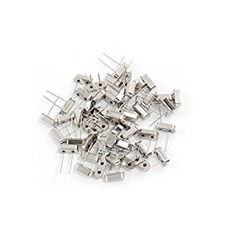
In the BITX20 yahoo group, Farhan responded to a question about the BFO and the crystal filter in the BITX 40 Modules. In his response we learn more about the work of the members of the women’s collective. Uma is the name of the lady who has the job of sorting the crystals. She sorts 1000 a day:
Farhan writes:
There is a longer explanation to this. The crystals we use in the BITX are microprocessor grade. This means that they are not very precise. Uma is the crystal sorter. She takes a bunch of 1000 crystals a day and sorts them by their frequency into different bags. Each board takes its five crystals from any one bag. Hence, the central frequency of each board will be slightly different from another board.
The central frequency of the ladder filter moves down from the oscillating frequency of the same crystal. That is why, in a set of matched crystals, one can be directly used as the carrier/beat frequency oscillator without needing any trimmer : it directly sits on the higher side skirt of the filter.
The BITX40 board’s BFO usually ranges from 11.990.0 to 11.997.0, though in almost all cases it is very close to 11.998.0. The best way to determine the BFO frequency is to take it another ham’s shack, tune in the BFO to zero beat on USB or LSB and note the frequency. I use the Rigol scope’s built-in frequency counter to measure it off the modulator transformer’s primary.
So, the IF offset should ideally set to the measured BFO’s frequency. These are however, very subjective choices. Given that 2.2 KHz is not an ideal passband, 3 KHz is more like it, setting the BFO will determine how you would like to hear the receiver. Setting it close to the passband will make it bassy, setting it away will make it tinny. Setting it a few hundred hertz away will make it hollow. You get to choose which way you want to make your radio sound bad (harr! harr!)
– f
TRGHS! HB2HB! Homebrew Extravaganza on 40 Meters!
 |
|
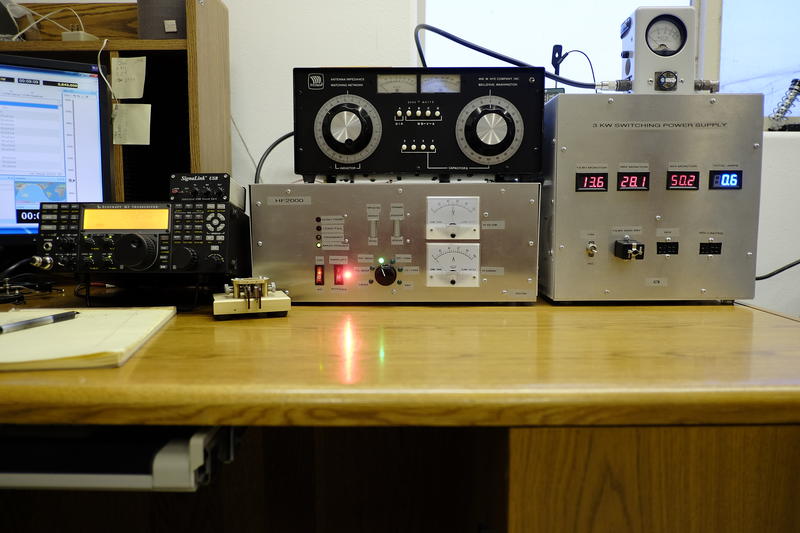
AC7M HB Amp and HB Power Supply
|
I was flying solo last night. Everyone else in the house was out. So I turned to ham radio for some company. And I was rewarded.
I called CQ with my BITX DIGI-TIA rig and was immediately answered by Doc AC7M in far-off Twin Peaks, Idaho. Doc was running a K3 to a homebrew solid state full gallon amp. And get this — Doc had also homebrewed the 3 kw switching power supply. I looked at my store-bought supply and felt like an appliance operator. I hang my head in shame.
As we discussed solid state amplifiers, we were joined by another builder of silicon after-burners: Don K9AQ, who called in from a beautiful cabin in rural Wisconsin. Don’s amp is based on the venerable EB-104 design.
Both Don and Doc talked about the work of W6PQL. He has a really amazing site devoted to homebrew solid stat amps, and he is selling lots of great boards and parts for this kind of project:
http://www.w6pql.com/
As I finishing up with Don and Doc, I got a very welcome call from an old friend from the SolderSmoke community: Dino KL0S. He as booming in from Williamsburg, Va. Dino has an amazing workshop. He is building a serious vertical antenna for 160 meters. Dino is going for the DX.
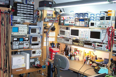 |
| Dino’s Bench |
At this point Mike WA3O in Pittsburgh called in. And get this: Mike heard me on his new BITX 40 Module. The Radio Gods Have Spoken! (TRGHS!). We switched up to 7.285 MHz where I fired up my BITX 40 Module for a BITX40-BITX40 QSO (albeit not at QRP levels).
We should definitely make more use of 7.285 for BITX40 and other HB QRP SSB QSOs. 1930 EST (0030 Z) seems like a good time.
Finally, just when I was thinking that things couldn’t get any better, they did: Armand WA1UQO called in from Richmond. Armand and I collaborate on parts acquisition at Virginia hamfests. We specialize in the contents of the musty cardboard boxes found under the tables. We discussed the DISRUPTIVE influence of Farhan’s BITX 40: All around the world, other homebrew projects are being literally pushed aside on workbenches to make room for that fantastic little module from Hyderabad.
I was very pleased to hear that Armand is building an analog VFO for his module, using a coil in the 4 uH range, wound on a piece of cardboard tube from a coathanger. The inspiration for this kind of coil (which I now have in THREE rigs) came from Farhan, who used sipping straws from fast-food restaurants as coil forms in a sig generator that he built years ago. This week, seeing a Facebook picture of my daughter and me in a restaurant with drinking glasses in front of us, Farhan asked if I had brought home the straws.
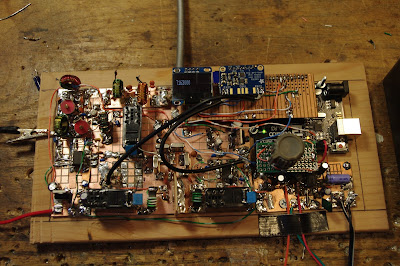
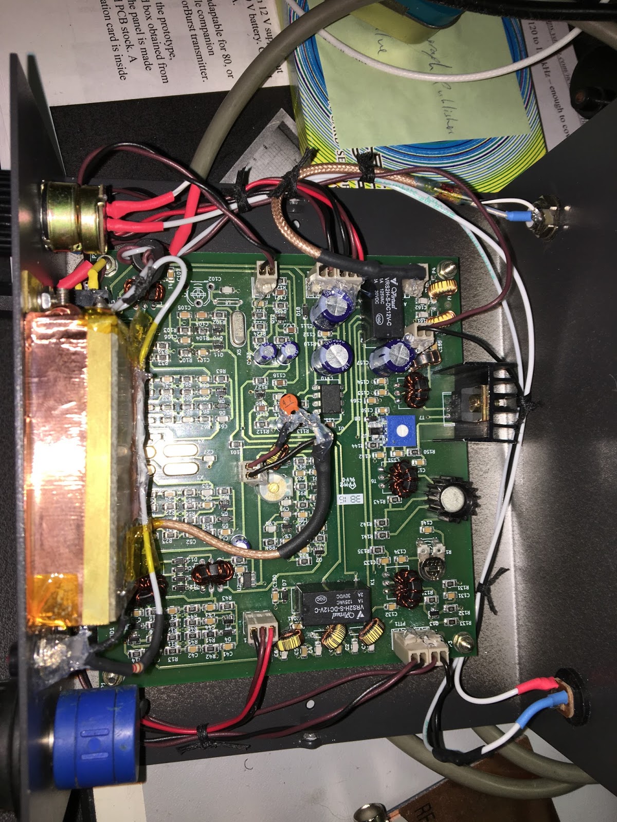
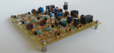
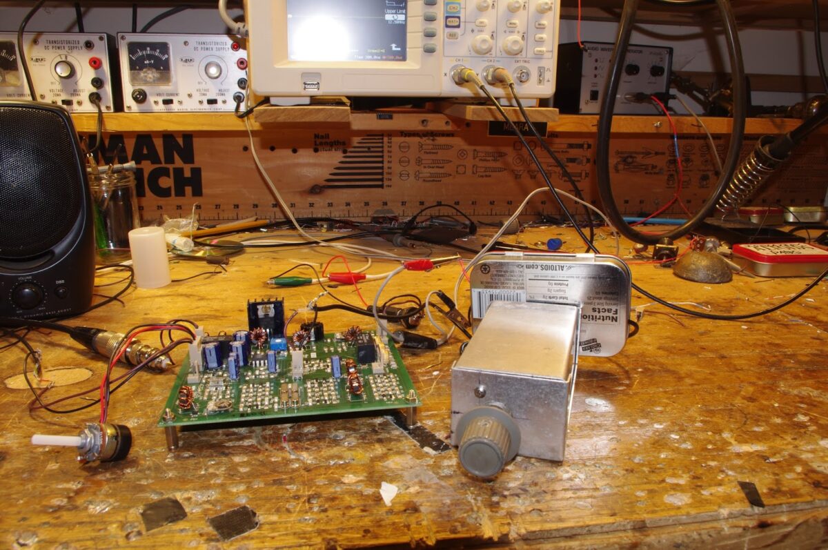
My Extroverted BITX40 — On (but not in) a Box
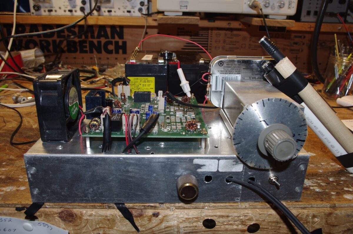

I was going to put the BITX40 Module in a box today, but I just couldn’t bring myself to do it. That board looks too good to be hidden inside a box. So I put it topside. That’s the analog VFO to the right. You can see a fan off to the left — that is perhaps temporarily in lieu of a large heat sink for the final. You can see the two Gel cells in the background. I am indeed running 24 volts to the final, and am putting out about 20 watts. I had three nice contacts today on 40: WB2RON up on Long Island said I was “20 over”. Later I worked W1SJ in N. Vermont — I was 5-9. Then — icing on the cake — DK1NO in Stuttgart. I was 5-8. TRGHS.
I kind of like this arrangement — it has the “three dimensional” feel of an old tube rig. This obviously wouldn’t be good for portable operations, but I am not planning on going portable. There is a lot of room under the chassis. I could put a digital VFO in there and put in a switch so that I can easily go from digital to analog.
Two Gel Cells and a Heat Sink — BITX40 Power Hack
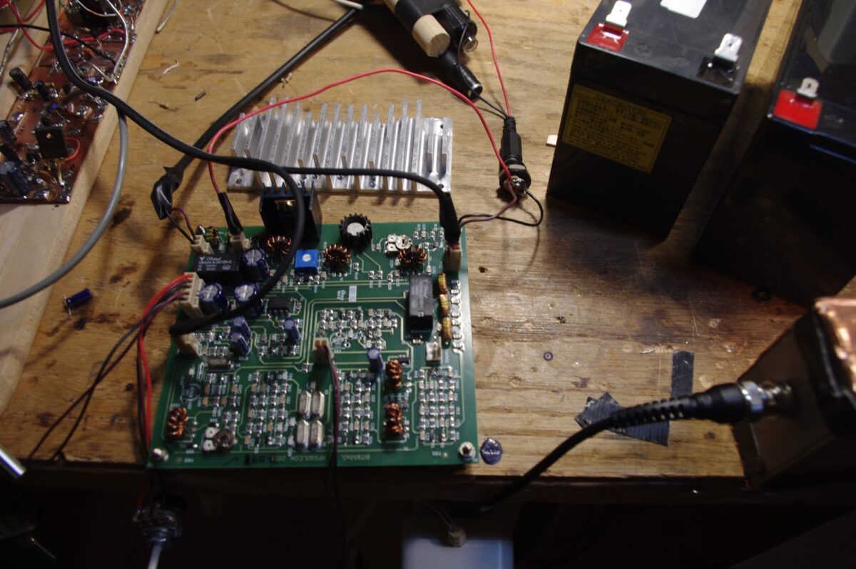
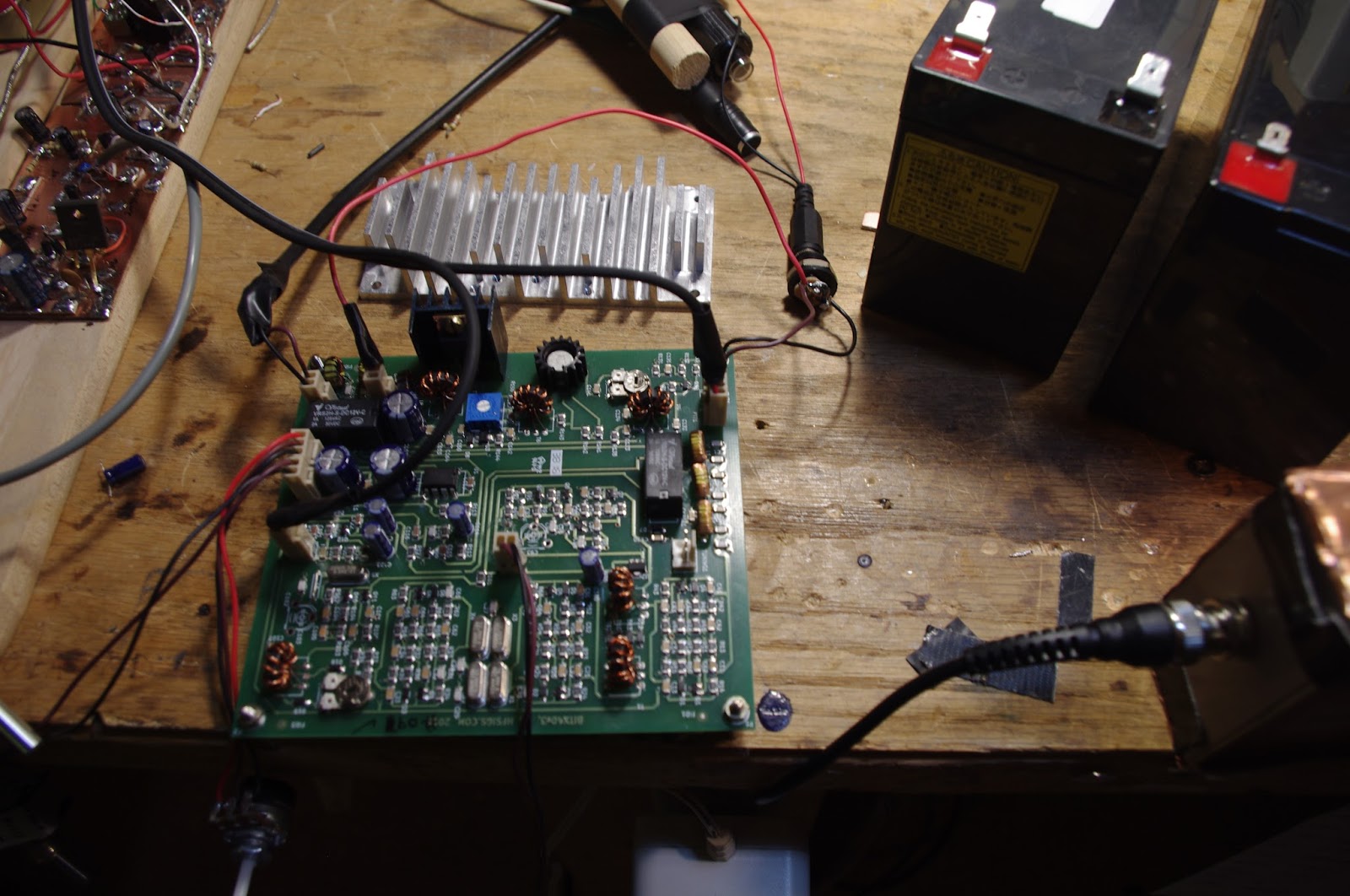
I blame Pete for this. And Farhan. Pete has been leading us astray with all his talk of high power linear amplifiers (“Two 813s kid, that’s all you need!”). And Farhan practically pushed us beyond QRP limits by placing a separate DC power connector for the IRF510 final amplifier on his new BITX 40 Module board. Farhan writes:
There are jump-points from where you can add more modules like the DDS, more bands, better audio amplifier, etc. Imagination is your limit. You can separately increase the power amplifier’s supply voltage to 25 volts to be more than 20 watts of power : You will have to add a better heat sink. The mods are on the way! (from hfsigs.com)
A while back Chris KD4PBJ sent me some very nice heat sinks — one of those would fit quite nicely on the PA side of the BITX40 board. And I just happen to have two 12V Gel cell batteries. One will power the board and the two together will power the IRF510. With 20 watts out to my dipole I feel confident that I will WIN the upcoming ARRL Phone Sweepstakes (in my category: Homebrew VFO, Northern Virginia).
Reverse Polarity Protection
When I opened the package from India and saw Farhan’s s beautiful board with all those little SMD parts, I immediately worried about frying those parts by accidentally reversing the polarity of the 12 volt DC input. Believe me, this can happen. It is especially likely during the early, enthusiastic testing and experimenting that takes place in the days after the arrival of a new rig. So, my friends: Save yourselves the agony of fried components! Don’t let your BITX 40 Module go up in smoke! Install a simple reverse polarity protection circuit BEFORE you start working with your new board.
Here is what I did: I just took a diode (a fairly hefty diode) and I soldered it in between the pins of that neat little circular power jack that Farhan sent with the module. Be sure to solder it in so that it does NOT conduct if you have connected the power correctly. The arrow should be pointing to positive terminal. Then put a fuse (3 amp or even a 2 amp) in the line from the connector to the power supply or battery. If you don’t have a holder you can try just soldering the fuse into the line.
With these two little parts, you can save yourself a lot of grief: If (WHEN!) you connect red to black and black to red, that diode will conduct like crazy and will blow the fuse. You’ll just have to replace the fuse (and not the module).
Hacking the Hackable BITX 40 Module: VFO is the Way to Go!

I am having a lot of fun with Farhan’s new BITX 40 Module. I think I’m doing exactly what Farhan intended people to do with this rig: work on it, modify it, improve it.
I’ve been working on frequency stability. I was, I admit, skeptical from the start about the stability of a thumb-sized, SMD, varactor-tuned VFO with a ferrite or iron powder toroidal coil. Don’t get me wrong — it worked. But it drifted. It seems to me that it would be asking too much to expect a VFO like this to be drift-free. (But I may be wrong — are there any SMD, varactor-tuned VFOs out there that DON’T drift?)
First I thought it might be the 9 uH metallic core toroid. So I replaced that with a 10uH choke — no ferrite or iron powder in there. That seemed to help a bit, but SSB QSOs would still quickly drift into Donald Duck chatter. Then I thought it might be the varactor diode. I let it warm up. A lot. Still, it drifted. Then I thought it might be the trimmer cap, so I took it off the board. No change. During this process I noticed that even slight pressure on the board caused the rig to shift frequency. I began to suspect that the drift was just structural — a consequence of the physical characteristics of the SMD parts and the board. To get VFOs stable I’ve had to build them big: 10 X 10pf NP0 caps to make one 100 pf cap, large air-core coils, and big sturdy variable caps. I’d isolate the frequency determining elements in a box separate from the powered components. This little VFO just looked too small to be stable.
So faced with drift, at first I asked myself, “What would Pete do?” I took an AD9850/Arduino combination off the shelf and plugged the output into the “DDS” jack Farhan had placed on the board. I removed the 10uH choke. Viola! With the DDS tuned to 4.7 – 5 MHz, the receiver worked great. I briefly tried to updated the Arduino code to take into account the 12 MHz IF (so I could get an accurate frequency readout), but ran into the old painful Arduino IDE problems: Now it is claiming there are library problems. Not wanting to suffer through another round of digi-agony, I left well-enough alone. I used the DDS with the old code for one day.
But of course, I was not satisfied. Attaching a DDS or PLL synthesizer to the BITX 40 Module just didn’t seem right. Heck, it was kind of like just hooking up my FeelTech Chinese sig gen to the DDS jack. Farhan’s rig is simple, beautiful and ANALOG. The parts are small, but you can see them. You can put your scope probe on the collector of Q7 and see what is going on. DDS or PLL. It is a REAL HARDWARE-DEFINED RIG. So I decided to build a VFO. Pete calls VFO’s “grief machines” but for me, the grief machines are those little Arduino beasts. To each his own.
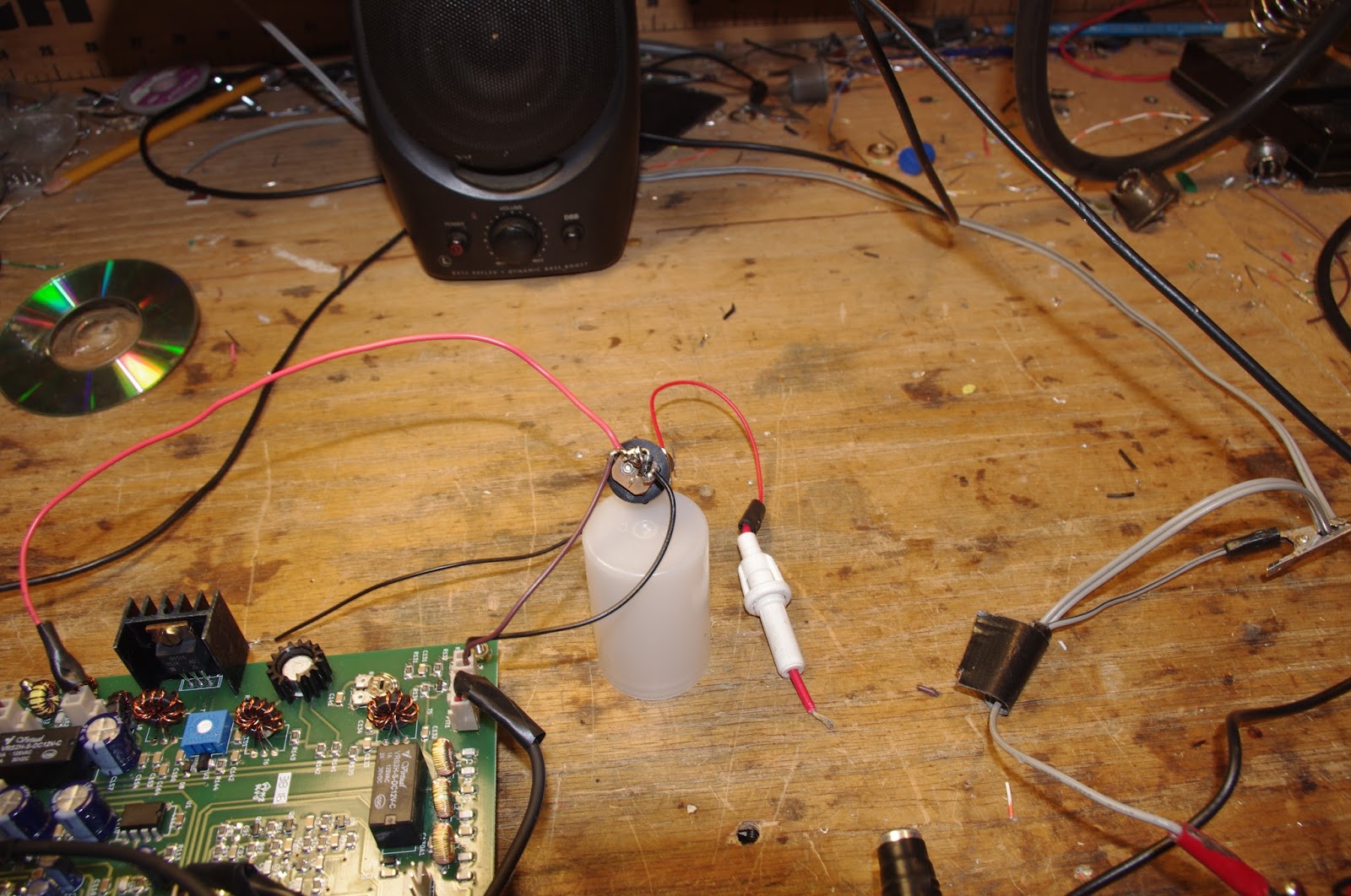
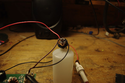
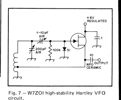
When I build a VFO, I start with the variable capacitor and the reduction drive. I found a nice one (with reduction drive) in my junk box. I tunes from 40 pf to 56 pf. I decided to use the super-simple Hartley circuit presented by Wes Hayward W7ZOI in SSDRA (page 34, fig 7).
I went with a 4.4 uH air core coil (wound on a cardboard tube from a coat hanger). Consultation with on-line resonant frequency calculators showed that I’d need to put about 180 pf in parallel with the variable cap. For this, I used a bunch (maybe 10?) of small value NP0 caps in parallel. This really helps keep the VFO stable.
As I did with my HROish receiver, I put the coil and the caps in one box, with the MPF-102 and associated parts in an attached Altoids tin. Everything was glued and bolted down very solidly.
I only built the actual oscillator stage — I decided to use the buffer amps on Farhan’s board.
The oscillator started right up. I had to add and then take away some turns on the coil to get it to run in the desired range. Then I plugged it into the DDS jack — the receiver was working immediately.
I noticed, however, that it seemed a bit less sensitive than it had been with the AD9850 DDS. And when I grabbed the wire going into the DDS connector, audio output jumped dramatically. It took me a few minutes to figure that out: I think the output from my VFO was not adequately turning on the diodes in the diode ring. When I grabbed the wire, I was putting a lot of noise into the mixer port, probably turning the diodes more fully on (but also letting a lot of noise through).
Fixing this problem part was fun: Looking at the BITX 40 schematic, I saw that the two 1000pf feedback caps in the original oscillator were still in the circuit. I figured those caps would be sending a lot of my VFO energy to ground. So I fired up my hot air rework station and deftly removed C91, the 1000 pf cap that is connected to the base of Q9. Instantly the receiver started inhaling as it had with the DDS VFO. That was a very satisfying fix.
This whole VFO project was very satisfying. It was all done in one day, and all the parts came out of my junk box. I think I ended up with an LO frequency source that matches up in a pleasing way with the analog circuitry in Farhan’s rig. And here is bonus that I think is just what Farhan had in mind: this kind of circuit adds a definite homebrew element to the module rig.
I found that this external VFO improved stability significantly. I don’t know if it is as stable as the DDS, but with the external VFO the receiver no longer drifts away as I listen to SSB signals.
Farhan on What’s New in the BITX 40 Module
Writing to the BITX e-mail group, Farhan provides some very interesting information on the philosophy behind his new BITX 40 module, and on how it differs from earlier BITX designs:
The new builders are often caught in a catch-22 : to get on air they need to build a rig from scratch. but to build a rig, they need lots of experience. A way out was to provide working boards where we can get on air quickly, and then start improving and modding the circuit. this is the spirit behind the new boards. Consider them like you would consider a raspberry pi or an arduino : simple, working circuits around which you can grow your own radio.
In the new bitx boards, I have tried to keep as close to the original bitx as I could. however, there are a few departures that I thought the bitx builders here would like to know about.
i have to admit though, strangely, i am less familiar here with bitx than many others on this form. arv, leonard, dan, andy and others have build far many more version than I did. I just happen to be the first one to build a bitx. this as much an acknowledgement of their inputs. without all you folks, bitx would not have had the kind of traction that it now enjoys. I suspect that it is the most built transceiver in the world.
So, here are the changes from the original bitx.
1. SMD
The SMD components make for virtually error free boards assembly. We used the biggest sized SMD components. In fact, the resistors and capacitors are about the same size as a quarter watt resistor that is soldered standing up. They are very easy to desolder without messing around with the desoldering wick and solder pumps. All you do is to lay the soldering iron’s bit on the component such that the flat end touches both sides at once and after a few seconds just drag the component away. I soldered the sample boards with my regular, 2 dollar, 25 watts iron without using a magnifier (I wear reading glasses).
1. 40 Meters
It is just that with the sunspots fading away, 20 meters in the tropics is far less active than before. Many of the us South Indian hams hang out on the lower end of 40 meters every morning and evening. Hence, the choice. That doesn’t mean that i can’t be converted to 20m! There are several ways to change to 20 meters. Keeping the VFO same, change the crystals (and hence the IF) to 8.833 MHz and rework the band pass and the low pass filters. I will work out the details in a few weeks and post them here.
2. A new bandpass filter
The original bandpass filter was quite lossy. I didn’t know how to use any CAD tools when i sketched it. I was actually on a long haul flight when I designed that filter. The new filter configuration is very interesting one. I saw it on PA3AKE’s site. This is a triple tuned circuit with very good out of band attenuation while maintaining very low loss.
In the last then years, ecomm has made it possible for us to globally access good quality toroids anywhere in the world. Hence, we have used T30-6 toroids with excellent low loss. I measured it at just 2 db, the original had more than 6db loss.
3. VCO
The original oscillator on the BITX used a variable capacitor. These were noisy, and often of inferior quality. In any case, they are no longer available. Instead, we have used a varactor diode for tuning. The greater benefit of using a varactor to tune the oscillator is that the tuning control only carries a DC voltage. You can install it anywhere. If you need finer tuning control, you can add a second lower value tuning pot in series with the main tuning pot. It is easier to add FLL to a VCO.
4. Audio muting
The original BITX used just a switch to move from receive to transmit. The receive voltage charged receiver’s audio preamp’s decoupling capacitor and it took time to discharge. this kept the audio preamp active even on transmit and caused a very sharp audio noise on the transmit change over. Now, the other section of the T/R relay is used to cut the audio off to the LM386 as soon as transmit line is energized.
5. A better T/R system
The original bitx didn’t have a PTT. this one has two relays to switch the linear amplification chain in and out of the circuit, mute the audio and change over the antenna. These changes lead to a very stable linear amplifier and smoother change over.
6. Mic amplifier
The original mic amplifier easily saturated. The new design, thanks to dan tayloe, has a better head room and provides very clean modulation.
7. The fixed BFO
Though the PCB has the provision for a trimmer and an inductor to pull the crystal frequency. I discovered that with five matched crystals, if you used 4 in the ladder filter, the fifth’s frequency fell right into the perfect sweet spot for LSB work. You might need to add the trimmer and an inductor back for USB work.
8. DDS connector
To use the DDS, you will have to remove L4 (the VFO inductor) and inject the DDS/PLL output into the connector provided.
There are some smaller mods that people can try out:
* The current in the receive amplifiers can be reduced if you don’t have any radio hams in your neighbourhood who run kilowatt amps.
* The capacitor between pins 1 and 8 of the LM386 can be removed if you prefer headphones to speakers.
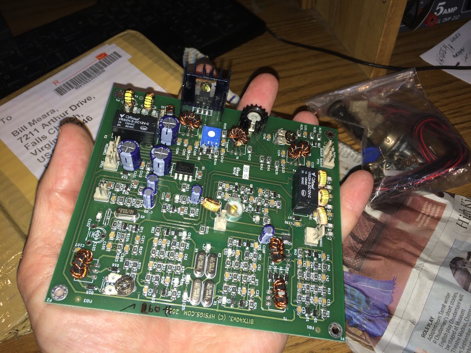
A Package from Hyderabad: Farhan’s BITX 40 Module Arrives in Virginia

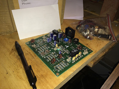
I am having a really EXCELLENT radio morning here at SolderSmoke East coast HQ. I made some progress on the Armand HRO receiver — just squaring away some of the too-long leads and improving the shielding a bit. Then I was looking out the window as the mailman arrived. What was that little box he was leaving us? Wow! A box from Hyderabad! The BITX 40 module arrived, wrapped in a very interesting piece of Hyderabad newspaper. Very FB. Thanks Farhan. I will surely be writing and talking about this rig in the weeks to come.
UPDATE: I just realized that the BITX module fits very nicely into a TenTec TPC-45 cabinet that Armand gave me a while back. TRGHS.
Update on Farhan’s BITX 40 Module
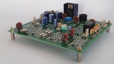
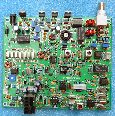
It is truly a thing of beauty: http://www.hfsigs.com/
The boards come assembled (as seen above). You can then add peripherals and modify away. It is “hackable.”
Hackable
The BITX40 will inspire you to experiment. Modify it, mount it, tweak it, change it.
The PCB uses all analog large sized SMD components that are laid out on an easy to understand manner on a double sided board with broad tracks. This can be your main module around which you can start experimenting. There are jump-points from where you can add more modules like the DDS, more bands, better audio amplifier, etc. Imagination is your limit. You can separately increase the power amplifier’s supply voltage to 25 volts to be more than 20 watts of power : You will have to add a better heat sink. The mods are on the way!
The board can be installed inside any box that you like. Make your own station rigs, man-packs, trail radios or mount it in a cigar box and leave it on your bedside table. The tuning capacitor has been replaced by a varactor tuning so you can place the tuning knob anywhere as it only carries a DC voltage.
Farhan writes:
For the last few months we have been working bringing low cost, tested SSB boards. Finally they are here. Priced at Rs.2200 At the moment, they are available only in India until we sort out an inexpensive way to post them to other countries. Visit www.hfsigs.com and pick up one!
The BITX40v3 is a complete 7 MHz SSB transceiver on a board that puts out 5 watts of clean audio and it has a very crisp, all analog receiver. It is based on the popular BITX circuit. It is a high quality double side, PTH PCBs with machine assembled SMD components, hand wound coils and each of them is individually tested. All the connectors and wires needed are included in the kit.
The BITX40v3 is a complete 7 MHz SSB transceiver on a board that puts out 5 watts of clean audio and it has a very crisp, all analog receiver. It is based on the popular BITX circuit. It is a high quality double side, PTH PCBs with machine assembled SMD components, hand wound coils and each of them is individually tested. All the connectors and wires needed are included in the kit.
Update on Farhan’s BITX 40 Module
It is truly a thing of beauty: http://www.hfsigs.com/
The boards come assembled (as seen above). You can then add peripherals and modify away. It is “hackable.”
Hackable
The BITX40 will inspire you to experiment. Modify it, mount it, tweak it, change it.
The PCB uses all analog large sized SMD components that are laid out on an easy to understand manner on a double sided board with broad tracks. This can be your main module around which you can start experimenting. There are jump-points from where you can add more modules like the DDS, more bands, better audio amplifier, etc. Imagination is your limit. You can separately increase the power amplifier’s supply voltage to 25 volts to be more than 20 watts of power : You will have to add a better heat sink. The mods are on the way!
The board can be installed inside any box that you like. Make your own station rigs, man-packs, trail radios or mount it in a cigar box and leave it on your bedside table. The tuning capacitor has been replaced by a varactor tuning so you can place the tuning knob anywhere as it only carries a DC voltage.
Farhan writes:
For the last few months we have been working bringing low cost, tested SSB boards. Finally they are here. Priced at Rs.2200 At the moment, they are available only in India until we sort out an inexpensive way to post them to other countries. Visit www.hfsigs.com and pick up one!
The BITX40v3 is a complete 7 MHz SSB transceiver on a board that puts out 5 watts of clean audio and it has a very crisp, all analog receiver. It is based on the popular BITX circuit. It is a high quality double side, PTH PCBs with machine assembled SMD components, hand wound coils and each of them is individually tested. All the connectors and wires needed are included in the kit.
The BITX40v3 is a complete 7 MHz SSB transceiver on a board that puts out 5 watts of clean audio and it has a very crisp, all analog receiver. It is based on the popular BITX circuit. It is a high quality double side, PTH PCBs with machine assembled SMD components, hand wound coils and each of them is individually tested. All the connectors and wires needed are included in the kit.
ANOTHER SSB Transceiver made in India
Spectacular Solar Weather

This amazing picture was taken last night at the Bharati Indian Base Station in the Larsemann Hills of Antarctica. The researchers there report that the aurora was so bright that it cast shadows.
Yesterday I was having a nice 40 meter SSB contact with N3TDE. Rich is 179 miles away, in Pennsylvania. At 1650 UTC, his signal very suddenly dropped into the noise.
The purple lines along the bottom of the chart below probably explains both the aurora and the abrupt end of my 40 meter contact.
