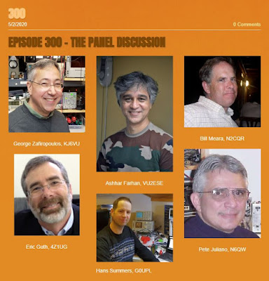
Presence (Absence?) and Direct Conversion Receivers (with wise comments from Farhan)

Hello Bill,
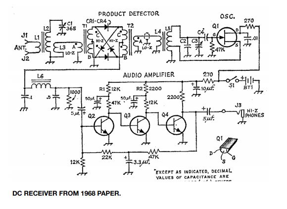
I was reading an online article by Wes Hayward, W7ZO from 1968 about the history of direct conversion receivers (http://w7zoi.net/dcrx68a.pdf) . It was linked in an email in qrptech. It recounts how he had first build a dc receiver with a single diode for the detector, and how microphonic it was, and dissatisfying an experience. This was in the early days of solid state devices, and so they were hard to come by. He describes meeting another ham engineer at work Dick Bingham, W7WKR who immediately recognized that what he needed was a diode ring mixer. The story goes on to describe their experiments, and success at this design.

They decided to write up the design for QST. I won’t bore you with the details…the article is well worth reading about how Wes mailed the radio and the design to ARRL, and how it ended up in the hands of a new person on their staff there, Doug DeMaw, W1CER (later W1FB.). Here is an excerpt from the article describing Doug’s reaction to the receiver:

This was the epiphany, the moment when Doug realized that solid-state technology had produce a new way to build a simple receiver. Doug tuned the receiver higher in the band and found some SSB. Again it was like nothing he had ever heard. It was as if the voice came from the same room. Doug used the term presence in his description.”

Here I present the earliest use, that I know of, of presence being used to describe a receiver. I have to say when I read it, I immediately thought of you guys, and decided to share.

Thanks for all you guys do.
dave /nt1u
———————————————————-
Bill replied:

Thanks Dave. Yea, that’s the 1968 article that launched the use of DC receivers. I had forgotten about DeMaw’s early use of “presence.”

Just to cause trouble, perhaps we should start commenting on “absence” i.e. “I dunno OM, I think your rig lacks a bit of absence in the mid-range… turn menu item 63b to ELEVEN!”
đŸ™‚
73 Bill
———————————————————-

Farhan wrote:

Mon, Aug 3 at 3:22 PM

When I got my license, my friend Anil SM0MFC was living in Hyderabad. He lent me his HW-8. I stringed up a 40 meter dipole with a lamp cord and worked with it. Somehow, the combination of the lamp cord length and the 40 meter inverted V made it resonate on 20 m as well. The HW-8 had a nominal antenna tuner and I worked pretty good DX.

Till date, it remains the best receiver that I have used for regular contacts. The only trouble it had was the the MC1496 was a nominal detector, it overloaded heavily with shortwave broadcast stations. There was an unnecessary RF amplifier in the front-end that they could have done without.

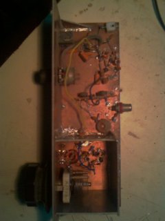
I made several direct conversion receivers, but never managed to hang on to any. This makes me want to build one, one of these evenings. I even have a KK7B R1 kit. but real men solder on without any PCBs or even circuit diagram!

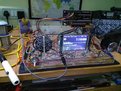
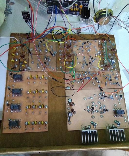
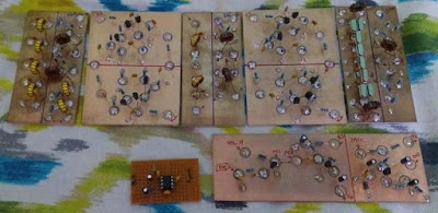
A 7/14/21 direct conversion radio that puts out 3 watts of power is what my ideal setup would be. I am not too bothered with the images on CW. I just tune them out in my head. Real soon now, at the moment, i am trying to finish a radio that has been in the works for years. Finally, I am making some headway.
-f
———————————————
Farhan of course is no slouch in the DC receiver area. Years ago he wrote a wonderful post about building a DC receiver with his cousin for her class project:

Included in this post was a passage that I included in my book SolderSmoke — Global Adventures in Wireless Electonics:
————————–
Why build a receiver?
Why do you want to build it? These are available at the Dubai Duty Free asked Harish, an old friend, when he spotted us struggling over the DC40 one evening. I didn’t have an answer to this question and considering the amount of work piled this quarter, it appeared to be a sensible thing to ask.

I think this question is answered by us all in different ways. My personal answer would be because we human beings are fundamentally tool builders. We have an opposable thumb that allows us to grip the soldering iron.
For an engineer (by the word ‘engineer’, I don’t just mean those who have a degree, but anyone who applies technical knowledge to build things) the act of building a receiver is a fundamental proof of her competence and capability. It is much easier to put out 1 watt signal than it is to receive a 1 watt signal.
A simple definition of a good receiver is that a good receiver consistently, clearly receives only the intended signal, such a definition hides a wide range of requirements. The receiver has to be sensitive enough to pick up the weakest signal imaginable (note: clearly), it has to be selective enough to eliminate other signals (only), it has to be stable enough (consistently).
For a ham or an engineer, building a usable receiver is a personal landmark. It establishes a personal competency to be able to understand the very fundamental operation of the radio and mastery over it.

——————–
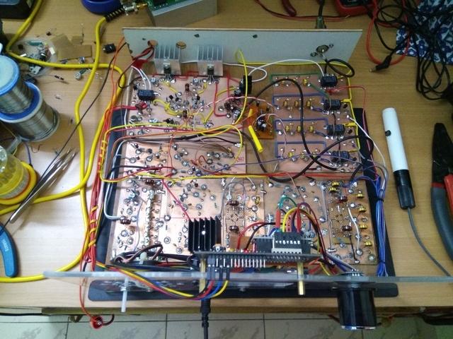
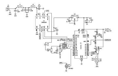
Bill: OM Ryan Flowers did a 5 part series on building the DC40. If you are want to build one, I suggest you use the schematics on Ryan’s site. There was an error in Farhan’s original schematic — Farhan corrected it but some of the incorrect schematics are still floating around the internet. Here is part one of Ryan’s series:
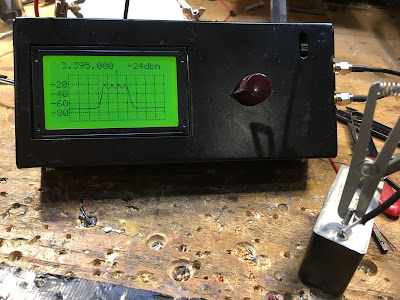
Farhan’s DC40

QSO Today — Episode 300 — Panel Discussion

Congratulations to Eric Guth, 4Z1UG for reaching episode #300 on his QSO Today podcast. To commemorate the event, Eric organized a panel discussion. It was a real pleasure and honor to participate.


Thanks again Eric!

Farhan’s New uBITX Version 6!

I’m currently reviving my “version 3” uBITX and putting it on CW. It sounds and works great, but when I saw this I realized that I am falling behind.

Farhan wrote:

Here is what it looks like :
And of course, yoiu can buy it on hfsignals.com. The shipping will happen from Tuesday onwards. We have a limited supply of the first 200 boards. The rest is for after christmas.

The most important thing about this revision is that the Radio circuitry is almost unchanged. We have incorporated the connectors on the PCBs. So, this kit needs none of the confusing soldering. You snap in the TFT Raduino onto the main board, plug the power and antenna from the back, snap on headphones, plug in the mic (supplied with the kit) and off you go!

It is offered in two kits now : The basic kit (150 USD) is without the box (like old times) but with a microphone and two acrylic templates for the front and back panels.
The Full kit (199 USD) has the box with speaker, mounting hardware etc. Both are described on the website.

Now, about the TFT display:

For those who are using the 16×2 display and you would like to upgrade, you will have to do three things:
1. Add a heatsink to the 7805 of the raduino
3. Grab the new Arduino sketch from https://github.com/afarhan/ubitxv6

Background :
I have been hacking away at adding a TFT display for the Arduino for sometime. Finally, I managed to do this with a really inexpensive 2.8 inch TFT display that uses a controller called the ILI9341. The display update is slow but, clever guy that I am, the display very usable. it uses the same pins that earlier connected to the 16×2 LCD display. This display is available everywhere for a few dollars.

_._,_._,_

VU3JVX’s Beautiful Homebrew Scratch-built uBITX

When Farhan announced that BITX40 Module boards would no longer be produced, my first thought was that it is, of course, still possible to homebrew a BITX. Anthony VU3JVX proves that in his wonderful description of his uBITX scratch-built homebrew project. Anthony obviously learned a lot — perhaps the most important lesson for new homebrewers is what Anthony did when he couldn’t get the receiver to work: HE TOOK A BREAK and went back after a few days. That is very important.


I also liked very much the fact that Anthony did what Farhan did when the receiver came to life — he stopped building the transmitter and just listened to the receiver that he had built. FB OM.

And three cheers for Anthony’s XYL — she was very wise to suggest that he take on a project like this when he found himself out of work.

Anthony VU3JVX wrote:


I would like to share my journey of building ubitx from scratch, I would also like to dedicate this to Farhan (hope he will read this sometime) as he has always motivated to homebrew stuff.

I got my license ‘VU3JVX’ on March 2017. Passing the exam and getting on HF bands is still two different things. Yes, I started to transmit to local VHF repeater with cheap Chinese Bafong radio, I believe the most economical way to start the ham operator experience. However, I knew that I am missing something since I was not able to operate on HF bands.Coincidentally I saw that bitx40 became available as kit from HF Signals during the same time. I was happy to try it and that’s how I made my first HF rig. Then I came to know about the BITX20 forum and joined the same, one of the best thing I did after buying bitx40. I have learned a lot from all the great people caring and sharing information. I will try to contribute whatever way possible from my side in coming days.

I was already thinking of building bitx40 for other band (because the way Farhan Sir has drawn the schematic it becomes so tempting for DIY) and then ubitx happened and it changed everything. I started studying the ubitx circuit and collecting all the required components, even ordered the exact toroid from W8DIZ website (during my good days and travel to US) but I was not having enough time to put things together on the bench as I am by profession a computer network & security engineer. I was not sure what to do next, during this time my XYL suggested me that why don’t I focus on something which I always wanted to do. And that’s how my journey started to build the ubitx from scratch.


Honestly, I was not sure if this was the right time to start this project. So I started to work on building the receiver segment of ubitx only. I had my challenges during this time and at one point I thought I made a wrong choice of building ubitx, instead I should had tried the bitx40 circuit first. I was almost on the verge to pack up and shelf the project because I was not able to hear anything from the receiver itself forget about building the transmitter. Then took a break for few days and then started troubleshooting each segment one by one. Finally I found it after reading through the bitx20 forum that my Q70 to be defective then I also came to know that is it better to replace it with audio type transistor 2sc945.
I believe during this process I have read most of the content on bitx20 forum. Some name which repeatedly comes to my mind are Raj (vu2zap), Allison, Jerry and thanks to all other hams out there. I had all the version schematics but started my work based on V5 and wanted to get the best out of all the version so I kept the build approach modular and laying them almost like the schematic for easy troubleshooting (you can see those pic on my qrz page).

Next challenge was trying to be too good student and follow everything the master said (pun intended). I made a cocktail of 12 Mhz with 11.059 Mhz crystal filter (Farhan Sir I believe the schematic is still showing X7 as 12 Mhz) and after changing the X7 to 11.059 Mhz I was able to see the radio signal making it through the crystal filter, then came the next hurdle of fine tuning the USB and LSB and fiddling with the software for the right value. After the receiver started working I took a break from building the radio and started enjoying the receiver and checking all bands. One evening I narrowly missed Farhan ji on air but anyway I would not have been able to communicate with him since my ubitx transmitter was not ready.
After that day I thought of building the ubitx transmitter soon. I was quiet confident about the transmitter build by this time and thought it should be straight forward. Logically yes it should had been that way but I was so wrong. Following all the recommendation from the forum about harmonic issue and how to avoid them I started building the BPF. Then I started to work on the PA section then came tuning the IRF510 current (I call it “Bell the cat moment”) luckily I never blew any IRF510. However, the output watt on 40 M was hardly 2-3 Watts and other higher band less than 1 Watt. I knew something was wrong with those MOSFET but out of circuit the test look normal. I had some other stock from different source even those performed the same. Played around with different PA transformer settings and checking/tracing the RF signal. Everything looked normal till IRF510. Chances of fake IRF510 is less (as debated on the forum) as it is not an expensive RF part like RD16HHF1. Now I was confused, I had some spare new RD16HHF1 which I got online, which I was not very hopeful thinking that it might be fake. I thought of giving it a try (pin layout configuration was easy for me as I have taken the island cutting approach on single side copper board).

Voila ! I got a whopping 10+ Watt 40M, 5W on 20, 10W on 17M, 10W on 15M, 5W on 12M and 10M. Yes there are lot of fake IRF510 out there. Now it was time to test the homebrew rig on air, checked in at evening into All India Net and got 59 report and the net controller thought I am using commercial rig. Finally during these difficult time in my personal life I was able to smile and sleep well that day. The icing on the cake was installing the Nextion 3.5 display (If I remember correctly this is single most expensive component in the radio and thankfully it is optional).

Does that mean everything is 100% with my home brew ubitx ? Nope, I am still trying to figure out the feedback issue from the speaker during transmit. I traced the issue and found the audio leaking from emitter of Q6. I would like to mention that I tried all the audio circuit and finally settle for TDA2822 circuit. However, the issue is still there during transmit so I have made the audio circuit offline during transmit, I know this will impact my CW listening while transmitting when I upgrade my license . I have exhausted all solutions from Bitx20 forum but still no luck. I would be happy is someone can point me to the right direction. I would be also happy to share any information related to my build or the software settings/tuning, yes I like programming especially ‘C’ so I am comfortable with Arduino programs. I am thinking of building another PA module with IRF510, I personally feel IRF510 (I got the original finally) has made the home brewing so interesting.

Anthony VU3JVX


Farhan Visits Northern Virginia and SolderSmoke HQ

Our good friend Farhan came to Northern Virginia last week for the 50th Anniversary Symposium of AMSAT. We were really delighted that he also came to SolderSmoke HQ. Elisa and I gave him a lightning tour of Washington DC (including a quick visit to The Air and Space museum) and then we headed back to the shack from some radio work.
In the picture above you can see my BITX-20 (that Farhan designed) off his right shoulder. Off his left shoulder you sits my ET-2 rig. I really wanted to show Farhan how well the N0WVA regen performs — he was impressed, especially when we started listening to SSB contacts. It was really amazing that we were doing this with just one J-310 FET. This was great fun. Farhan tells me that he will soon take up the “two transistor challenge.”
When he was here in 2017, I tried to demonstrate my version of Rick Campbell’s R2 Direct Conversion receiver. Unfortunately, when I tried to show off the “single signal” capability that is the whole purpose for this receiver, it was NOT producing a single signal output — you could hear the signal on both sides of zero beat. One of the small AF chokes I had used had gone open, knocking our one of the two DC receivers. This time I had the problem fixed and single signal reception was successfully demonstrated.
Farhan brought me two pieces of test gear that I have needed for a long time: A step attenuator and a two tone generator. Paired with his Antuino, these devices will bring about a big increase in capability on my bench.
It was really great to have Farhan in the shack. We had a great time talking about ham radio and homebrewing. Elisa and I both really enjoyed hearing from Farhan about his travels and about his life in India. We are all really lucky to be in the same hobby as Ashhar Farhan. Thanks for the visit Farhan.
Here is a quick video of Farhan tuning the BITX 20.

Antuino’s Cubesat Origins, and How it Works (with video)

In a series of e-mails to the BITX20.io group, Ashhar Farhan VU2ESE provided background information on the origins of his new “RF Lab in a Box’ — the Antuino. He also explained how the device performs the SWR meter, Power Meter and Scalar Network Analyzer functions.

Farhan’s Antuino Page: http://www.hfsignals.com/index.php/antuino/

Dec 27, 2018 to BITX.io

peeps,


while trying to measure the swr on the cubesats, i figured i couldnt use any of the analyzers i had access to. they were simply too big to be stuffed inside a 10 cm cube. my simple resistive bridge was too insensitive for any reasonable work. so, i sat down and made an antenna analyzer from a spare raduino.

the code is wobbly and just about enough to get my work done. it works on a superhet principle. this is not my clever idea, rahul had mentioned this approach taken by a russian builder. i havent seen the original design. it would be interesting if rahul or someone can point me in the right direction.

the code and a pdf of the circuit is on https://github.com/afarhan/antuino. i am attaching the circuit for the lazy bones.

have a great holiday and get some dx !!

– f

Dec 28 2018

Jerry,

first, thanks. there is substantially your code in there.

second, onto the circuit. it uses two clocks. not three. the third is a spare output. more on that later.

the circuit here uses a resistive return loss bridge. the clock 1 drives the bridge through the R22 to a low level of -10dbm. If the bridge is perfectly balanced (that is, the antenna, R21, R29, R16, all the four are the same ohms), then, there will be no RF developed across pins 3 and 4 of the ADE mixer. Under ideal match conditions, there is no RF across the R26. As the mismatch increases, so does the RF across R26.

We could directly detect the voltage across the R26 with a diode detector. This is quite a popular configuration with most of the simple resistive kind of SWR bridges (like the one designed by Dan Tayloe). This simplicity comes at a cost. The problem is that the detector responds to all the RF between the arms. For instance, if another ham down the block starts to transmit, that energy will show up across the R26 and you will get crazy SWR. I had that problem with broadcast FM showing up on my 7 MHz dipole! Even if there was no RFI from elsewhere, harmonics and spurs from your own transmission can show false readings.

Here is an example: a 7 MHz transmitter with a 14 Mhz harmonic that is 20 db down is connected to a 7 MHz dipole. The dipole is perfectly tuned to show 1:1 SWR, hence, it should show no RF across R26. However, as the antenna is reflecting back the 14 MHz energy, the 14 MHz shows up across the R26.

What’s the solution to get a clean dip?The solution is to substitute a simple detector like a diode detector with a simple receiver that is tuned exactly to the frequency that you want to measure the antenna at.

So, the ADE-1 mixer, Q2, Q1 together form a very simple superhet receiver with 25 MHz IF andCLK2 as the local oscillator. The RF at the IF is directly detected and converted to db range with the AD8307. This simple configuration makes this a very powerful instrument.

Here are things you can do with it:

1. Switch off the CLK1, now you have a receiver that can very accurately measure RF levels at any specific frequency in db range. For instance, you connected your transmitter with a suitable RF attenuator to P3, you can tune to various harmonics and measure them very accurately. If you inject a two tone signal into an amplifier, you could easily measure the IMD and IIP3.
2. With the CLK1 on, the instrument now measures the return loss. you can measure the SWR of an antenna, S11 parameters of an amplifier, filter, etc.
3. With CLK1 off, CLK 2 on, the CLK2 can now tune to the frequency tuned in by the receiver’s LO (CLK0). By connecting a device/filter between P3 and P4, you can sweep it to measure the gain, frequency reponse.
4. As the diode mixer (ADE-1) has harmonic response, a local oscillator at 135 MHz, will also convert a 430 MHz signal into 25 MHz IF (430 – (135 x 3)). This is possible because we are driving the diode mixer with a square wave from the Si5351 and the local oscillator at 135 MHz also has a 405 Mhz harmonic in it. Hence, the range of this instrument extends to UHF.

The ADE-1 mixer is quite similar to the ubitx mixers. You could even use ubitx kind of discrete version of a diode mixer, it doesn’t work too well beyond 50 MHz. The pins 4 and 3 of the ADE-1 are the primary winding of the RF-input side transformer. The documentation recommends that we must ground 4, but that is not essential. We need a differential drive between those two pins, that is what the bridge provides anyway.

73, f

jerry,

i built it so i could stuff it inside the cubesat to measure the antenna. an external spectrum analyzer and its cables were upsetting the RF model hence, i needed something that could read the return loss sitting inside the cubesat. then, i borrowed by daughter’s DSLR with a monsterous tele lens and sat 100 meters away to read the the LCD display as it swept through the range.
the analyzer was removed once we knew the correct dimensions and the actual payload went inside the bird.
– f

First Use of Farhan’s Antuino Scalar Network Analyzer

I was learning my way around Farhan’s new Antuino this morning. Very cool. I decided to start with the Scalar Network Analyzer. I’ve spent so much time measuring and plotting filter response curves BY HAND… the Antuino is an opportunity for me to move into the 21st Century.

In the picture you see the results. I was using a Heathkit SSB filter with the center frequency at 3.395 Mhz. The Antuino was set for that freq, with the screen range set at +/- 10. That means each division on the screen is 1 khz (right?). The Heath filter is advertised as being 2.1 khz wide at 6 db down. That pretty much matches what we see here.

You can see ripple in the filter passband. This is almost certainly the result of an impedance missmatch. It looks to me like the Antuino is set up with 50 ohm inputs and outputs. The Heath filter probably needs higher impedances to have a smooth passband. I will try later to set it up for a smooth passband.

It is easy to see how useful this device will be. Thanks Farhan!

More on the Antuino here:

Antuino: Farhan’s Compact RF Lab In-a-Box

I now have Farhan’s latest invention, the Antuino. Pete will have his shortly. Very cool. SWR meter and antenna analyzer, power meter and scalar network analyzer all in one box. I put an old-school knob on the rotary encoder — it seemed like the right thing to do. Soon I will be able to find out if my rigs have spurs or are somehow non-compliant. I’m sure Farhan’s “RF Lab in a box” will be an important addition to my test gear arsenal. We will be talking about this in upcoming podcast episodes.

Mike N2HTT did a nice write up of the new device:

https://n2htt.radio/2019/05/26/hello-antuino/

And here is the info from the htsigs.com page:

http://www.hfsignals.com/index.php/antuino/

Thanks Farhan!

Circuit for Farhan’s Satellite — Arduino in SPACE

Farhan sent me the schematic of the AISAT amateur digital satellite that went into orbit on April 1, 2019 from India. He notes that the circuitry is very simple. Indeed, it reminds me of the very simple but effective circuitry we saw in satellites in the early days of the space age. Beautiful simplicity, with an Arduino on-board. And it is great to see that Farhan did not forget the low pass filter. FB OM.

Packets from Farhan’s Space Ship

Farhan’s AISAT flew over this morning. Using HD-SDR software, an RTL-SDR Dongle, and my Dominican Republic refrig tubing quad I was able to capture some the packets. Above you can see one of them, floating like a flying saucer in the waterfall. Pretty amazing that that signal came from a machine put in space by our friend Farhan.

Congratulations to Farhan on New Amateur Satellite Launched 1 April

This is not an April 1 trick. Farhan and Exseed Sat have put another bird in orbit.
Details here:
http://amsatindia.org/

This site in Argentina gives pass information:
http://amsat.org.ar/pass?satx=aisa1

I will be listening tonight!

Congratulations Farhan!

More info:


HNY (Happy New Year), SKN (Straight Key Night) 2019, and an HT-37 with “presence” — even on CW

I got the HT-37 working just a few days before the New Year’s Eve/New Year’s Day Straight Key Night event. Looking at my older blog posts, I now see that the problems first surfaced in LAST YEAR’s SKN. Wow, it took me a long time to get to that problem. But I’m glad I fixed it in time for SKN.

For SKN I used the VU3XVR straight key from India that Farhan gave to me. See the picture above.


I started out on 80 meters on New Year’s eve. I rarely operate on that band — I thought it would be a good change of pace. Here is who I contacted on 80 CW:

In the warm-up period before the official start of SKN I worked John KU4AF. John was running a homebrew tube transmitter and a REGEN receiver. Respect, my friends. RESPECT!

N9EP Ed near Chicago was on a K3.

VE9XX Don was on a KX3.

NJ8D Tom in Ohio.

K4IA, Buck, down the road in Fredricksburg Va. Buck was running a Drake TR4C with a Begali key. FB Buck. He mentioned that he had had a Drake 2B — he said he regrets selling it. Indeed.

VE9WW Bill in Moncton NB. On a straight key.

AA8MI Gene (gosh, that name really sings in CW — try it!) in Ohio. Gene was running 5 watts from a K3. This added a needed QRP element to the festivities. Thanks Gene.

AI4SV Jack in Rockville Md. OH MY GOD! NOW I REALIZE WHO THIS WAS! Jack! Jack of Antanarivo Madagsascar! And now I understand what he said to me. He said in CW that my HT-37 has “Lots of presence.” Huh? What? I couldn’t figure out what he was talking about, but now I realize that he was joking about all our discussions mocking the poor audiophiles. Well, thanks Jack. I’m glad the rig has presence, EVEN ON CW! THIS QSO GETS MY VOTE FOR BEST SKN QSO.

I also listened for a while to W3GMS. His signal had a lot of character and personality. He was telling the other fellow that he suspected this was the result of a soft voltage regulator tube in his DX-60. I think he was also using a Drake 2-B. I didn’t get a chance to talk to Howard, but I’m sure it would have been fun.

On New Year’s morning I switched bands. First to 40 where I worked Greg NM2L near Atlanta. He said he fingers and wrist were out of condition, but I told him his fist was FB.

Then I went to 20 CW where I worked a bit of DX. First David F8CRS then Bert F6HKA. The contact with Bert reminded me of the charms of DX contacts using CW. “VY GM DR OM.” It was nice.

N7AQQ Mike in Montana.

So it was a good SKN for me. Working the French stations reminded me of the allure of listening to CW coming in from far away, and from a foreign culture. And it was great to hear from AI4SV that my HT-37 has “presence” even on CW.

73 and HNY to all.

Launch Day! Godspeed Exseed! 1:31 pm Eastern time. Video links here.

Farhan posted this message and the above video to Facebook today (I have the video cued up to around the 5 minute point):

We are all set for the launch of ExseedSat… There are two tiny switches at the bottom of the satellite that keep the satellite switched off while it stays in it’s container. Once the satellite is ejected, the switches are released and the satellite wakes up.
There are 36 satellites on this launch, some belong to close friends in the satellite fraternity. We wait for all the satellites to drift out and after 45 minutes, the antennas are depolyed and we will start beeping signals home.
Here is a test of that process. You can skip to the fifth minute to watch the antenna depoly .


I really like the tape measure antenna. This recalls the earliest OSCAR satellites. And let’s not forget that OSCAR 1 also launched from Vandenberg. So there a lot of good tradition flying with Farhan’s bird.

Press reports indicate a launch time of 1:31 pm Eastern time today. I think you can watch it live through the video window below. Or try this link:

https://www.youtube.com/watch?v=Wq8kS6UoOrQ

Cubesat Launch Now Scheduled for Sunday Morning (California time)


Here is an update from the San Luis Obispo News:
It kind of makes you wish you were out there…


https://spacenews.com/dedicated-rideshare-falcon-9-launch-raises-satellite-tracking-concerns/

https://www.theverge.com/2018/12/1/18114894/spacex-falcon-9-reusability-sso-a-mission-rideshare-satellites

Totally Absurd — Farhan Being Questioned in a Police Station

I walked into the shack this morning hoping to read good news about the InSight landing and the impending launch of Farhan’s satellite, but instead I found this message from Farhan in a police station. This is really absurd and disheartening. Someone (not Farhan!) altered the Indian flag and put it into an image of Farhan’s CubeSat. So with 24 hours to go before the launch, our friend Farhan finds himself in a police station.

Stay strong Farhan! You have a lot of support around the world.

The Max Valier Satellite Flies Over, Sending CW

I understand the launch of Farhan’s CubeSat has been delayed a few days. That’s the way it works in the rocket launch biz –patience is required. In the meantime, I’ve been practicing with my receive system. Today at 1000 local the Max Valier satellite flew to my west. It rose 78 degrees above my horizon to the W NW. I left my three element quad pointed in that direction and waited for the satellite (which had been launched from India) to fly through its pattern.

The CW beacon was quite strong, very visible and audible through my RTL-SDR dongle and HD-SDR software. You can see it and hear it in the video above. There is something quite charming about this very personal Morse message coming down from orbit and then passing through all that digital technology.

More info on the satellite:


“Max Valier Sat” is an amateur satellite built in cooperation by:

  • “Max Valier” High School in Bolzano/Bozen (Italy)
  • OHB System AG from Bremen (Germany)
  • Max Planck Institute for Extraterrestrial Physics from Garching (Germany)
Its main payload is an X-Ray telescope devised and made by MPE. Data generated by this detector will be transmitted, together with housekeeping data, over an amateur radio link with frequency 145.860 MHz.
A second payload is an amateur radio beacon transmitting a message in Continuous Wave. The beacon’s frequency is 145.960 MHz
“Max Valier Satellite” was launched by the Indian Rocket PSLV-C38 on June 23, 2017 at 9:29 am IST (05:59 am CET) from Satish Dhawan Space Centre.
More tech details:
Regarding the CW beacon:

Beacon by Holger Eckardt DF2FQ:

  • Transmit frequency is 145,960 MHz (IARU and ITU coordinated).
  • Modulation is CW:
    • Duration of one dot is 114 ms.
    • Duration of one dash is 342 ms.
    • Interval between words is 1881 ms.
    • Interval between repetitions of the message is 6000 ms.
  • The beacon transmits Max Valier Sat’s call sign and a greeting message.
  • Transmitting power is 500 mW.


And who was Max Valier? Quite an interesting fellow:

Max Valier in his Rocket Car in 1930