Thank God for the Wayback machine. For a moment I feared that this article about Farhan’s DC-40 receiver had been lost. (Phonestack is now some Vietnamese vendor. ) But the WayBack Machine archive came through for us.
I really like Farhan’s blow-by-blow description of the build. There are raw emotions here: He speaks of his hatred of LM-386s, and of how he thought of using the copper clad board as a projectile. His niece wonders about the possibility of evil spirits in the receiver. The battle against AM breakthrough is very familiar. (I like the RF choke idea.) You won’t find candor like this in QST or QEX.
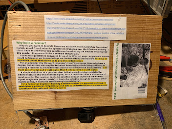
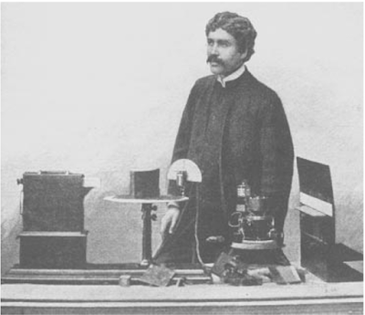
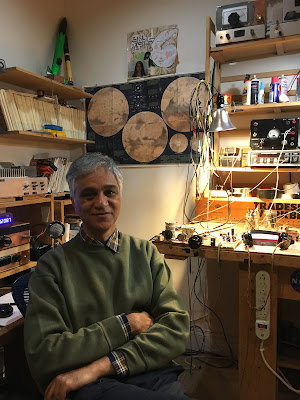
Farhan’s DC-40 project was one of the inspirations for our high school effort. In fact, when we first went to the school, I left behind a direct conversion receiver that I had built. Taped onto the bottom of the receiver was a quote from the DC-40 article and a picture of the Wizard of Hyderabad. (See above, and click on the picture for a better look).
This week we will inject some more Farhan-ismo into our receiver. The time has come to build the mixer. Like Farhan, we will go with the diode ring. Winding the transformers would be very time consuming. I remembered that on his visit, Farhan had left me a box of trifilar toroids wound by the seamstresses of Hyderabad using FT37-43 cores. We will uses these in our build. They will add a lot of soul to the new machine.
A while back I posted the re-mastered version of the excellent “Secret Live of Machines” episode on radio. Among other amazing things, Tim and Rex build a spark radio transmitter and a receiver that uses a coherer and a tapper. They even set up a demonstration and sent signals from the pier to the shore. Very cool.
I shared this with George WB5OYP of the Vienna Wireless Society because he had been looking carefully at the gear that Marconi allegedly used to make that first transatlantic contact. George wondered if Marconi could have really done this with a coherer as his detector; he was — for good reason — skeptical. Could a glass tube filled with metal filings really detect radio waves sent from across the mighty Atlantic?
Marconi claimed that he did it with a coherer as the detector:
On December 12, 1901, Marconi attempted to send the first radio signals across the Atlantic Ocean, in spite of predictions that the radio waves would be lost as the earth curved over that long distance. He set up a specially designed wireless receiver in Newfoundland, Canada, using a coherer (a glass tube filled with iron filings) to conduct radio waves, and balloons to lift the antenna as high as possible. The signals were sent in Morse code from Poldhu, Cornwall, in England. Marconi later wrote about the experience:
“Shortly before midday I placed the single earphone to my ear and started listening. The receiver on the table before me was very crude — a few coils and condensers and a coherer — no valves, no amplifiers, not even a crystal. But I was at last on the point of putting the correctness of all my beliefs to test. The answer came at 12: 30 when I heard, faintly but distinctly, pip-pip-pip. I handed the phone to Kemp: “Can you hear anything?” I asked. “Yes,” he said. “The letter S.” He could hear it. I knew then that all my anticipations had been justified. The electric waves sent out into space from Poldhu had traversed the Atlantic — the distance, enormous as it seemed then, of 1,700 miles — unimpeded by the curvature of the earth. The result meant much more to me than the mere successful realization of an experiment. As Sir Oliver Lodge has stated, it was an epoch in history. I now felt for the first time absolutely certain that the day would come when mankind would be able to send messages without wires not only across the Atlantic but between the farthermost ends of the earth.”
I mentioned this in SolderSmoke Podcast #242. This resulted in a very interesting message from Steve AB4I:
The reason that I am writing is to comment on the coherer and Marconi’s transatlantic test. One of my research interests in my doctoral studies was the development and evolution of early radio detectors. Marconi did not use a coherer for the successful transatlantic tests, but secretly used a detector and telephone receiver that had been invented by the Indian polymath Jagadish Chandra Bose of Calcutta. Bose’s iron-mercury-iron detector was sensitive to a wide range of wavelengths and he used the detector in his 60-GHz millimeter wave and experiments. Bose presented his results to the Royal Society in London in 1899 and his paper was published in the Proceedings of the Royal Society the same year. Marconi came by the mysterious mercury coherer detector through a friend in the Italian Navy who constructed the device from Bose’s paper in the Proceedings in an effort to improve the performance of the Marconi equipment aboard . The Bose detector was superior to anything that Marconi had and was key to the success of the transatlantic tests and for Marconi’s subsequent successes. Marconi then filed a patent for the detector in his own name in 1902, even though it was not his invention.
A lot of nasty business went on in the early days of wireless. The scandal around the “Italian Navy coherer” raged for years, but eventually the role of Bose was revealed. The popular view of Marconi as radio inventor extraordinaire is idealistic, because he did not actually invent anything, but he was very good at dragging laboratory hardware into the real world to serve practical ends. In every case, crucial parts of Marconi’s patents were stolen or copied from other sources and successfully defended through aggressive litigation, deep financial backing, and extensive public relations through advertising and newspaper interviews. Marconi absolutely deserves recognition for his successes in the development of practical wireless communications although he is not noted for his ethics. Marconi’s reputation is a bit tarnished nowadays, but that of Jagadish Chandra Bose has blossomed and he is now acknowledged for his epochal work that was fully a half-century before his time.
As for the coherer, we still do not have a full understanding of how the thing actually works. The cohesion effect of small particles clumping together in the presence of a static charge has been known from antiquity as evidenced by dust bunnies under beds through the ages. There were coherer-like lightning arrestors used on telegraph lines just after the American Civil War and in 1879 David Hughes found that a carbon microphone with loose contacts could detect arcing in nearby equipment and from considerable distances too. He was told that the phenomenon was nothing new and he just missed the discovery of radio waves. Thanks to some monumentally bad advice we now speak of Hertzian Waves instead of Hughian Waves. Branly made a detailed study of resistance changes in metal particles and is generally acknowledged as the inventor of the coherer detector. Oliver Lodge coined the name ‘coherer’ and demonstrated the detection of Hertzian waves in 1894 a few months after Hertz’s death. Lodge wrote a tribute to Hertz, which was to inspire the young Marconi to begin his own experiments with Hertzian waves.
Here are the key passages: One improvement invented by Bose in 1899 was the iron-mercury-iron coherer, with a pool of mercury in a small metal cup. A film of insulating oil covered the mercury, and an iron disc penetrated the oil but did not make contact with the liquid mercury. RF energy would break down the insulating oil and conduct, with the advantage of not needing a decoherer to reset the system.
Bose’s improved coherer design would miraculously appear in Marconi’s transatlantic wireless receiver two years later. The circumstances are somewhat shady – Marconi’s story about how he came up with the design varied over time, and there were reports that Bose’s circuit designs were stolen from a London hotel room while he was presenting his work. In any case, Bose was not interested in commercializing his invention, which Marconi would go on to patent himself.
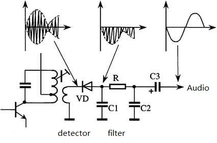
Most of us grew up with the above diagram of how a receiver detects (demodulates) an AM signal. Here is how they say it works:
— Because of the way the sidebands and the carrier in the transmitted signal interact, we end up with a signal whose “envelope” matches the frequency of modulation. And we just need one side of the envelope.
— We used a simple diode to rectify the incoming signal.
— A simple filter gets rid of the RF.
— We pass the resulting signal through a capacitor and we get audio, which we listen to.
REASONS FOR SCEPTICISM
But recently, a member of my local radio club has questioned this explanation of AM detection. He maintained that “envelope detection” is not real, and that was actually happening was “square law” mixing. I guess there are reasons for skepticism about the envelope detection explanation: The envelope detection explanation does seem very (perhaps overly) simple. This does sound a bit like the kind of “dumbed down” explanation that is sometimes used to explain complex topics (like mixing). Envelope detection does seem consistent with the incorrect insistence from early AMers that “sidebands don’t exist.” (Of course, they do exist.) All the other detectors we use are really just mixers. We mix a local oscillator the incoming signal to produce audio. Envelope detection (as described in the diagram above) seems oddly different.
Denial of envelope detection can even be found in the ARRL handbook: On page 15.9 of the 2002 edition we find this: “That a diode demodulates an AM signal by allowing its carrier to multiply with its sidebands may jar those long accustomed to seeing diode detection ascribed merely to ‘rectification.’ But a diode is certainly non-linear. It passes current only in one direction and its output is (within limits) proportional to the square of its input voltage. These non-linearities allow it to multiply.”
ISN’T THIS REALLY JUST MIXING, WITH THE CARRIER AS THE LO?
It is, I think, tempting to say — as the ARRL and my fellow club member do — that what really happens is that the AM signal’s carrier becomes the substitute for the VFO signal in other mixers. Using the non-linearity of the square law portion of the diode’s characteristic curve, the sidebands mix with the carrier and — voila! — get audio. In this view there is no need for the rectification-based explanation provided above.
But I don’t think this “diode as a mixer, not a rectifier” explanation works:
In all of the mixers we work with, the LO (or VFO or PTO) does one of two things:
— In non-switching mixers it moves the amplifier up and down along the non-linear characteristic curve of the device. This means the operating point of the device is changing as the LO moves through its cycle. A much weaker RF signal then moves through the device, facing a shifting operating point whose shift is set by the LO. This produces the complex repeating periodic wave that contains the sum and difference frequencies.
— In a switching mixer, the device that passes the RF is turned on and off. This is extreme non-linearity. But here is the key: The device is being turned on and off AT THE FREQUENCY OF THE LO. The LO is turning it on and off. The RF is being chopped up at the rate of the LO. This is what produces the complex repeating wave that contains the sum and difference frequencies.
Neither of these things happen in the diode we are discussing. If you try to look at the diode as a non-switching mixer, well, the operating point would be set not by the carrier serving as the LO but by the envelope consisting of the carrier and the sidebands. And if you try to look at is as a switching mixer you see that the switching is being controlled not by the LO but by the envelope formed by the carrier and the sidebands.
Also, this “diode as a mixer” explanation would require the diode to be non-linear. That is the key requirement for mixing. I suppose you could make a good case for the non-linearity of solid state diodes, but the old vacuum tube diodes were quite linear. The rectifying diode mixer model goes back to vacuum tube days. The “diode as rectifier” model worked then. With tubes operating on the linear portion of the curve, the diodes were not — could not — have been working as mixers. We have just substituted solid state diodes for the tubes. The increased non-linearity of the solid state diodes does introduce more distortion, but the “detection by rectification” explanation remains valid.
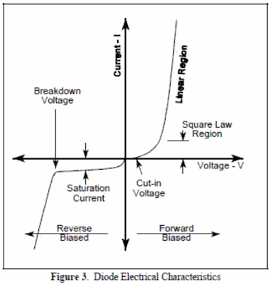
Even in the “square law” region (see diagram below) an AM signal would not really be mixed in the same way as signals are mixed in a product detector. Even in the square law region, the diode would be responding to the envelope. Indeed, the Amateur Radio Encyclopedia defines “Square Law Detector” as “a form of envelope detector.” And even in the square law region, the incoming signal would be rectified. It would be moving above and below zero, and only one side of this waveform would be making it through the diode. Indeed the crystal radio experts discuss “rectification in the square law region” (http://www.crystal-radio.eu/endiodes.htm ) So even in the square law region, this diode is a rectifying envelope detector.
Here is what I think is the best proof that the “envelope detection” explanation is real: In this video, we see someone build an envelope detector in a simulator. Watch as he then traces the signals as they move through the diode, the RC filter, and the coupling capacitor. He goes through it cycle-by-cycle. You can clearly see how the rectification of the AM leads to envelope detection.
The rectifying envelope detection model goes way back in radio history, back to when authors did not shy away from complex technical explanations. Terman knew how mixers worked, and his 1943 “Radio Engineers Handbook” went to 1019 pages. Terman presented it as a rectification-based detection of the envelope. I think envelope detection is real, and that Dr. Terman was right.
————————————–
Some links that might help:
Analog Devices has a very good, rigorous site showing how envelope detectors work:
The crystal radio guys have a good take on square law detection (note, they just see it as rectification, but on a lower, more parabolic portion of the curve): http://www.crystal-radio.eu/endiodes.htm
There is so much radio goodness in this rig and in the blog post that describes it. Farhan’s blog post will keep us busy for a long time. There is much to learn there. But perhaps even more important is his larger view of the role of analog circuitry in ham radio. Here are a couple of excerpts from his introduction:
Here is the memo : The analog never died. The world is analog all the way, until you descend into Quantum madness. The antennas are analog, Maxwell died a content, analog man. Our radios, ultimately, are analog machines and we are all analog beasts too. Amateur Radio technology has evolved into the digital domain. However, it has only made it easier for us to do analog with computers to simulate and print our circuits. So, it’s time to bid good bye to our Arduinos and Raspberry Pis and build an Analog Radio for ourselves. So let’s see what we can achieve in hindsight, a return to our native land and a rethink of our approaches.The radio is called Daylight Again, a nod to being back at the FDIM in 2022 after a gap of two years. It is named after the Crosby, Stills, Nash and Young’s song that had been humming all the time while put this radio together, emerging after 2 years of lockdown. This radio that took two days to come together, no actually two years! That’s: parts of it got built and stowed away, thoughts were struck in the shower, questions popped up during early morning cycle rides and notes and circuits were scribbled in the notebook. I must take the first of many diversion here: I hope you all maintain a notebook. Write down the date and whatever you thought or did on the bench and the result. Nothing is trivial enough to leave out. Wisdom comes to those who write notes. I started to build this on Saturday the 14th May and I checked into the local SSB net on Monday morning, the 16th May 2022.
AND
Having clean VFO is the most important way of increasing the dynamic range of your radio. A free running JEFT VFO that has sufficient power and a good Q components, will be unmatched by any synthesized or direct sampling radios. The math is all on the side of the free running VFO. We are talking -150 db/Hz at 10 KHz spacing, by comparison the Si5351 is -125 db/Hz, it is 300 times worse.
That is just part of the intro. We should all study the rest of Farhan’s blog post very carefully and incorporate the wisdom into our new rigs:
OM Basanta VU2NIL built a very nice antenna tuner using homebrew variable capacitors (above). After seeing this, I feel unworthy — I used FACTORY-MADE variable capacitors. I feel like such an appliance operator. I hang my head in shame.
The Radio Gods seem to be steering us toward Double Sideband. A few days ago I got an e-mail from Alain F4IET. We had him on the SolderSmoke blog two years ago, talking about his French backyard pandemic Field Day. His recent e-mail reminded me of his very fine homebrew DSB transmitter, which is his only rig and with which he has worked the world.
The rig is named for the fellow — Robert F6EUZ — who is Alain’s teacher from the local radio club.
Alain’s rig was shown to the world in the G-QRP club’s Winter 2020 issue of SPRAT (SPRAT 185). Once again, let me note: If you are not subscribing to SPRAT, you are just WRONG. Join G-QRP and start receiving SPRAT: http://www.gqrp.com/join.htm
Alain gives some nice shout-outs to Pete N6QW, Charlie ZL2CTM, and Basanta VU2NIL, all of whom provided advice and counsel on this project. So think about it: the Master Robert rig was built in France under the guidance of a French Elmer, with advice from hams in the U.S., New Zealand, and India, and was featured in journal of the British QRP club. That, my friends is the International Brotherhood at its best.
As I read about Alain’s rig, I found myself thinking about the Direct Conversion receiver projects underway around the world. The Vienna Wireless Society’s Maker Group, is, for example, building a simple DC receiver. It would be relatively easy to pair up a rig like the Master Robert with a DC receiver (the VFO could be the only stage common to both transmit and receive) to make a simple phone transceiver. That kind of rig was my first phone transceiver. Alain reports that he is currently working on a second version of the Master Robert. It will be a transmitter-receiver (TRX) and will be used in SOTA operations.
I especially liked his comment about how the other phone stations never knew he was on DSB: http://www.f4iet.fr/mdwiki/#!dsb.md I had similar experiences out in the Azores with my DSB rigs.
Bob Crane W8SX — our correspondent in Dayton/Xenia — once again collected interview with FDIM presenters. Thanks Bob! Here is his talk with our friend Farhan:
This is a really nice look at hobbies and their role in life. It is very relevant to discussions of The Knack.
Many of the quotes resonate with me, especially those about how hobbies — in our case ham radio — provide an important source of enthusiasm. I remember an old timer in Rome telling me that at age 85, he jumped out of bed each morning, heading to the radio shack with enthusiasm.
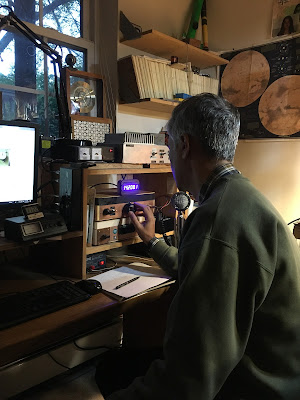
I’d add that ham radio adds elements of permanence and continuity in our lives. For many of us, we’ve been working on radios since our early teens. I have in my shack gear that I’ve had for almost 50 years! Amidst the vicissitudes of life, it is really nice to have things with this kind of permanence.
Thanks to Atanu Dasgupta of the Lamakaan Amateur Radio Club of Hyderabad for alerting me to this article. OM Atanu wrote:
My friends, acquaintances and members from my extended family often ask me how I spend my time and keep myself busy throughout the day. When I say I pursue a hobby called Amateur Radio (Ham Radio) and I spend more than 8-10 hours in a day for that purpose, I don’t find many takers. Many of them feel that I must be earning handsomely by devoting my energy and time as seriously as pursuing a regular work-from-home regime for some corporate entity. Sometimes even my domestic help express doubts, albeit in a decent manner, about my devotion to something in life without any financial gain and expect a wage-hike for them against my ‘extra earning’. After all how can a hobby (pastime) can keep someone so engrossed physically, mentally – on the computer, over thick books/ magazines , on the work table at the radio shack, on the floor for some odd metal works, on the rooftop with antennas, over the Radio-on-air, over phone etc – without some pecuniary benefits? Recently a brilliant essay by Himani Datar on ‘hobby’ in the Hindu Magazine (https://www.thehindu.com/…/hobby-high/article65375392.ece ) has been very impressive and appears to be a savior to all concerned like me. The essay brings out all in favour of all hobbies and hobbyists and I feel more confident now about my course of engagement on a long-term basis.
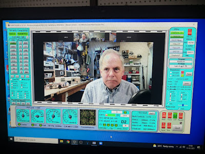
Farhan VU2ESE kindly invited us to talk to his Lamakaan Amateur Radio Club. They did a simulcast through the QO-100 Geostationary Satellite. This picture shows N2CQR being beamed into India from 22,500 miles. Note the ET-2 and the Mythbuster on the bench. This was a lot of fun. Thanks Farhan!
This is really beautiful. Radraksha Vegad (Pargrahi) from India built a discrete component version of the venerable 555 timer chip. He built it on wooden blocks. This leads to the kind of understanding that even Jean Shepherd would have admired. No longer is the 555 a little mysterious black box. No, Pargrahi shows us how it works.
I know we could do something similar with the NE602 or the LM386. But probably not with an Arduino microcontroller or an Si5351. And that says something about understanding and complexity.
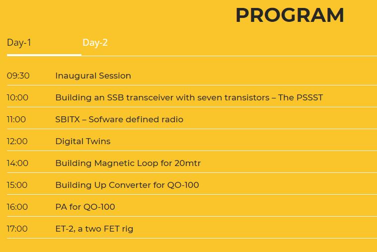
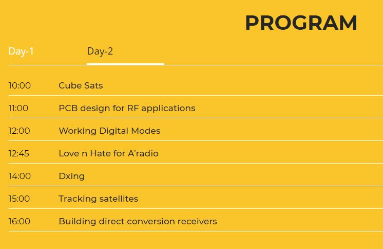
The Lamakaan Amateur Radio Club’s annual convention begins today in Hyderabad, India. This is Farhan’s club so it is sure to be a great event. Presentations are being live streamed on YouTube and on the QO100 geostationary satellite.
Pete N6QW will be the first presenter and will talk about his new PSSST Rig. He will be speaking at 0430 UTC Saturday 11 December. That is 11:30 pm on Friday, December 10 on the East Coast of North America.
I will be speaking at 1130 UTC on Sunday December 12. That is 0630 Saturday 11 December EST. I’ll be talking about the Mythbuster rig and about the ET-2.
I don’t know how we might be able to watch or listen via the QO100 satellite. The U.S. is not in the footprint of this bird. But there is a good WEBSDR receiver run by BATC and AMSAT DL: https://eshail.batc.org.uk/
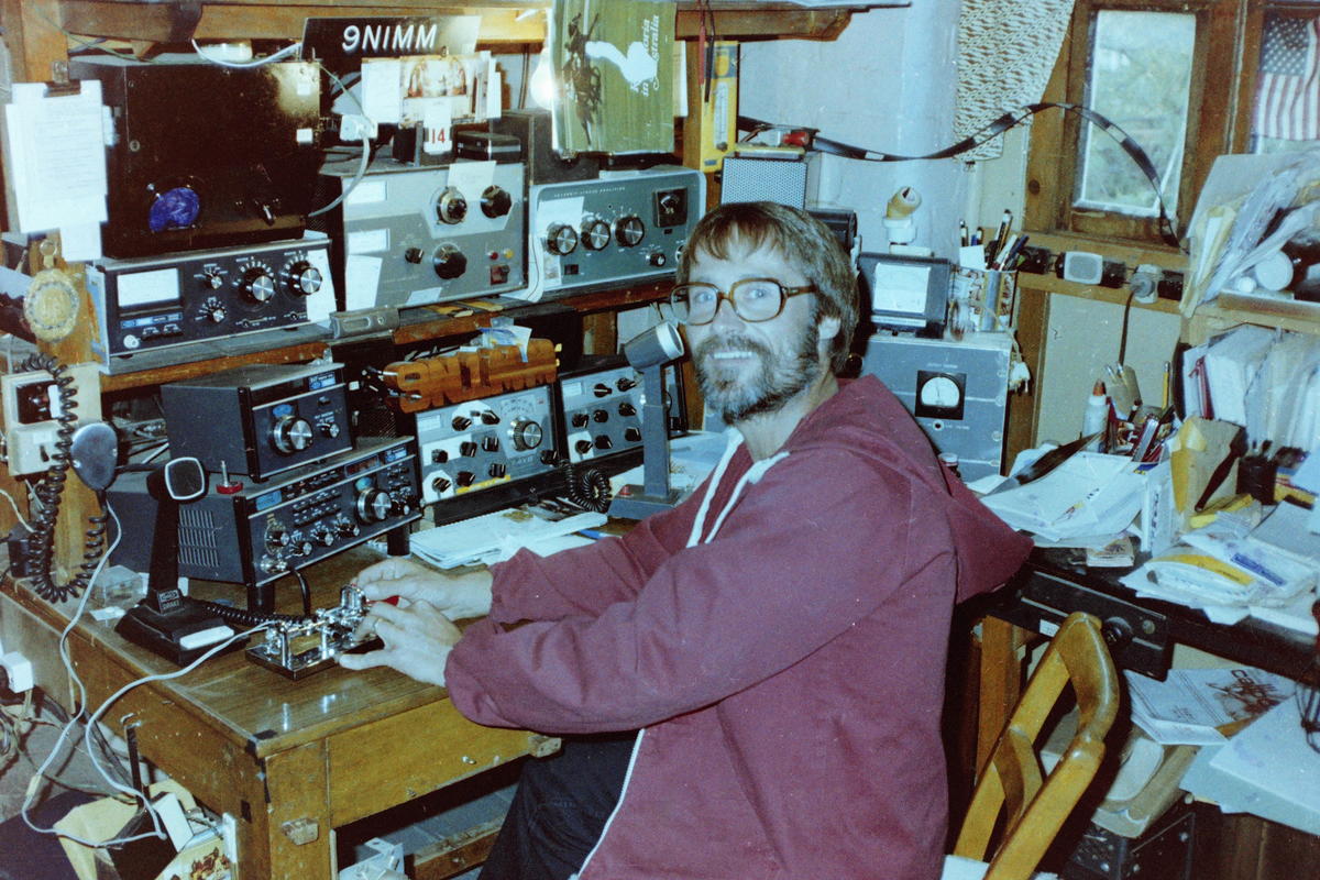
Jerry KI4IO is such an amazing homebrewer that he has been dubbed “The Wizard of Warrenton.” The picture above shows Jerry during the early 1980s in the shack of Father Moran 9N1MM in Nepal. Jerry was also in India. (I previously posted the info on Jerry’s time in India and Nepal, but I didn’t have this picture. The picture makes it worthwhile to post the story again.) From Jerry’s QRZ.com page:
——————————-
While in India I was licensed at VU2LHO and worked a lot of US hams with a 135′ flat-top and open-wire feed. I had the antenna strung between two bamboo towers atop the embassy housing 2nd-story roof-top. I also put up a 3/8 wave vertical on the roof for 10 meters. That little antenna had 110 radials stapled into the roof screen and worked very well! The rig was a HW-101. I was in Kathmandu, Nepal from early 1980 to late 1982. I could not obtain a license there, but became good friends with Father Moran, 9N1MM, and would often spend time up at his place putting his Drake station on CW. Pretty cool being real DX! Back in the states in late 1982.
Here I am at one of my many visits to Father Moran’s shack.
I got in touch with Jerry because Pete Eaton reminded me that Jerry had homebrewed a discrete transistor version of the NE602 Gilbert Cell Mixer, a device that I am very interested in. Nick G8INE also built one.
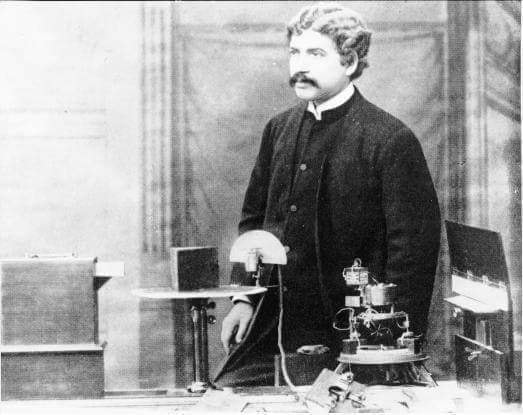
Acharya Sir Jagadish Chandra Bose, was a Bengali polymath, physicist, biologist, botanist, archaeologist, as well as an early writer of science fiction. He pioneered the investigation of radio and microwave optics, made very significant contributions to plant science, and laid the foundations of experimental science in the Indian subcontinent. IEEE named him one of the fathers of radio science. He is also considered the father of Bengali science fiction. He also invented the crescograph.
Born in Bikrampur (present day Munshiganj District near Dhaka in Bangladesh) during the British Raj, Bose graduated from St. Xavier’s College, Calcutta. He then went to the University of London to study medicine, but could not pursue studies in medicine due to health problems. Instead, he conducted his research with the Nobel Laureate Lord Rayleigh at Cambridge and returned to India. He then joined the Presidency College of University of Calcutta as a Professor of Physics. There, despite racial discrimination and a lack of funding and equipment, Bose carried on his scientific research. He made remarkable progress in his research of remote wireless signaling and was the first to use semiconductor junctions to detect radio signals. However, instead of trying to gain commercial benefit from this invention, Bose made his inventions public in order to allow others to further develop his research.
Bose subsequently made a number of pioneering discoveries in plant physiology. He used his own invention, the crescograph, to measure plant response to various stimuli, and thereby scientifically proved parallelism between animal and plant tissues. Although Bose filed for a patent for one of his inventions due to peer pressure, his reluctance to any form of patenting was well known. To facilitate his research, he constructed automatic recorders capable of registering extremely slight movements; these instruments produced some striking results, such as Bose’s demonstration of an apparent power of feeling in plants, exemplified by the quivering of injured plants. His books include Response in the Living and Non-Living (1902) and The Nervous Mechanism of Plants (1926).
……Bose’s education started in a vernacular school, because his father believed that one must know one’s own mother tongue before beginning English, and that one should know also one’s own people.
Speaking at the Bikrampur Conference in 1915, Bose said:
“At that time, sending children to English schools was an aristocratic status symbol. In the vernacular school, to which I was sent, the son of the Muslim attendant of my father sat on my right side, and the son of a fisherman sat on my left. They were my playmates. I listened spellbound to their stories of birds, animals and aquatic creatures. Perhaps these stories created in my mind a keen interest in investigating the workings of Nature. When I returned home from school accompanied by my school fellows, my mother welcomed and fed all of us without discrimination. Although she was an orthodox old-fashioned lady, she never considered herself guilty of impiety by treating these ‘untouchables’ as her own children. It was because of my childhood friendship with them that I could never feel that there were ‘creatures’ who might be labelled ‘low-caste’. I never realised that there existed a ‘problem’ common to the two communities, Hindus and Muslims.”
The presentation starts at about the 4 minute point.
I think if I were only allowed to watch one YouTube video in the next year, I’d make it this one.
In this amazing RSGB video, Ashhar Farhan VU2ESE takes us back to his earliest days as a radio amateur. He tells us about his very early desire to build radios, his early projects, and his personal evolution as a designer and builder, from a simple DC receiver, to the BITX, the Minima, the uBITX and now the hybrid HDR/SDR sBITX.
There is a lot of homebrew wisdom and tribal knowledge in this video. And we learn so many hitherto unknown details about the rigs that have become so important to us:
— Farhan had the EMRFD book with him on the famous flight from Sweden to India during which the BITX was designed.
— We learn about the origins of the BITX oscillator circuits, and that the VFO and BFO are essentially the same.
— I was really pleased that Farhan included a picture of my HB BITX17 rig in his presentation.
— Farhan discusses the difficulties he faced in obtaining needed parts in India.
— We actually see the nylon washers that Farhan used in the original BITX.
— Farhan discusses his early system for measuring coil inductance.
— In addition the huge contribution of EMRFD, Farhan talks about how he was helped by Pat Hawker G3VA’s writing, and the ARRL’s SSB Handbook.
— Farhkan talks about his Tex 465 ‘scope and his building of a Spectrum Analyzer.
— We see his evolution to dual conversion. We see the conceptual birth of the Minima and the birth (thanks Wes!) of the TIA amps. I didn’t know about the HF-1. Then Farhan designed the uBITX and now the sBITX.
— Farhan talks about his practice of taking the pictures of new rigs with the new rig sitting atop the book that was most important in its design and construction. FB.
— I was really blown away by Farhan’s presentation of how the uBITX advertisement was inspired by and in many ways based on the Heathkit ad for an HW-101. Amazing.
— I learned a lot from Farhan’s discussion of SDR theory. I pledge to spend more time with this. I really like Farhan’s hybrid HDR/SDR approach.
— But I have a question: Farhan seems to say that we’d need a big expensive GOOGL computer to do the direct sampling HF SDR. But doesn’t the little RTL-SDR do just that? Without a GOOGL?
— Great to see Wes’s AFTIA being used in the sBITX.
— Really cool that Farhan has his mind on VHF transverters when designing the sBITX. I liked use of the TCXO module to free up one of the Si5351 clock outputs. FB. And great to include an idea from Hans in this rig.
Thanks very much to Farhan (who stayed up until 3 am to do this!) and to the RSGB for hosting.
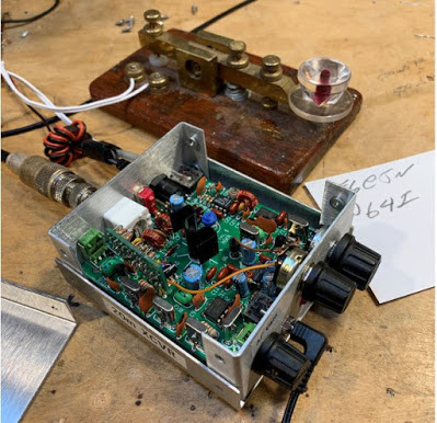
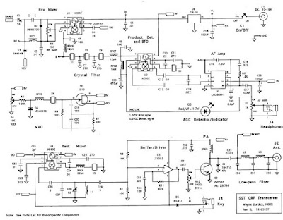
Bob KD4EBM recently sent me an amazing package of radio goodies. Included was a little metal box not much larger than a deck of cards. It is a 20 meter SST transceiver designed by Wayne Burdick N6KR during the late 1990s. This transceiver is built around three NE602 Gilbert Cell mixer chips. It arrived in my shack as I was struggling to understand the Gilbert Cell. TRGHS. It also put me back on the path of QRP CW righteousness. Thanks Bob. Thanks Wayne.
I e-mailed Wayne Burdick (now of Elecraft fame) to tell him I was now using the rig he had designed so long ago. Wayne e-mailed back, saying that the SST was the smallest “real” radio that he had ever designed. SST stands for Simple Superhet Transceiver.
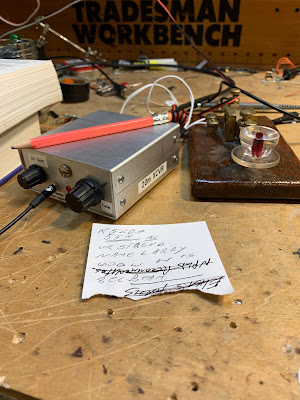
I’ve been using the SST every day for the last week or so. It is a pleasure to operate. I’m using it with the key from India that Farhan brought for me. It is truly QSK — the receiver stays on when I transmit. I’ve never used a QSK rig before and I can now see the big advantage that this provides: When I am responding to a CQ, I can immediately hear if the other guy put out another CQ or respond to someone else — I can stop calling at that point. My first contact with it was with F6EJN. Again, TRGHS.
I made two small mods to the SST: I added 1 uH to the RFC in the VXO; it now tunes 14.053 — 14.063. And I took out a noise blanker that had been installed. Removing the noise blanker left an ugly hole in the front panel which I promptly filled with a completely cosmetic machine screw.
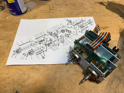
The HP8640B is a complicated machine. Above you see just one sub-assembly, and the page from the manual that describes it. This is what I’ve been working on. The little spring “tine” fell out of one of those discs behind the two control knobs. So I had to open this thing up, find the spot from which the tine had fallen, and glue it back in.
I used Gorilla Super Glue, followed 24 hours later by a dab of JB Weld “minute weld” dual epoxy. One of the other tines was about to fall out, so I went ahead and gave all the tines in this assembly the glue treatment. ( I bought some “Weld On” acrylic cement but the warnings on the label were quite sobering. So I left that can sealed up.)
This morning I put the thing back together. This is not easy. At one point a spring popped and a tiny metal part that is probably irreplaceable seemed to fly away into the black hole that is the shack’s carpet. I had just about given up hope when I found the thing sitting right in front of me on the bench. TRGHS.
The HP8640B fired up right away without trouble and the internal frequency counter is working fine.
As I noted in the last SolderSmoke podcast, a very nice community devoted to the HP8640B has developed around the world. Here are some of the notable participants:
Bill at Electronics Revisited is a very nice fellow with lots of experience on the HP8640B. He offered to sell me a replacement unit for the assembly pictured above. If you have an ailing HP8640B and are looking for someone to work on it for you, Bill is the guy you should talk to: http://www.electronicsrevisited.com/ He also very kindly offers to answer any questions you may have about the HP8640B.
Here is the e-bay page of the fellow in Bangalore who makes the brass gears. Mine are on the way!
And of course special thanks to Dave VE3EAC who alerted me to the falling tine problem and put me on the path to a successful repair.
The gears should be here in a few weeks, so that will be another opportunity to work on this HP8640B. Also there are some tines in the attenuator assemby that might reinforce with the glue treatment.
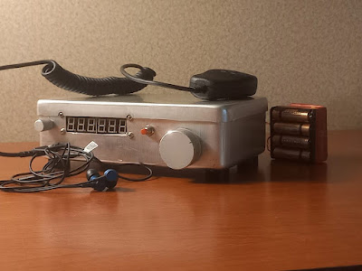
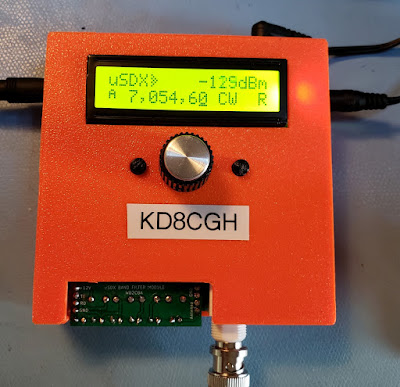
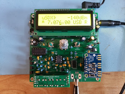
There is a new open source, home brew, multi band, multi mode QRP transceiver that grew out of the QRP Labs QCX. Through some serious magic it retains an efficient class E RF amplifier for sideband and digital modes. It crams impressive SDR capabilities into an Arduino. More info at https://groups.io/g/ucx/topics
The basic work appears to have been accomplished by Guido Ten Dolle PE1NNZ. It uses pulse width modulation of the PA supply voltage to transmit modes other than CW while retaining class E efficiency and uses a direct conversion SDR receiver.
This has an interesting development process with contributions by many, including the usual gang of suspects: Hans Summers, Ashhar Farhan, Manuel DL2MAN, Kees K2BCQ, Allison KB1GMX and Miguel Angelo Bartie PY2OHH. I apologize to the many others whose names I didn’t list.
The band switch multiband version by DL2MAN is even smaller, but with SMD components which I wasn’t ready to tackle yet.
BTW – your podcast encouraged me to go in this direction. I built a BITX 40, a uBITX (sent you a pix of it in an old Heathkit Twoer case), U3S, QCX and now my first step from kits to built from plans.