
This is cool in so many ways:
I like the RF amp along the back with the LP filter off to the side.
The stacked PC boards are very nice.
The Display — What can I say?
Having stations from the Philippines (DU) for the receiver demo. Nice touch.
Mesh-like side panels! And the plexiglass top! Wow!
PAINTING THE COPPER-CLAD FRONT PANEL BLACK! WOW! BLACK IS THE NEW COPPER!
Nice feet for the rig. Feet are key.
NO NOTICEABLE PHASE NOISE. No Si5351 output bleed-over.
Love the name: ZIA!! (That was my only contribution.)
Category: Hayward–Wes
SolderSmoke Podcast 177 Bicoastal Termination Insensitivity Unphased by Phase Noise

SolderSmoke Podcast #177 is available:
13 June 2015
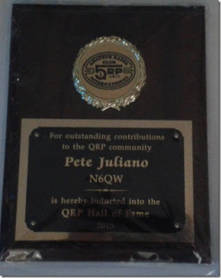
— PETE JULIANO INDUCTED INTO THE QRP HALL OF FAME
— Bench Reports: Bicoastal Bilateral Success: A Tale of Two Tias
Only 3 TIA rigs in the world? It depends…
Relay improvements in the BITX Builds
Straightening out amp problems
The many uses of copper foil
No phase noise or bleed-over troubles
Plug-in filters
Adjusting TIA amp gain on RX and TX (too much is not good!)
Getting the BITX to work with the CCI amp
Allison wisely prescribes 3 db pads
Curing hum by moving the power supply (duh!)
— Farhan’s New Minima — Crying out for an Si5351?
— Mike KL7R’s Web Site is Back (thanks to W8NSA)
— SolderLex: Rigs or Radios? We go with Rigs
— A ham rite of passage: Build a Dipole!
— What does your shack look like at the end of a project?
— MAILBAG
The CORRECT pronunciation of Belthorn
Multiplication and Division by 4
W8NSA, Vietnam, a Transoceanic and a 9V Battery
Our book: “SolderSmoke — Global Adventures in Wireless Electronics” http://soldersmoke.com/book.htm Our coffee mugs, T-Shirts, bumper stickers: http://www.cafepress.com/SolderSmoke Our Book Store: http://astore.amazon.com/contracross-20
Termination Insensitivity — Only Three TIAs in the World?

Termination Insensitivity. Is this like when your girlfriend dumps you and you just don’t care?
No. It’s more like this:
http://www.n6qw.com/TIA.html
Wes Hayward and Bob Kopski developed the Termination Insensitive Amplifier circuit back in 2009. With a bidirectional rig it is important that the crystal filter face the same impedance in both directions. Simpler bidirectional amps are impedance “transparent” in that their input impedance depends on what is on the output (and vice versa). The circuit that Wes and Bob developed solved this problem: these amps always look like 50 ohms. That’s very useful. When I was building my earlier BITX rigs, Farhan suggested that I try the termination insensitive amp circuits. On my latest project I followed his suggestion. At the same time, Pete was building a new BITX, also using the TIA amps.
Pete wrote to Wes and Bob and asked if anyone had followed through on their 2009 article by building a rig using this circuit. Wes said that he was unaware of any TIA rigs. It turned out that Tom Hall up in New York City had built one (video below). So I guess Pete’s rig is TIA 2 and mine is TIA 3! (But I was thinking, because of Pete’s Italian ancestry, shouldn’t we call his rig a Zia?)
Please let us know if you know of any other TIAS (or ZIAS!) out there.
Here is Tom Hall’s very FB TIA:
Our book: “SolderSmoke — Global Adventures in Wireless Electronics” http://soldersmoke.com/book.htm Our coffee mugs, T-Shirts, bumper stickers: http://www.cafepress.com/SolderSmoke Our Book Store: http://astore.amazon.com/contracross-20
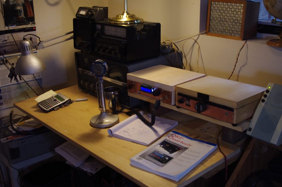
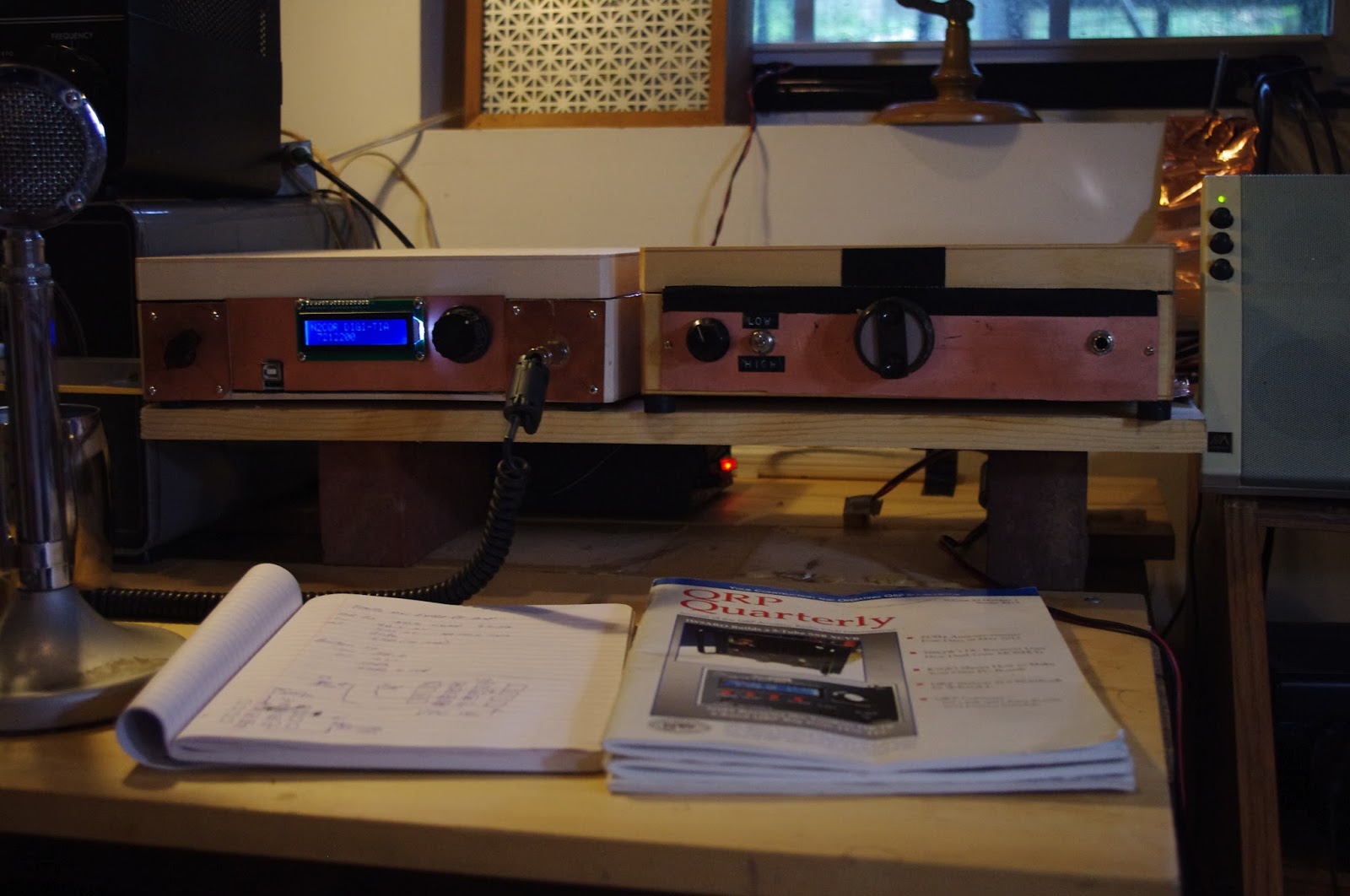
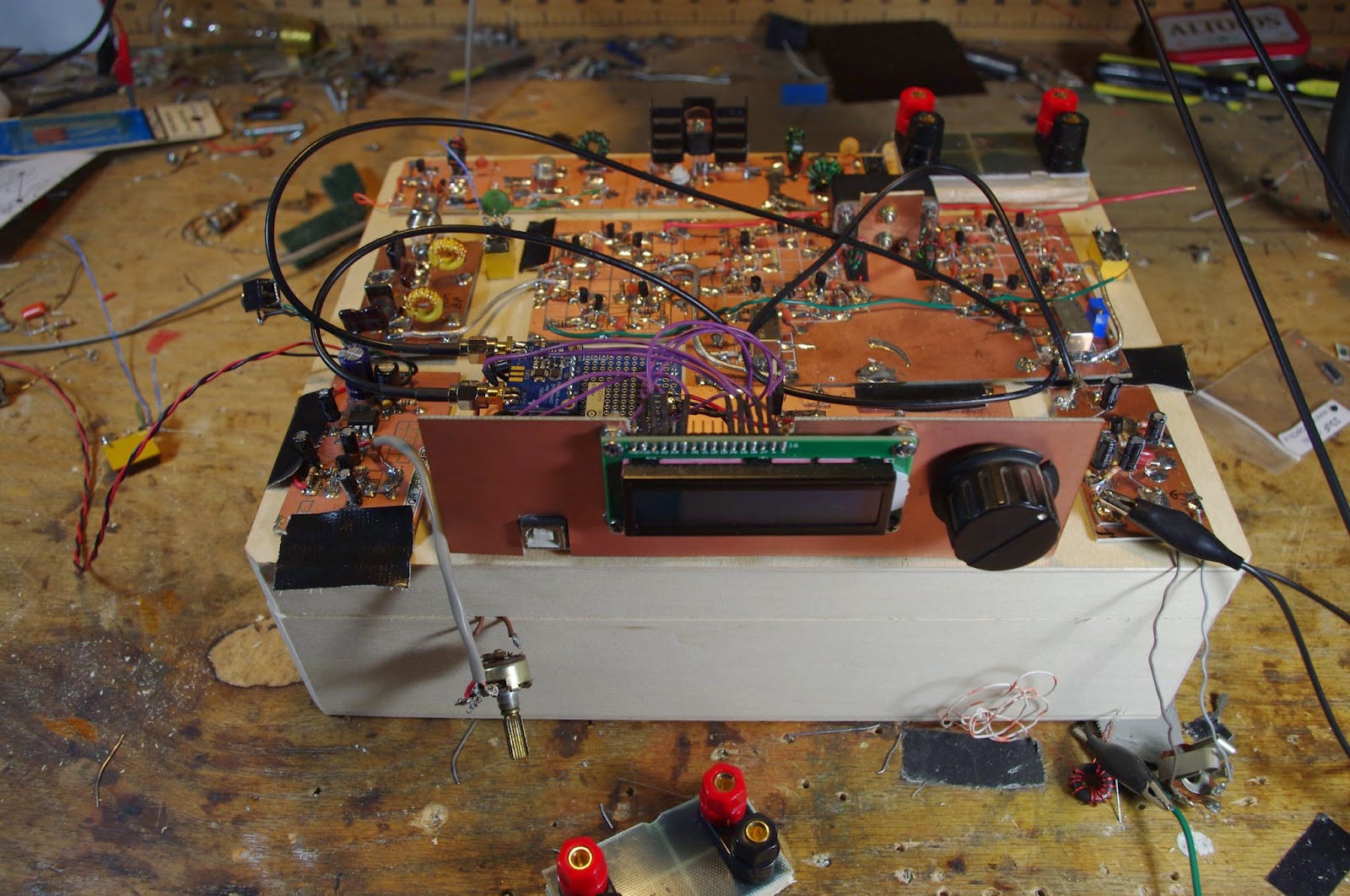
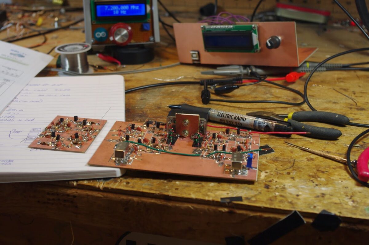
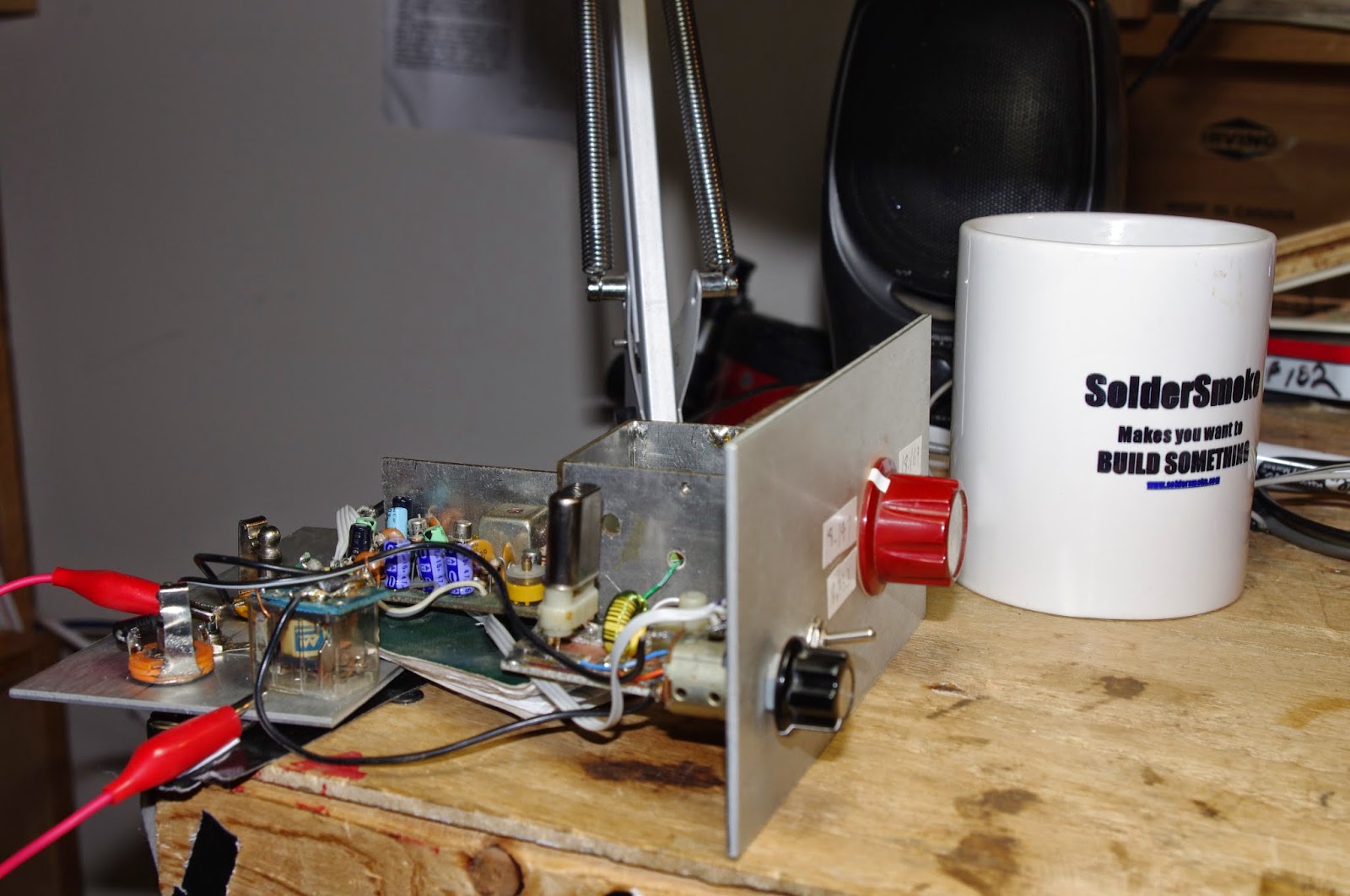
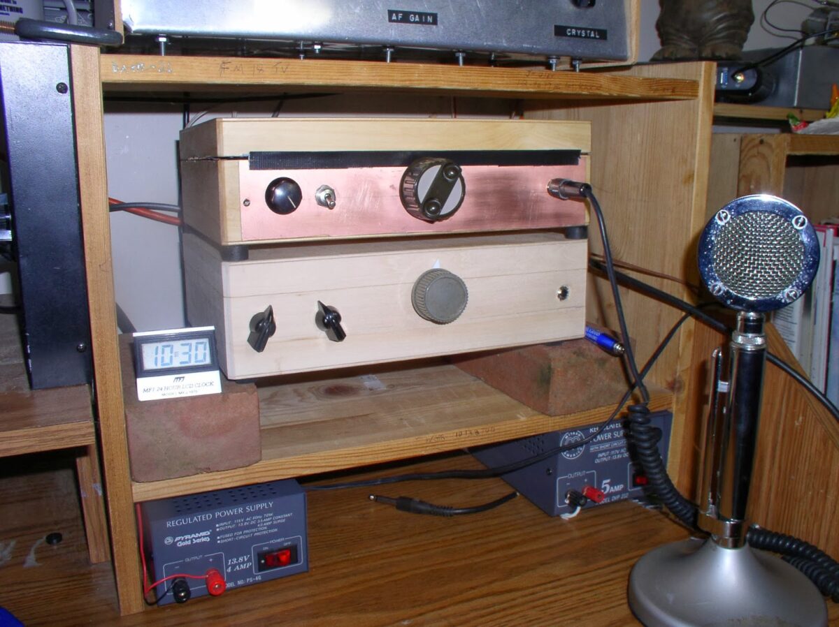
BITX DIGI-TIA Build Update #7: On The Air!
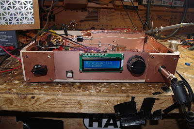
With lots of encouragement from Pete, I finally got the BITX DIGI-TIA on the air. The first contacts were made yesterday. I have it on 40 meter SSB. The finicky denizens of that audio-conscious band seemed to like the sound of the rig. I was almost reluctant to tell them it is homebrew (no need to stir up trouble!)
The plug in filter arrangement seems to work very well. This will allow me to put this rig on many other bands. All I have to do is build some additional filter boards and upload modified versions of the software. There is even space to make a plug-on socket for the crystal filter (the 9 MHz IF would not be cool for 17 meters).
I’m really pleased with the RF power chain (the original BITX chain). This time I built it all in a straight line along the back of the transceiver with lots of attention to shielding and grounding. There were no instability problems. The amplifiers did not try to be oscillators. I was shocked!
I did have to reduce the gain of the three termination insensitive transmit amplifiers. Using the chart in the 2009 Wes Hayward/Bob Kopski article, with just a few resistors you can set the gain. I had built them with 19.4 db gain each. This turned out to be too much — the slightest amount of audio into the SBL-1 was driving the amplifiers to peak output. So yesterday I changed all three amps to 15 db (I think that was what Farhan had in the original BITX). It only took me about 15 minutes and it seemed to take care of the problem. I am getting 7 or 8 watts out of the IRF-510.
T/R switching is very smooth and quiet using just two small 12V relays.
Thanks to Pete for the mil-pad boards and the encouragement (especially on the use of the Si5351). Thanks to Farhan for the BITX architecture. Thanks to Steve Smith for the Yaesu filter. Thanks to Wes and Bob for the TIA circuit. Thanks to Thomas in Norway for the Si5351 software. And Thanks to Allison for all the good advice.
Our book: “SolderSmoke — Global Adventures in Wireless Electronics” http://soldersmoke.com/book.htm Our coffee mugs, T-Shirts, bumper stickers: http://www.cafepress.com/SolderSmoke Our Book Store: http://astore.amazon.com/contracross-20
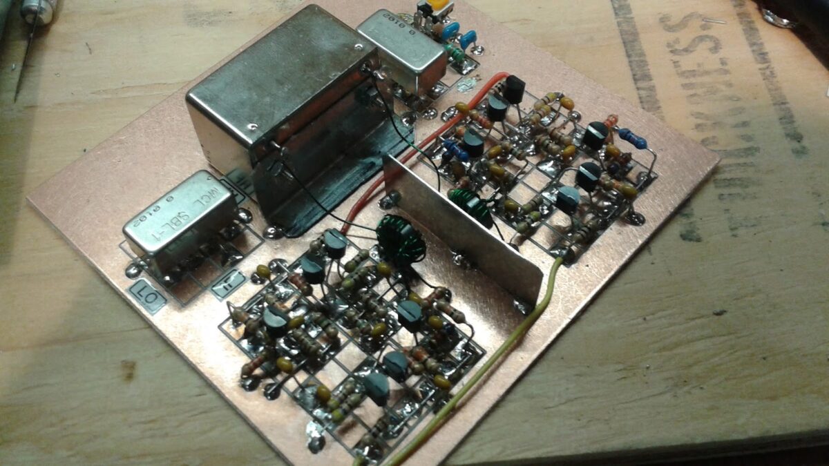
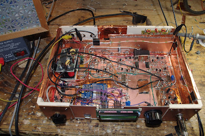
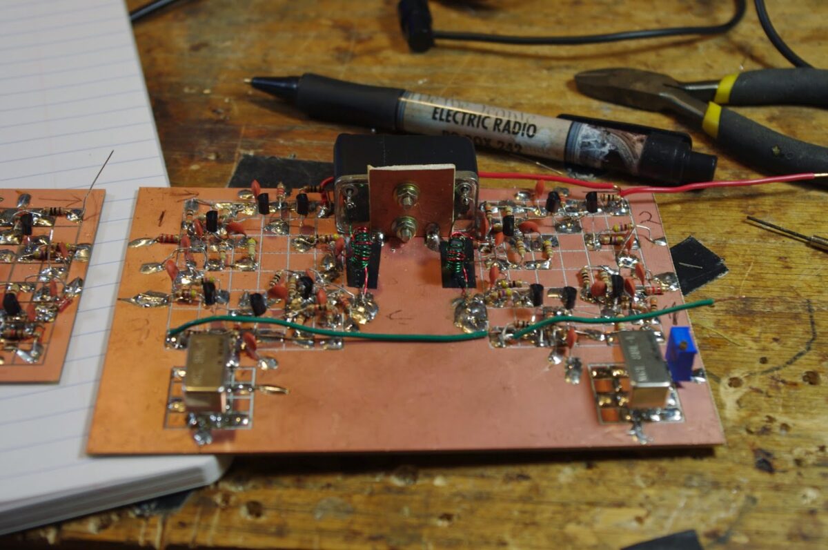
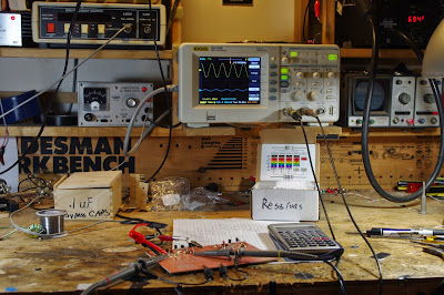
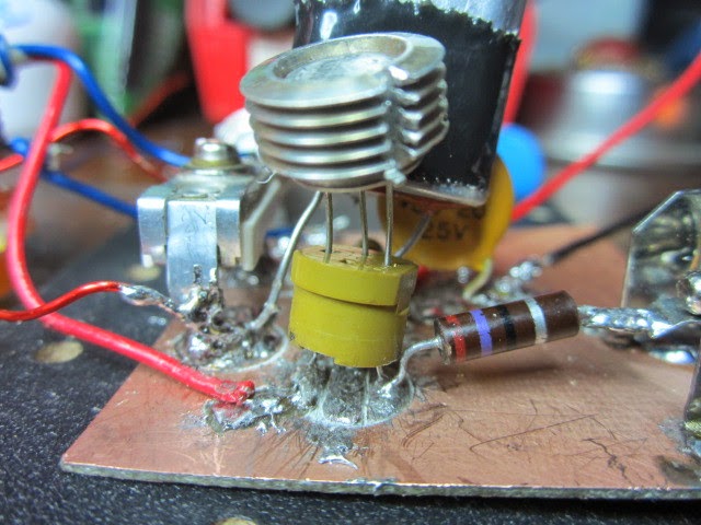
BITX DIGI-TIA Update #4
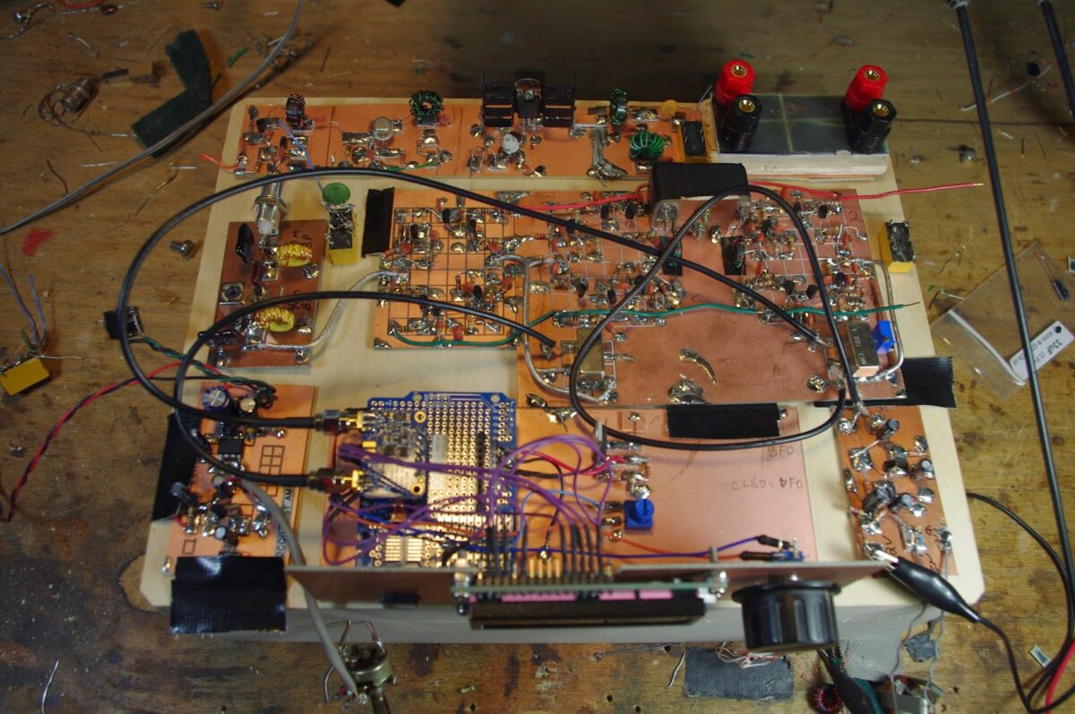
Lots of progress over the long weekend. Along the back you can see the three stages of the RF amplifier chain: 2N3904, 2N2218A, IRF510. I intend to add inter-stage shielding, and one long shield between the chain and the rest of the rig. Front and center is the Si5351 board (code by LA3PNA). Mic amp (which gave me a lot of trouble!) is to the right of the Si5351. AF (RX) amp is to the left (2N3904 and LM386). The big board in the center has the three Termination Insensitive Amplifiers (thanks Wes and Bob), the 9 MHz filter (thanks Steve Smith!) and the two SBL-1 mixers (thanks to Pete Juliano for the “mil-pad ” boards). And thanks to Farhan for the overall BITX concept and the TIA suggestion.
In the upper right you will see where the plug-in low-pass filter will plug in (a better picture appears below). I will use a similar plug-in for the band-pass filter. Combined with the BFO/VFO flexibility of the Si5351, this plug in feature should allow me to cover many bands with this rig.

Our book: “SolderSmoke — Global Adventures in Wireless Electronics” http://soldersmoke.com/book.htm Our coffee mugs, T-Shirts, bumper stickers: http://www.cafepress.com/SolderSmoke Our Book Store: http://astore.amazon.com/contracross-20
SolderSmoke Podcast 176: Knack-Related Conditions: Termination Insensitivity, Sideband Inversion, Dongle Modification, Area 5351 Conspiracy Disorder

SolderSmoke Podcast #176 is available! (And it is GOOD!)
http://soldersmoke.com/soldersmoke176.mp3
16 May 2015
Bench Update:
Pete releases some magic (amplifier) smoke
Pete’s new termination-insensitive transceiver makes first contact
Bill goes Yaesu (well, just a filter)
Juliano Mill-Pad boards
Termination Insensitivity is not a personality disorder!
Flip those Bilat Boards! Pete’s cool technique for bilat building
Bill’s project notebook and stage testing
Installing the W6JFR EMRFD SBL-1 Bal-Mod Mod
AREA 5351: Myths, Urban Legends, and Conspiracy Theories about the Si5351
A Rule of Thumb for Sideband Inversion
Dongle Madness and the Dangers of Dongle Modification
What is a dongle?
24 Mhz to 1.7 GHz right out of the box
Modification for 0-29 MHz
Tapping the IF of a Drake 2-B
Getting another one for VHF-UHF
Dongling Meteors, Satellites and Airplanes
SPRAT cover AD9850 in 1988! Three cheers for SPRAT (and QQ and QST).
Elecraft’s new Rig

Our book: “SolderSmoke — Global Adventures in Wireless Electronics” http://soldersmoke.com/book.htm Our coffee mugs, T-Shirts, bumper stickers: http://www.cafepress.com/SolderSmoke Our Book Store: http://astore.amazon.com/contracross-20
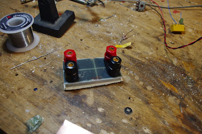
BITX DIGI-TIA Build Update #2 Installing and Testing Yaesu SSB Filter
Termination Insensitivity. It sounds like some sort of psychological problem, but it is not!
Our book: “SolderSmoke — Global Adventures in Wireless Electronics” http://soldersmoke.com/book.htm Our coffee mugs, T-Shirts, bumper stickers: http://www.cafepress.com/SolderSmoke Our Book Store: http://astore.amazon.com/contracross-20
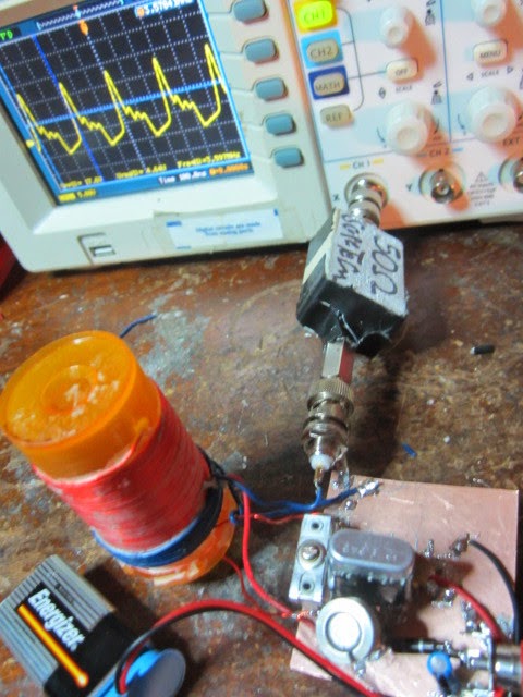
BITX DIGI-TIA Build Update #1 Building the First 2 TIA Amplifiers
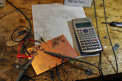
I started building the new transceiver today. I am tentatively calling it the BITX DIGI-TIA. Digi because it will have at its heart an Si5351 for BFO and VFO signal generation, and TIA because it will use Termination Insensitive Amplifiers (TIAs). These TIA amps are designed to present a 50 ohm impedance not matter what impedance you connect to the other end. This is a very useful feature when you are trying to get a certain impedance for a crystal filter in a bidirectional rig — you want the same termination impedances in both directions.
I built the “top” halves of two of the TIAs, using CNC-cut boards given to me by Pete Juliano. Thanks Pete! I like the boards, and I no longer have a thick coating of dried SuperGlue on my fingers.
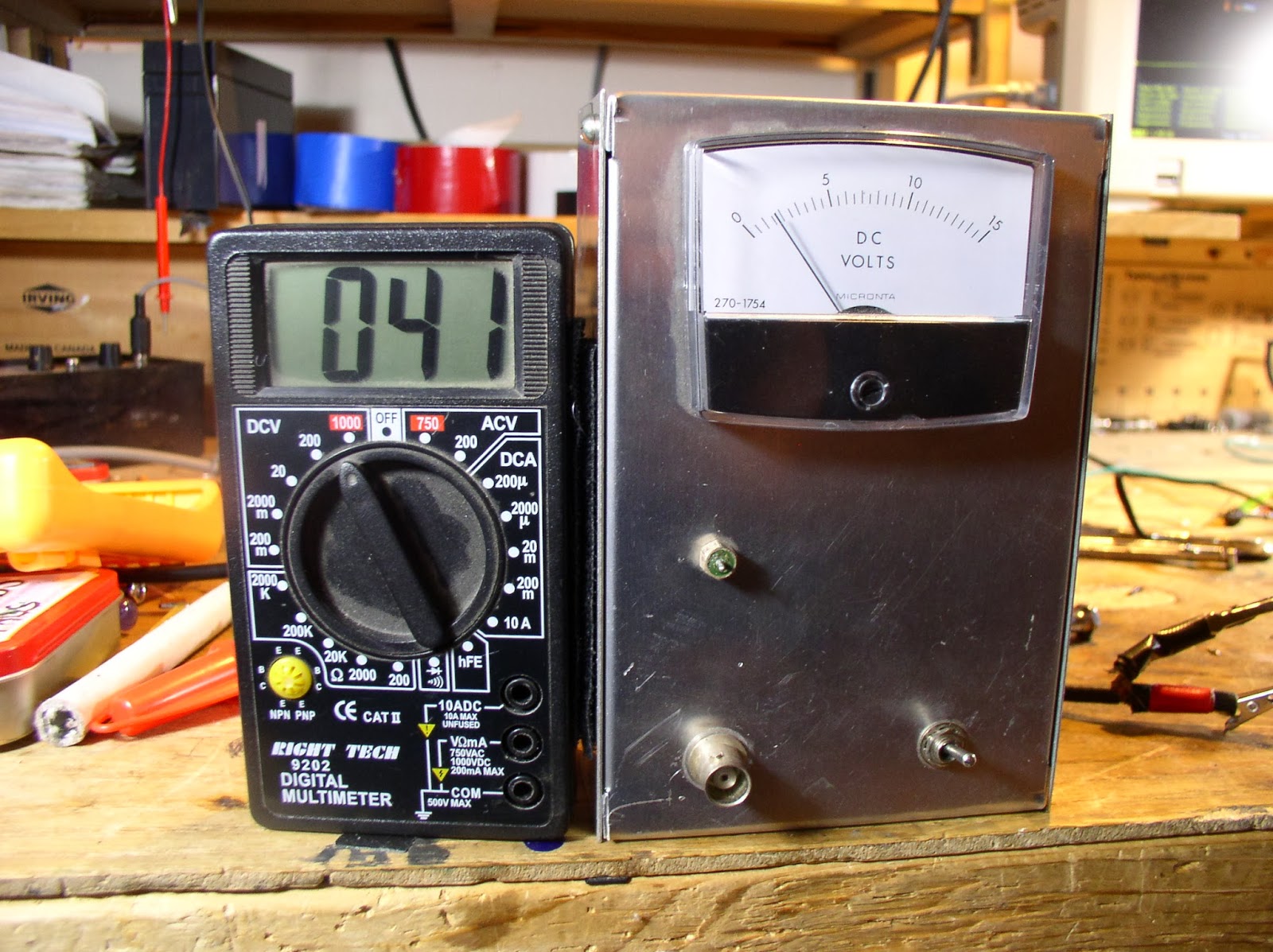
Both amps seem to be performing very well. Some numbers:
Current draw at 12 V (no signal) 30 ma.
Gain at 9 MHz (no load): Amp 1: 27.2 db Amp 2: 26.5 db.
I then took a 110 ohm load and put it across the output of Amp 1. Gain dropped to 23.9 db (as you’d expect). BUT HERE’S THE GOOD PART: The input voltage from my homebrew sig generator stayed exactly the same. Termination insensitivity.
More on these amps (with a link to Wes’s article) here:
Next I’ll put the 9 MHz filter between these amps and measure the shape of the filter passband.
Our book: “SolderSmoke — Global Adventures in Wireless Electronics” http://soldersmoke.com/book.htm Our coffee mugs, T-Shirts, bumper stickers: http://www.cafepress.com/SolderSmoke Our Book Store: http://astore.amazon.com/contracross-20
IF Selection — Which Filter for the New Rig?
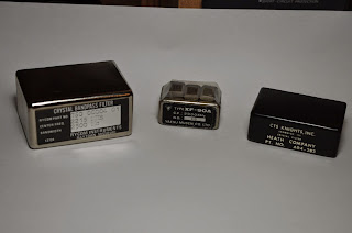
With some prodding from Pete Juliano, I am moving forward on my next transceiver. Same wood box enclosure (with copper flashing), but this time I am greatly relaxing some of the radical fundamentalist restrictions: Chips will be allowed. VFOs and VXOs will be replaced by an Si5351. Filters will not have to be homebrew. Pete has been putting his CNC machine to use and making me some nice boards with isolation pads already milled in. Oh, the luxury!
I am going to use the Termination Insensitive Amplifiers designed by Wes Hayward and Bob Kopski back in 2009. These are especially useful in bilateral type transceivers because they allow you to nail down the termination impedances on the crystal filter IN BOTH DIRECTIONS. That’s is important if you want the same filter shape on both transmit and receive.
But now, with the trauma of my unfortunate IF selection on the BITX 20/40 (now just 20, sniff…) in mind, what filter should I use on this rig? The three main candidates appear above. The 9 MHz Yaesu filter was given to me some time ago by Steve “Snort Rosin” Smith. The Heath filter (3.395 MHz) and the larger silver one (2.215 MHz) were given to me by Armand Hamel. (Thanks Guys!)
My main band of interest for this rig is 40. But if possible, I’d like to be able to use it on 15 and 12 meters, and maybe even 20 and 17, hopefully without having to change filters.
So what say the gurus? Which one should I use? Or should I put two of them in there, with provisions that would make it easy for me to move from one to the other?
Right now my inclination is to go with the 9 MHz filter, perhaps with the 3.395 MHz filter also available.
Our book: “SolderSmoke — Global Adventures in Wireless Electronics” http://soldersmoke.com/book.htm Our coffee mugs, T-Shirts, bumper stickers: http://www.cafepress.com/SolderSmoke Our Book Store: http://astore.amazon.com/contracross-20
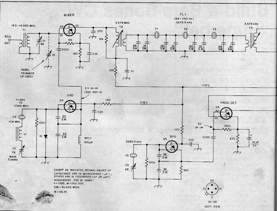
Termination Insensitive BITX Amps
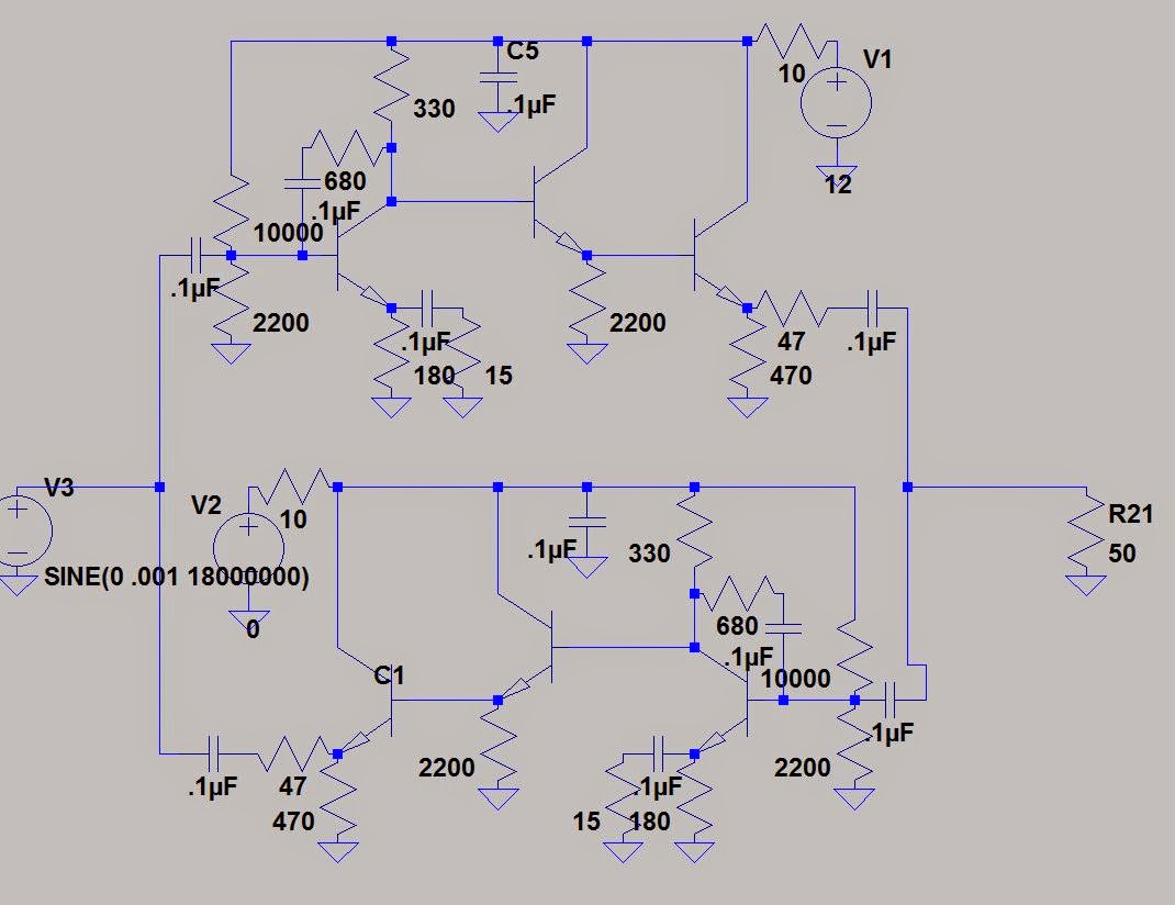
Back in 2009 Wes Hayward and Bob Kopski designed a termination insensitive amplifier block for use in BITX-like transceivers. Farhan urged me to use it. The advantage of this design is that the input impedance stays at 50 ohms no matter what you hang off the other end. That’s very helpful, especially when you start trying to get specific impedances at the ends of crystal filters. I’m planning on using this circuit in my next BITX. This morning I was playing around with it in LTSPICE. The “mirror” feature in that program is quite helpful when you are working on circuits like this!
Here is the article by Wes and Bob that describes this great circuit:
http://w7zoi.net/bidirectional_matched_amplifier.pdf
Our book: “SolderSmoke — Global Adventures in Wireless Electronics” http://soldersmoke.com/book.htm Our coffee mugs, T-Shirts, bumper stickers: http://www.cafepress.com/SolderSmoke Our Book Store: http://astore.amazon.com/contracross-20
Homebrew Heroes at Rickreal Hamfest: W7ZOI and WA7MLH

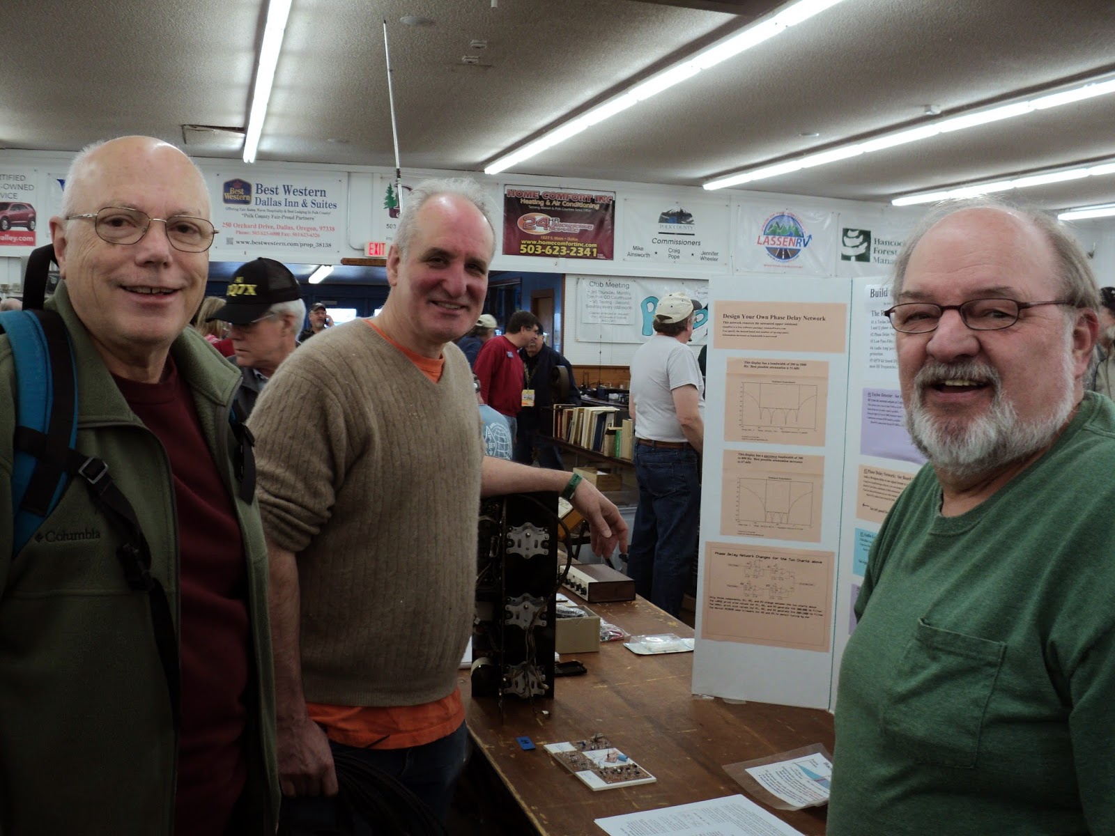
Bob N7SUR was getting discouraged. The hams at the Rickreal Hamfest didn’t seem really interested in his display about homebrewing. Then THE RADIO GODS INTERVENED! (thunder). Two TITANS of homebrew appeared at Bob’s table. Keep up the good work Bob, Thanks for the e-mail and the great picture of you with Wes and Jeff.
To N2CQR, N6QW
Feb 15 2015
The Salem, Oregon, Repeater Association puts on two hamfests each year
at Rickreal. This event was mentioned in SolderSmoke #78. During the
last two events I’ve taken a “science project” display and circuit
boards to encourage more hams to experiment. The boards encourage
experimenters to use software packages to design and build their own
receiver modules. It is uncommon to see this type of material at the
event.
Audience interest has been underwhelming. Perhaps a dozen participants
have shown interest in my displays. In fact, I almost left the displays
home last Saturday.
In the course of the morning, two guys approached. The older guy had a look of
familiarity. He looked like a guy in the SolderSmoke blog. Bill,
N2CQR, was pictured sitting with him in California over coffee.
I blurted out, “are you ZOI?” He replied “yes” and I told Wes Hayward,
W7ZOI, it was nice to meet him. (That was a bit of understatement).
With Wes was Jeff Damm, WA7MLH, who built many of the circuits included
in the book “Solid State Design.” I suggested to Jeff he no longer
looked like a hippie, which is the style conveyed by his webpage. Jeff
said he had recently cut his hair.
We spent more than an hour sharing ideas and discussing various topics.
My focus was on encouraging experimentation. Kit building may be a nice
first step. I want to see builders pursuing more advanced
investigations. Wes noted the software and simulation tools available
for free it’s never been a better time to try out ideas. Wes commented
on the contribution of amateurs and how we often have fewer restrictions
to pursuing our interests. He emphasized measurement tools. I should
look more at noise figure in my receiver experiments. He was very
supportive, which contrasts with my recent experiences on various
internet groups.
Wes and Jeff were looking for Rick Campbell, KK7B, and Bob Larkin,
W7PUA. Imagine, the three authors of Experimental Methods in RF Design
(EMRFD) frequenting a little hamfest in rural Oregon. Yet, few people
knew they were there.
The experience reinforced my interest in continued experimentation.
I’ll take my updated displays back next time. Perhaps our efforts reach
a larger audience than we first realize.
Bob-N7SUR
Our book: “SolderSmoke — Global Adventures in Wireless Electronics” http://soldersmoke.com/book.htm Our coffee mugs, T-Shirts, bumper stickers: http://www.cafepress.com/SolderSmoke Our Book Store: http://astore.amazon.com/contracross-20
Kansas Mighty Mite
Our book: “SolderSmoke — Global Adventures in Wireless Electronics” http://soldersmoke.com/book.htm Our coffee mugs, T-Shirts, bumper stickers: http://www.cafepress.com/SolderSmoke Our Book Store: http://astore.amazon.com/contracross-20
Broadening the Barebones Barbados Receiver
I‘ve been working on the crystal filter of the Barbados Barebones Superhet receiver. This was designed by Doug DeMaw in 1982. This one was built by Dale Parfitt W4OP and then repeatedly modified by me. It is now on 17 meters with a crystal-switchable VXO. Earlier I had made a very crude attempt to broaden the filter from its original very narrow CW configuration. This week I did this again, but this time I actually characterized the crystals and used Wes’s LDA and GPLA software (from EMRFD) to design the filter.
I played with the capacitor values and finally got the 3 kc bandwidth I wanted, but I’m having trouble getting rid of the ripple. I know this is dependent on the impedances at the two ends. The programs say I need 2000 ohms.
I’m kind of puzzled about how Doug DeMaw did this with his original design. For his crystals and his 250 Hz (!) bandwidth he said he needed 450 ohms. He used 4.7:1 turns ratio transformers at either end and said that by putting 10k resistors across these transformers he got the needed impedance. I can see how this would work looking into the gate of the 40673 IF amp, but looking back at the drain of the 40673 mixer, I’m not so sure that that would yield 10k. (See schematic below.)
But who am I to doubt Doug? So I assumed he was correct about the 10K and I re-wound the transformers with a 2:1 turns ratio, thinking that would get me closer to the needed 2k. But the ripple is still there. I guess I could use a return loss bridge at this point…
I don’t know whether this is worth messing with anymore. The receiver sounds nice. The 3kHz bandwidth gives it a nice sound, and the ripple doesn’t seem to be noticeable That FAR circuits board is tightly packed and difficult to work with. So, should I leave good enough alone, or should I proceed with fanatical ripple eradication. Any advice?
BTW: Why is it that receivers always seem to sound better when opened up (as above) on the workbench?
Our book: “SolderSmoke — Global Adventures in Wireless Electronics” http://soldersmoke.com/book.htm Our coffee mugs, T-Shirts, bumper stickers: http://www.cafepress.com/SolderSmoke Our Book Store: http://astore.amazon.com/contracross-20
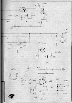
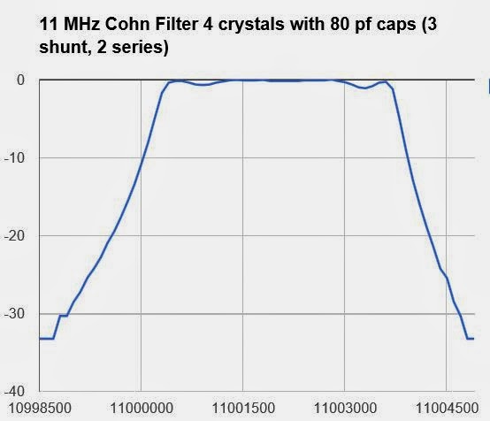
BITX 17 Build Update: More Filter Maintenance
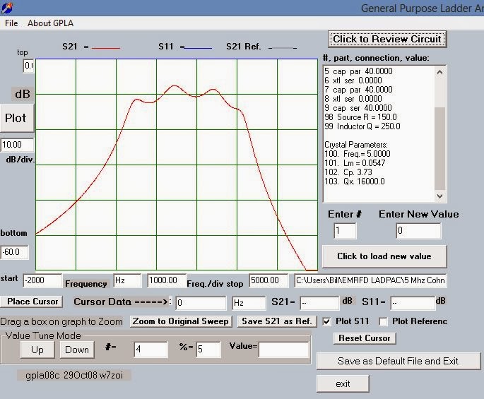
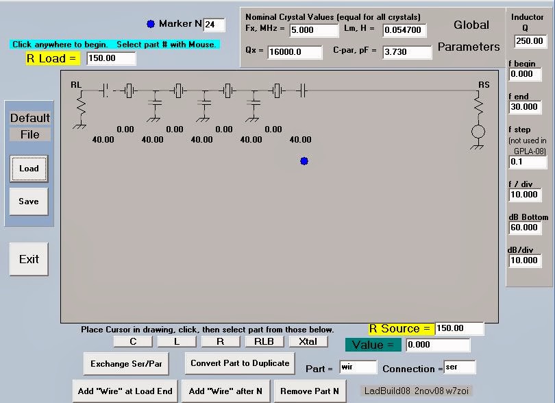
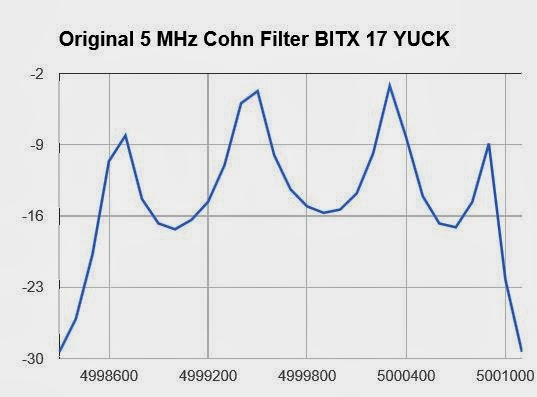
Having had great success in straightening out the 11 MHz filter in my BITX 2040 (scroll down for details), today I decided to see what I could do with the filter in my 17 meter BITX (four 5 MHz crystals in Cohn MIN LOSS configuration, with 40 pf caps all around). The key to my success in all this has been the filter programs that came with EMRFD. After characterizing my crystals with the G3UUR method, I plugged the values into LADBUILD 8, then took a look at the expected results. As you can see from the image above the predictions were not pretty. Yuck. Lots of ripple and lots of insertion loss.
I went into the rig and using my DDS sig generator and my RIGOL ‘scope, measured actual performance. It looked worse than the prediction (part of the worsening is a difference in vertical scale):
LADBUILD lets you play around with the values of the components in the filters. I know that ripple is usually related to an impedance mismatch. So in LADBUILD I experimented (virtually) with different impedance values at the end. I noticed that at about 1000 ohms, the ripple and insertion loss got better:
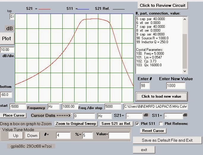
So I went and built two broadband toroidal transformers. 4 turns primary with 12 turns secondary (1:9 Z). I’m assuming that the BITX has around 150 ohms at either end of the filter. That would put about 1350 ohms at the ends of the filter.
Here are the results:
Much better.
Our book: “SolderSmoke — Global Adventures in Wireless Electronics” http://soldersmoke.com/book.htm Our coffee mugs, T-Shirts, bumper stickers: http://www.cafepress.com/SolderSmoke Our Book Store: http://astore.amazon.com/contracross-20
On the Origins of “Ugly”
Yesterday I posted a link to a Maker Blog article about a fellow who designed a DIY, junkbox, homebrew machine tool. I noted that in the book “The Ugly American” the hero also makes use of old engine blocks. Farhan commented on this, reminding me of the connection between “The Ugly American” and our beloved ugly construction method: This is from Todd’s (wonderful) QRP Pops site:
http://www.qrp.pops.net/ugly.asp
The Origin of the Term “Ugly Construction”
Roger Hayward, KA7EXM and Wes Hayward, W7ZOI coined the term “Ugly Construction” while writing the “Ugly Weekender” published in the August 1981 issue of QST. I asked Wes about this in 2009. The term was a takeoff from the 1958 book entitled The Ugly American by William Lederer and Eugene Burdick.
Our book: “SolderSmoke — Global Adventures in Wireless Electronics” http://soldersmoke.com/book.htm Our coffee mugs, T-Shirts, bumper stickers: http://www.cafepress.com/SolderSmoke Our Book Store: http://astore.amazon.com/contracross-20
BITX 2040 Build Update #10 : Fixing my Filter
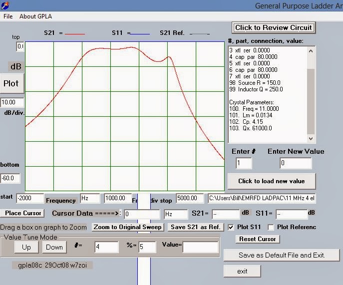
That dip on the high side of the passband was bothering me. The GPLA crystal design program predicted it, and indeed, when I measured the performance of the actual filter, there it was. The rig was working fine — the receiver sounded fine and everyone tells me that it sounds great on transmit. But still, it bothered me.
So I started working out with the various crystal filter software packages.
This filter was — sort of — a Cohn Min-loss filter, but I had built it with four crystals and three shunt caps (80 pf each) and no series caps at the input/output. This morning I decided to see what would happen if I put the series caps in there. Here is what Wes’s GPLA predicted:
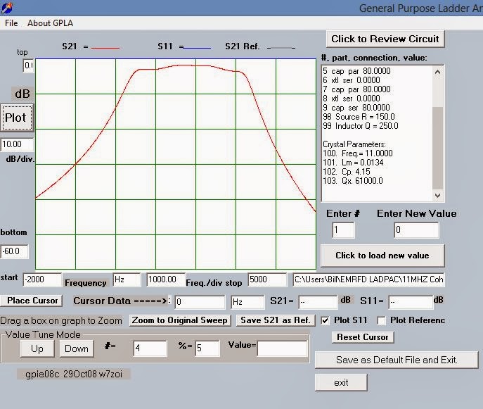
Wow, that looked a lot nicer. And the 150 ohm terminations seemed to be just about perfect for the BITX design — no need for impedance transformation. I heated up the soldering iron and searched the junkbox for suitable caps (I found 2 82 pf caps — close enough).
Here is what the results looked like (I didn’t measure insertion loss so the top of the curve is just the peak of the response curve).
Exactly as predicted! Thanks Wes! And thanks to Farhan for encouraging me to characterize my crystals and to use the available software
Now I have to go back and de-ripple the 5 MHz filter in my BITX 17.
Our book: “SolderSmoke — Global Adventures in Wireless Electronics” http://soldersmoke.com/book.htm Our coffee mugs, T-Shirts, bumper stickers: http://www.cafepress.com/SolderSmoke Our Book Store: http://astore.amazon.com/contracross-20
Back to the W7ZOI/W7PUA Power Meter

Recent e-mails and Facebook postings from Jim (W8NSA) and Michael (AA1TJ) got me thinking about my old W7ZOI/W7PUA power meter. The 15 inches (38 centimeters) of snow that fell last night gave me the day off — and time to play with this very useful and interesting piece of gear.
The last time I used it I remember thinking that a digital readout would be nice. But I didn’t feel like going back into the world of Arduinos and LCD screens. So I came up with a real Kludge solution: I had cheap little DVM that I wasn’t using, so I just velcroed it to the side of the power meter. That little connector above the BNC is the output for a DVM. I might work on calibration later today.
Wes has some very interesting info follow-up info on the meter on his site: http://w7zoi.net/qststuff.html
I really like the part about how the meter is so sensitive that you can see the thermal noise in the input circuit and can actually measure the strength of signals from your antenna.
I think I might need a low pass filter at the input of the meter. There are strong FM broadcast transmitters in this area (some of you may have listened to them in the background of early episode of the SolderSmoke podcast!). I notice that just bringing my fingers close to the input causes the meter and the DVM readout to swing up. That’s not good.
Our book: “SolderSmoke — Global Adventures in Wireless Electronics” http://soldersmoke.com/book.htm Our coffee mugs, T-Shirts, bumper stickers: http://www.cafepress.com/SolderSmoke Our Book Store: http://astore.amazon.com/contracross-20
BITX 2040 Build Update #9: On-the-air Observations

The BITX 2040 has moved from the bench to the operating position and is producing a steady stream of contacts on 20 and 40 meters. In the picture above it is the rig with the copper-clad front panel (the BITX 17 is below it). It has already crossed the pond on both bands.
Some observations:
I get significantly more power out on 40 than on 20: about 7.2 watts PEP on 40 and about 4.4 watts PEP on 20. I saw a QST article that showed similar frequency/power out variations from IRF510 amps. But I notice I get more power out from my 17 meter rig. On that rig I am using trifilar (9:1 Z) transformer instead of the standard BITX bifilars.
My 40 meter receiver is LOUD. Too much AF out. I am not used to having this problem! On this rig I am using the same discrete component 2n3904 2n3906 transformer-less circuit that I used in the BITX 17. But AF out on 40 was so loud that I had to go back and add 20 k ohms to the top of the volume control pot. I didn’t have this problem with the 17 meter rig, and I didn’t have it on 20 with this rig. Any ideas why this rig would be so loud on 40?
I still want to go in and fine tune the crystal filters in both rigs. I am studying the various software packages out there (especially Wes’s LADPAC). I hope to get rid of the ripple.
In most of my contacts with these rigs, I end up describing the circuit and its Indian origins. Most people are really fascinated. Yesterday W1IDL in Michigan suggested that I contact my Indian friends and get some assistance in making some Hindi or Urdu labels for the rig and the controls. I think that is a very cool idea.
Our book: “SolderSmoke — Global Adventures in Wireless Electronics” http://soldersmoke.com/book.htm Our coffee mugs, T-Shirts, bumper stickers: http://www.cafepress.com/SolderSmoke Our Book Store: http://astore.amazon.com/contracross-20
BITX Build Update #11 — Peakin’ and Tweakin’
Oh how I love the sound of a newly built receiver! I’m sitting here listening to G0MJS on 17 meters. Lots of other stations from across the pond coming in very nicely.
Earlier in the week I had some sensitivity problems. I could hear the noise floor, but just barely. And the receiver just seemed to have trouble inhaling. So I started poking around. It seemed that each poke improved things a bit. I had used Farhan’s original schematic (mostly). Later versions put an additional transistor in the IF amp. So I went ahead and added that mod. That helped a bit. Then I noticed that BFO energy was getting into the AF amp. So I put a .1uF cap to ground at the input to the AF preamp. That took care of the RF and did no damage to the AF.
But the rig still seemed a bit hard of hearing. This morning Farhan advised me to take a look at the mixers. I used some junk-box diodes that I didn’t know too much about… I measured the forward resistance and found it to be quite a bit higher than the usual 1N914s. So I switched all 6 mixer diodes. That helped noticeably.
I also checked the input bandpass filter. It seems OK. In the process I learned to use the EMRFD filter programs (thanks Wes) and the ELSIE filter program (also very nice).
Anyway, the rig sounds great now. On to the transmitter.
Farhan advises building the power amplifier on a separate copper clad board. But I have room for it on my main board. Should I live dangerously?
Our book: “SolderSmoke — Global Adventures in Wireless Electronics” http://soldersmoke.com/book.htm Our coffee mugs, T-Shirts, bumper stickers: http://www.cafepress.com/SolderSmoke Our Book Store: http://astore.amazon.com/contracross-20