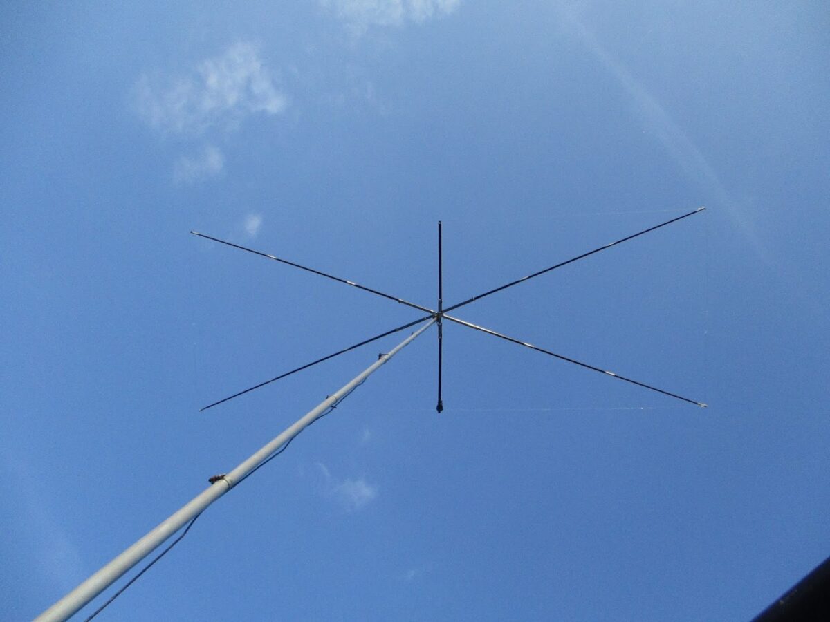
I had a very nice contact on 17 meters yesterday with Jan DL1YC. It was a rare Moxon-to-Moxon contact, with homebrew 17 meter Moxons on either end. Jan’s is a bit cooler than mine: His is flat, without the “blownout umbrella” support that we see in mine (below) and in the Hex Beams. Jans told me that he achieved this flatness by starting out with very long telescoping fishing poles — he discarded the the thin portions of the pole and used only the more rigid pieces. (I used 16 foot, 5 piece Shakespeare Wonderpoles from Amazon.) I think he also used thin wire for the elements. The crossbar that you see in the picture above is there to support a balun at the feed point — without the cross bar the balun and the feedline would cause the balun to droop. I couldn’t resist a little front to back testing. Jan’s antenna does not have a rotator — he used the “Armstrong” method of antenna pointing. I didn’t want to make him go outside to spin the thing around by hand, so I just turned mine and asked him to take note of the difference front to back. He saw 3 S units. 18 db. Not bad. Jan said his antenna weighs about 8 pounds — mine is very similar at 9 pounds. Jan expressed some concern about UV deterioration of the fishing pole fiberglass. Mine has been up there three years without any problems. Like me, Jan had considered “nesting” an element for another ban (perhaps 20 or 12) but — like me– had concluded that this would be too difficult.
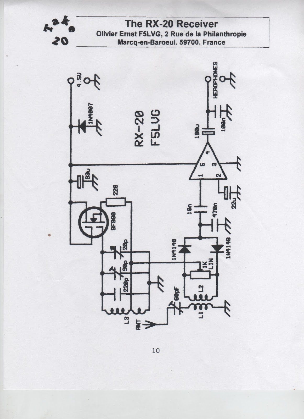
At the instigation of Bob N7SUR I’ve been working on a simple, easy-to-reproduce Direct Conversion receiver for 40 meters. I’m building this for my nephew John Henry, and I’m hoping this will be a circuit that others can use to break into the ELITE corp of successful ham receiver builders. Coincidentally Joh in Freiburg Germany is working on a very similar project — we have been comparing notes. At first I used an FET detector described by Miguel PY2OHH. It worked, but at night the AM detection of powerful shortwave broadcast stations drowned out the amateur signals. So Joh and I started to explore detectors that would eliminate this problem. I went with a version of one described in SPRAT by F5LVG ( “The RX-20 Receiver”- see below). Very simple: A transformer to two back-to-back diodes with a 1K pot to balance the signal from the VFO. OM Olivier used a very, very cool transformer: he took two small, molded chokes and simply glued them together! 22uH choke as the primary, 100uH choke as the secondary. I went with one of the toroidal transformers that Farhan left me when he visited in May. I’m using a varactor-controlled ceramic resonator VXO (no Si5351 in this one!) and a non-IC AF amp designed for use with ear buds (the world is awash in ear buds). It is a “singly balanced” design with the incoming RF signal being the one “balanced out” in the detector. Last night the receiver passed the AM breakthrough test. The SW broadcast monsters were balanced out and kept at bay. This morning the receiver passed The Boa Vista Rooster Detection Test. I fired up the receiver and heard an operator speaking Spanish with a Brazilian accent. When I heard the rooster crowing in the background I knew it was Helio PV8AL from Boa Vista Brazil. TRGHS — this little receiver is a winner. I’ll try to post a schematic soon. And hey — look at what wonderful IBEW (International Brotherhood of Electronic Wizards) project this is: Instigation and inspiration from Oregon. Some design ideas from Brazil. A French detector circuit described in a British QRP magazine. A transformer from India. A collaborator in Germany. And finally, the rooster of Boa Vista.
Let’s not forget Wes Hayward W7ZOI for bringing back (in 1968!) the neglected Direct Conversion idea.
Pete WB9FLW alerted us to the work of Peter DK7IH, a very talented homebrewer who recently followed the lead of Pete N6QW in building some really small SSB transceivers. Here is his Micro QRP SSB rig:
You can see more of his fine work here: https://radiotransmitter.wordpress.com/ https://www.qrz.com/db/DK7IH Have you guys noticed how many Peters there are among homebrewers, especially among SSB homebrewers? Just from recent mentions on this blog: Pete Juliano N6QW Pete WB9FLW Peter Parker VK3YE Peter DL3PB Peter W1UO Peter GW4ZUA Peter G6GNR Peter VK2EMU Peter VK2TPM Peter HA5RXZ Peter DL3JIN
There is a lot of radio history in this shortwave transmitting station. I came across it tonight with my BITX DIGI-TIA rig. It was on 7.215 MHz transmitting in Indian (South Asian) languages. But alas, the signals were not from distant India (home of the BITX!). Instead — as often happens these days — the signals were from a relay station. In this case they came from relatively nearby Germany, from the Nauen transmitter site. Check out the Wikipedia page: https://en.wikipedia.org/wiki/Nauen_Transmitter_Station
In spite of being a bit off frequency, sTef, DL1FDF (aka VY1QRP) has been inducted into the Color Burst Liberation Army. Congratulations sTef! Normally we would requite operation on 3.579 MHz, but sTef has been granted special dispensation because 1) he doesn’t have a 3.579 MHz rock, 2) our stock of this crystal has been depleted, and 3) he actually made a contact with this rig, working II3ICZ in Venice. FB sTef. If anyone has a color burst crystal for sTef, please let us know.
sTef writes:
I would like to say „Thanks” to both of you for your ongoing inspirations in soldering and homebrewing. After 15 years out of ham radio it were you two guys who got me back into the world of -> SOLDERSMOKE. Thanks for that.And belive me been away for 15 years and now getting back into it feels a sometimes a little bit too “digital“ …. ARDUINO or NOT TO ARDUINO ? This is the question….
Anyway…
So what could be more sophisticating than having a MMM ready on the work bench and answering a CQ call on 40m with that thing and be heard.
Yes, the first QSO today with my MMM was for you both.
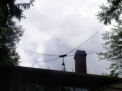
I worked the Italian Radio Station II3ICZ. I was 559 into Venice with 0.5 watts from the MMM into my full-size triple leg for 40m.
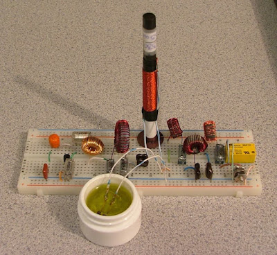
The saturable magnetic frequency septupler. The tiny computer memory core is submerged in olive oil (Italian…naturalmente).
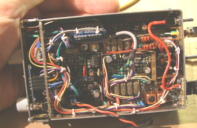
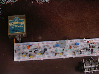
Not a very good picture, but here’s the 1600Hz tuning-fork, fork oscillator, SRD pulse generator, PLL S/H phase-detector (diode gate), differential amplifier D.C. amplifier, and part of the 500kHz VCO.
I was pleased to have made the first contact with my tuning-fork transmitter this evening. My contact, N1QLL, runs a pretty B&B on the Maine seacoast, midway between Bar Harbor and Cutler. Jerry was operating a solar-powered QRP station. I found a follow-up email from him when I came up to the house for dinner. He’s asking for a better explanation of my set-up. I can’t wait to tell him about the passive frequency septupler made from an East German computer memory core, heat-sinked in a thimble of olive oil.
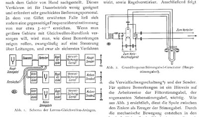
My signal was also logged by a number of automated “Reverse Beacon Network” receivers (image attached) located in Ohio, North and South Carolina, Virginia and Pennsylvania…not bad for 90mW on 80m. Please note that my operating frequencies, 3,528.0 and 3,539.2kHz, are the 2,205 and 2,212th harmonics, respectively, of my 1,600Hz tuning-fork frequency reference. FYI: the third attached image illustrates the block-diagram and tuning-fork reference oscillator circuitry for three common-wavelength AM broadcast transmitters operating in Berlin, Stettin and Magdeburg, Germany from 1928 through the mid 30’s. A central 2,000Hz tuning-fork generated reference carrier was transmitted by landline to transmitters in the aforementioned cities whereupon the 529th harmonic was generated, amplified and broadcast at 1,058kHz. The equipment was designed by the Berlin-based firm, C. Lorenz A.G.. The fourth image details Lorenz’ technique of frequency multiplication via saturable magnetic iron-core inductors. My septupler operates in an identical fashion. A very pleasant day…
Mike points out that this is a work in progress. He hopes to cross the pond (the Atlantic!) soon. Here is a update from Mike: A nasty cold has delayed work on the 20 meter implementation, although some of the time I’ve spent crashed on the sofa was put to use redesigning the loop filter network. I think yesterday might have been my “hump” day so I’m looking forward to getting in some quality bench-time over the weekend.
By the way, my PLL-based transmitter frequency stabilizing circuit has much in common with a garden-variety frequency-synthesizer. Obviously, the tuning-fork frequency reference is the main point of departure. My sampling phase detector, for example, was old hat by the mid-1960’s. Nevertheless, this has been a fun project.
This is almost enough to make me abandon my analog, discrete component, HDR fundamentalism. Check out that display. And that StereoAM mode in which the upper and lower sidebands go to the left and right headphones “useful for CW”… Wow, that’s seems like a step beyond binaural.
Don’t miss Parts 2-4 –They are all on YouTube and will appear in the right hand column when you are watching Frank’s videos. But I couldn’t resist embedding the video that shows the hardware. Note: the oscillator is an Si5351! Yea! And the LP filter board comes from Hans Summers.
Beautiful work Franz! Thanks for making the videos. 73 Bill
Michael updates Peter (and us!) us on his efforts of this week:
Grüss Peter!
Thanks for the nice message. Yes, I knew that you were going to be QRV with your ZnO transceiver but I never heard if you had made any contacts. I guessed that you had not, otherwise I’m sure you would have let me know.
Again, I think your circuit looks really great! It’s amazing to think you managed to squeeze 500uW from a scrap of oxidized zinc-plated steel. Even if you didn’t make a contact, what you are doing is really fantastic. Congratulations on the creation of this amazing radio!
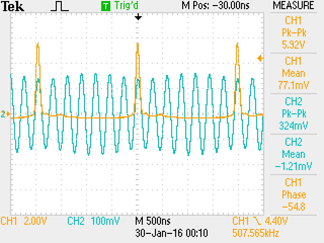
Okay, so I spent most of the afternoon at the workbench. Thus far I’m only using a single SRD (step-recovery-diode…1N5401 rectifier). Of course the result is a unipolar pulse. The idea did work as planned, however the power only increased by 2.24dB. The maximum RF output power is now 230uW. At least the SRD makes a pretty pulse 🙂
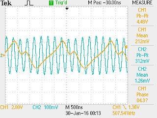
Please find two scope captures attached to this message. The first (0002) shows the SRD generated unipolar pulse. As you can see, the pulse width is nearly perfect for the job. The second trace shows the output RF waveform. The worst spurious energy is ~20dBc. The second image shows the 507kHz waveform at the unijunction emitter along with the output RF waveform.
The beacon is presently off the air, but I look forward to trying my luck tomorrow with a back-to-back pair of SRDs. A bipolar pulse pair will provide a shock impulse once every 3.5 cycles, instead of once every 7 cycles with the present unipolar drive pulse. The bipolar pulse pair should result in increased RF output power as well as a slight spectral improvement.
It’s only a matter of time before you make a ZnO QSO, Peter. As we always say, the difficulty merely sweetens the eventual success.
A broadband measurement of my output power (using an AD8307 log-amp power meter) indicates 139uW. Spurious frequency energy accounts for 2uW, leaving 137uW at 3.552MHz. I believe this is roughly the output power produced by your ZnO transmitter?
This morning I’ll attempt to increase the unijunction (UJT) 80m RF output power by inserting a pair of back-to-back standard-recovery power supply rectifiers (1N5401-ish) at the UJT base-2 to ground node. Thus far I have relied exclusively on internal UJT nonlinearity for the generation of harmonic energy. I’ve reason to believe the minority carrier charge-storage capability (normally a defect, but hopefully a virtue here!) of these rectifiers will efficiently produce a bipolar pulse-pair every 1/500kHz seconds resulting in an odd-order comb-spectrum. At least that’s the plan…we’ll see how it works out 😉
Peter, I never heard the results of your ZnO DXpedition? Any luck OM?
Okay, I’m off to the Hobbit-Hole. My heartfelt thanks to you all for your shared interest in this cock-eyed project.
73,
Mike, AA1TJ
Peter, DL3PB, in Germany respond with amazing news of his own. Peter is homebrewing his own tunnel diodes, using Zinc Negative Resistance Oscillators. No store-bought appliances for him!
At this point you really have to visit the pages of Nyle K7NS
Nyle tells of building a little microwatt transmitter, and, once the snow melted, climbing a hill 5 miles from town to see if he could hear it. This reminded me of young Marconi’s early efforts in Bologna.
Peter writes:
Hi Folks,
Mike, your plan on how to increase output-power sounds reasonable – yes, a few dB could really help, to make reception a bit steadier and thus allow a QSO.
Well, I thought we had already talked about the ZnO TRX attempt, but obviously we didn’t. The reason is dead simple – It didn’t work.
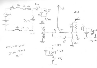
[ The ZnO TRX is a minimalist 80m band transceiver with a homemade tunnel-detector-diode as the only active device – based on Nyle’s K7NS experimentshttp://sparkbangbuzz.com/zinc-osc-2/zinc-osc3.htm – please find attached an early schematic ]
Three days in a row after Xmas I tried for several hours each, I had announced the activity on QRPSPOTS and the German QRP Forum. Thus several guys within the right distance were really trying hard to copy. I used different temporary antennas, mostly verticals, but also a sloper dipole – nada, niente , nothing. One or two OMs reported weak CW signals on the scheduled QRG, but too deep in the noise, to even make out, whether it was me or someone else.
Yes, power is more or less comparable, actually it’s 0.5mW +/-3dB depending on the day’s form of the homemade tunnel-detector, but I guess all my antennas are some dB behind a full-size dipole, so at the end it’s pretty much the same.
Folks were very cooperative during the test itself, but after it was clear, that it had not worked, the usual trolls showed up to explain, why that never could have worked… I plan another test within the coming week e.g. during the PA-contest next weekend ( I’m only 30km from the dutch border ) with a base loaded 15m vertical – be assured, you’re the first to hear about any success in terms of QSO or just being heard anywhere.
What would we go for, if everything works as expected and/or right from the beginning – or as Jim said it : What fun…
73!
Peter/DL3PB
Finally, Alan Wolke provides a very illuminating (as always) explanation of tunnel diodes):
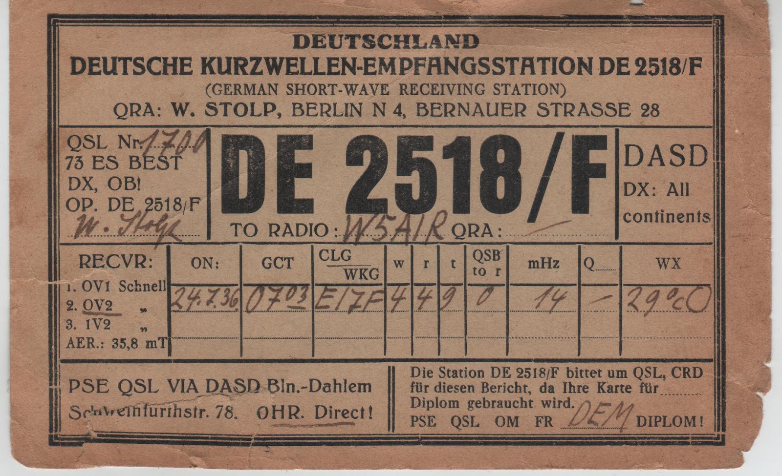
I found this today while rummaging around in the shack. It is starting to fall apart so I figured I better digitize it before it turns into dust.
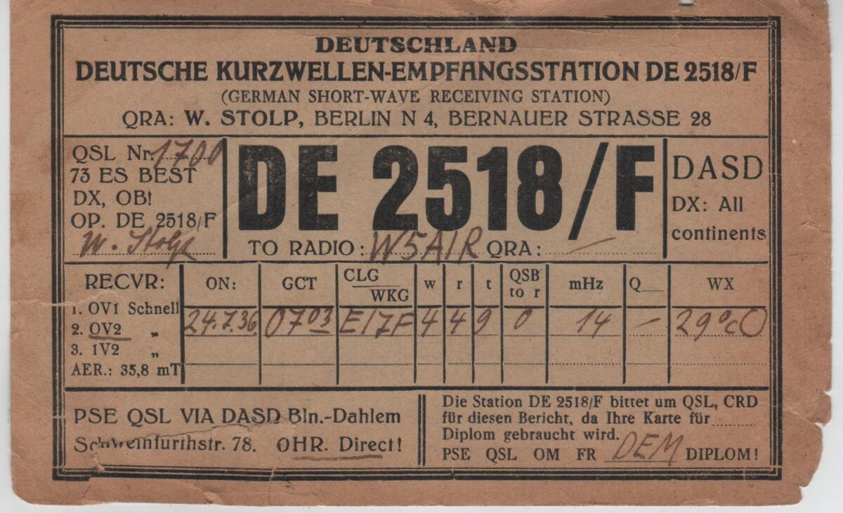
July 24, 1936. 7 am in Central Germany. 29.0 degrees Centigrade. Clear skies? German Shortwave Receiving Station DE 2518/F monitored W5AIR’s contact with Irish station EI7F on 20 meter CW. The receiver was an OV2 Schnell tube (almost certainly a regen) fed by a 38.5 meter long antenna.
Conditions must have been pretty good — they were approaching the peak of sunspot cycle 17.
In 1954 W5AIR was assigned to Garold D. Sears. He was probably the operator.
I found this today while rummaging around in the shack. It is starting to fall apart so I figured I better digitize it before it turns into dust.
July 24, 1936. 7 am in Central Germany. 29.0 degrees Centigrade. Clear skies? German Shortwave Receiving Station DE 2518/F monitored W5AIR’s contact with Irish station EI7F on 20 meter CW. The receiver was an OV2 Schnell tube (almost certainly a regen) fed by a 38.5 meter long antenna.
Conditions must have been pretty good — they were approaching the peak of sunspot cycle 17.
In 1954 W5AIR was assigned to Garold D. Sears. He was probably the operator.
Michael DF2OK has been melting solder in Germany. Above is a short video of the first sounds made by an AC-1 replica he built. Michael notes: “Yeah, I love these old style radios. You can see nearly everything. 🙂 BTW: All without Arduino and other black boxes and chips!” FB Michael.
During the AC-1 build Michael struggled with a bad tube. His discovery and resolution of the problem is presented in this video (understandable even to those who don’t speak German):
Finally, here is a nice video of Michael’s 40 meter regen receiver. Anyone who has built or worked with a regen will understand perfectly this video. Watch Michael tune in stations while adjusting the regeneration. Note his demonstration of the lack of hand capacitance. FB Michael! Thanks!
A video about the Kon-Tiki expedition got us wondering about how you could generate hydrogen gas for an antenna balloon while on a raft at sea. (That’s the kind of question that keeps Knack victims up at night.) This led us to the Gibson Girl rescue radio. This morning I found a fascinating web site that gives the long, multi-country history of the curvaceous rescue rig:
A video about the Kon-Tiki expedition got us wondering about how you could generate hydrogen gas for an antenna balloon while on a raft at sea. (That’s the kind of question that keeps Knack victims up at night.) This led us to the Gibson Girl rescue radio. This morning I found a fascinating web site that gives the long, multi-country history of the curvaceous rescue rig:
Excellent Lucien! Thanks for sending this. I know what you mean about a project that doesn’t work. It is rewarding and educational to figure out where you went wrong. I knew a guy who would ask, at a hamfest, “Does this rig work?” If the the seller admitted that it didn’t, he’d reply, “Good, I pay extra for that!” He liked the challenge of fixing it. Of course, there are limits to this, and sometimes these challenges will make you wish you had taken up stamp collecting.
Hi Bill and Pete,
For me too, it’s a happy day – I got the Mighty Mite working! Thank you so much for the inspiration to get into homebrewing…
I’m just licensed for a year now and this was my very first project (except for 2 basic kits that I build) and it really was a great learning experience. The best part: Since it didn’t work out “plug’n play”, I had to debug the thing and actually start thinking – so I put 2 caps in parallel instead of the wrong one I had used (I found them in a little box some guys at a hamfest gave me for free – never thought I would ever use something from it…). And I had to use the voltmeter to look for a short circuit. Basic stuff, but for me, this was a breakthrough!
Here are some more things I learned during this first project (don’t laugh):
Where the heck do I plug stuff that’s supposed to go to “ground” in? Now I know: usually to the negative pole!
When 2 lines cross in a schematic, that doesn’t mean there’s a connection!
How do these ready-made breadboards actually work? Had to try out…
It’s important to think about the actual layout beforehand!
When debugging, trial and error doesn’t help.
There’s yet another crazy foreign unit called “gauge”! (I used smaller magnet wire than recommended, it still seems to work…)
9V-blocks get VERY hot when shorted for a minute or so!
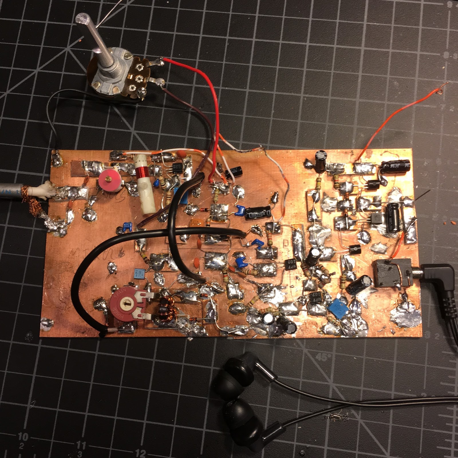
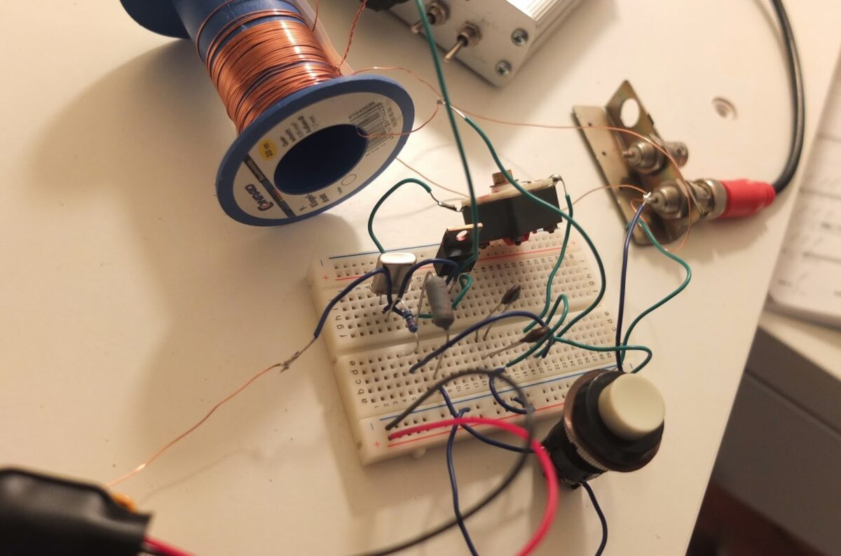
Attached is an image of my ugly prototype, now I want to give it a better “home”… And here is a little video, demonstrating that it works, inspired by IZ1KSW:
I love this video. Colin finished his BITX a week or so ago and has been waiting for an opportunity to test it. Over the weekend he braved the winter of Northern England and, with his son, set up his new rig out in his snow-covered garden. Appropriately for a first contact with scratch-built rig, the circuitry was unencumbered by any kind of case or box. That’s the way it should be done! Well done Colin! You are well and truly a member of the International Brotherhood of Electronic Wizards, and the diagnosis of “The Knack” has been confirmed (a severe case, it appears).
Hi Pete and Bill,
It’s been a lovely fine day here in West Yorkshire, so I took a table out into the garden and set up my BITX circuit on it. I set up my SOTA dipole on a 9m fishing pole.
I heard a strong German station calling CQ, so I gave him a call and hoped for the best!
How amazing to contact someone in another country using a rig and mic you’ve made yourself! Do I qualify as a REAL radio ham now? Do I have a confirmed case of the knack? 🙂
Although I may appear underwhelmed in the video, (besides the air punches!), I did really get a kick out of the QSO.
73 and huge thanks to both of you for the encouragement and support.
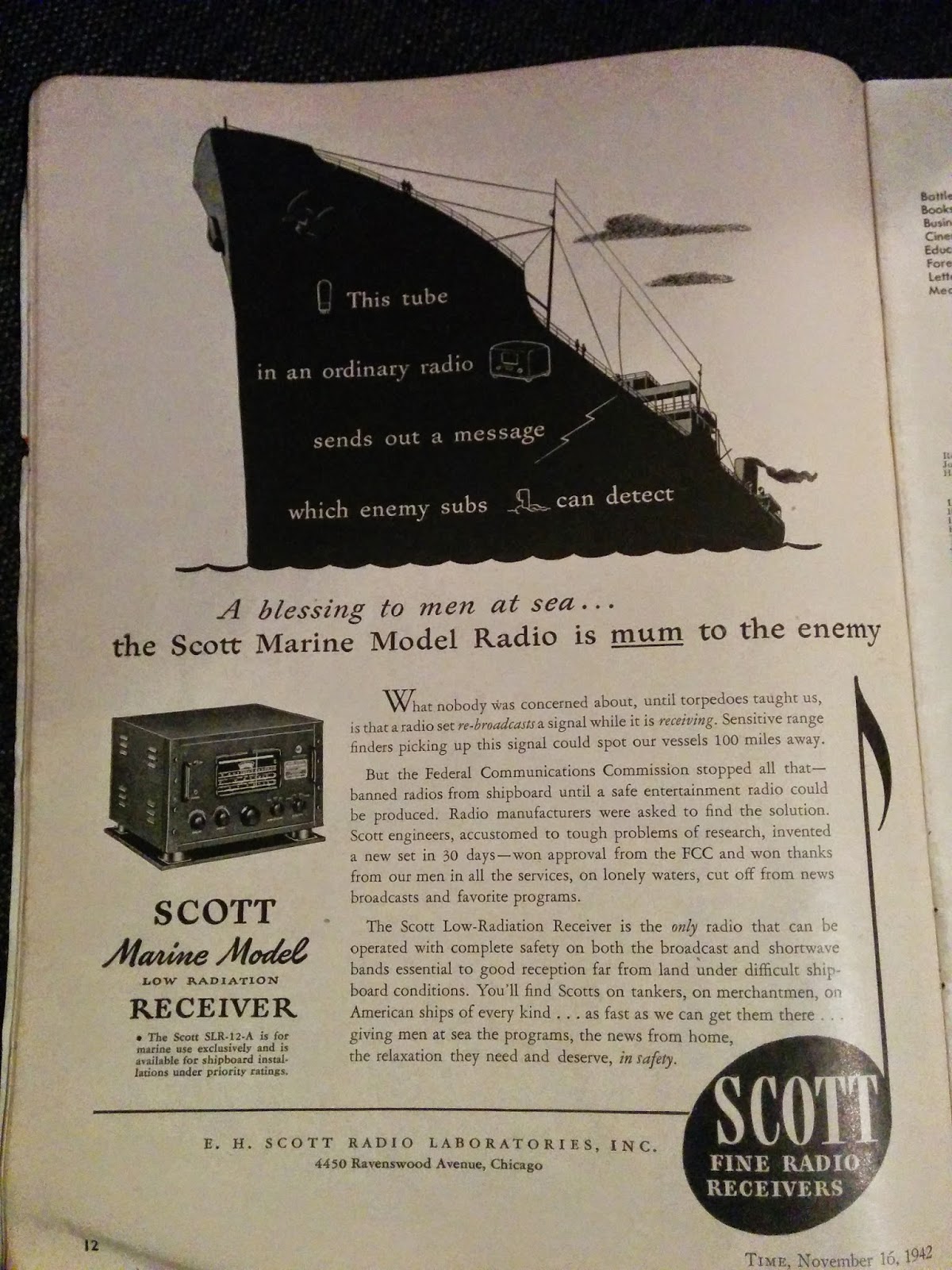
Thomas KK6AHT is the intrepid radio amateur from France who moved to California and successfully built a Minima as his first homebrew project. Yesterday we got additional evidence that Thomas definitely has THE KNACK. It seems that he has been looking through really old radio magazines (clearly a symptom). He sent us this add from 1942. Yikes! Imagine getting your ship sunk because your Local Oscillator is not quite local enough!
…………………
Hey!
I thought you would get a kick out of this 1942 ad. Sounds like those guys had a some good reasons to fight QRM … Who knew the important role played by the FCC during the war?
Now tell me: why were the receivers so noisy at the beginning of the war? What did they change? Happy new year to you both! May the gods of radio (and digital) bring you much fun on the air.
73, Thomas
…………………………
Good to hear from you Thomas. Long time no hear — I was beginning to fear that you had grown disillusioned with homebrewing and had switched to stamp collecting or something else less frustrating.
As for the ship radios, two things come to mind. Some of them may still have been using regens at the start of the war. If so, that was kind of suicidal — regens radiate! The detector moves in and out of oscillation (sometimes staying in oscillation) at the receive freq. The Germans were quite good at detecting and direction-finding these signals, on land and at sea. So the regens would have to go.
Superhets are not quite as bad, but they too can radiate. My Bitx spills out a bit of signal at 23 MHz (VFO) and at 5 MHz (BFO). Without adequate shielding, these sigs could also be detected and triangulated. Looks like the radio in the picture had lots of shielding.
We watched a French movie last night: The French Minister. A comedy about life in the French Foreign Ministry. It was kind of fun.
What are you working on? I am listening to 17 meters using an OLD superhet in which I have replaced the VFO with an Arduino/DDS generator. Works great but the display is making lots of noise.
73 Bill
…………………………….
Hi Thomas,
Well Thomas, I will dip my toe into some very deep water and attempt an answer for you which also is an important clue about QRP operations.
Today we have many many signals co-existing in the radio spectrum. During the war there was much less radio garbage and the military lit up the ether with transmissions very sparingly. But that is on the transmit side. That said the local oscillators (much like you have with the Si-570 on your Minima) used in receivers also produce RF that unless is minimized in some fashion is passed right through to the antenna and can be detected. Regenerative receivers are especially prone to this. Yes some military equipment used regenerative receivers. In fact the famous Paraset had to be constantly moved so it would not be detected.
This receiver generated RF into the antenna was addressed by companies like Scott by shielding everything. That receiver in the photo probably weighed about a 100 pounds or more. Much attention was paid to RF bypassing and grounding. The cheap table top radios were RF generators par excellence.
There was another approach developed in WWII to solve that problem and forms the basis of what makes work that little device sitting in your pocket. The odd part it was invented by a famous movie star. Look up Heddy Lamar in wikipedia. She and a co-inventor came up with the concept of frequency hopping and spread spectrum technology. By jumping frequencies it would be hard to pinpoint a transmitting station. That concept forms the backbone of our cellphone system
Now the QRP part – if the RF output from a receiver local oscillator (milliwatts) can be detected from afar – then it follows QRP works!
Bob LeDoux sent us a link to a really amazing site about the Hellschreiber system. The site is filled with great videos, pictures, and animations like the one above. Lots of radio history too. Check it out: http://www.nonstopsystems.com/radio/hellschreiber-function-operation.htm This is all the work of F. Dorenberg, N4SPP. Thanks OM!
Bob writes: I’m working on a microcontroller based reader for this mode. For old fossils, like us, this mode looks perfect. It can be sent using simple CW equipment and it appears to be a great replacement for those who are tiring of Morse code. Its perfect for Knack victims. We can even build mechanical printers. Thanks Bob!