
Category: Filters
First Signals from the “Armand HROish” Receiver

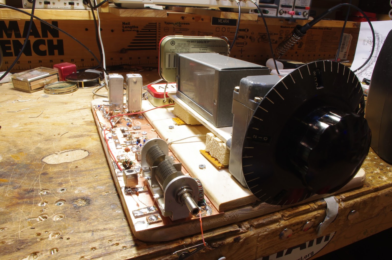
I’ve been kind of busy lately with other things, but I have managed to squeeze in a few minutes most days to work on my latest receiver project. I call it the Armand HROish receiver. Armand WA1UQO sent me the big National HRO-style dial and gear box, and he was there at the Manassas hamfest when I bought the dual variable cap that now serves in the front end pre-selector.
I went with a 455 kHz IF. The idea is to have a receiver that tunes from around 6.5 MHz to around 8 MHz so I can do some shortwave listening AND listen to 40 meters.
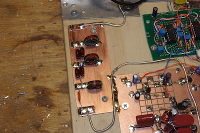
So far the filter consists of three IF cans (one small transistor can and two larger tube-type cans). The small transistor can was given to me by Michael Rainey AA1TJ – thanks Mike. Doug DeMaw suggested this use of IF transformers in his “Design Notebook.”
At the front end I have a tunable dual tuned circuit filter followed by a 40673 amp.
The mixer is an SBL-1.
1st and 2nd IF amps are a 23 db 50 ohm termination insensitive amplifiers.
I have a second SBL-1 that will be the product detector, but I haven’t built the BFO yet. So today I hooked up two 1N34A diodes in voltage double config and — with a bit of AF amplification, got the receiver inhaling with a diode detector. I could pick up Radio Canada. Then I heard SSB sigs on 40. With no BFO, I decided to put my sig gen on 455 kHz and just wrap the lead around the IF cans. It worked — I could listen to SSB and CW sigs. Very satisfying.
Still to do:
— BFO and product detector.
— Work on AF amp.
— Get my CM-455 crystal mechanical amp in there with some relays around it so I can switch from narrow to broad via the front panel.
Lots of soul in this receiver: All parts either 1) came out of the junkbox, 2) were gifts from friends, or 3) were recent hamfest purchases. The HRO dial from Armand and the IF can from AA1TJ. The 455 kHz filter idea came from Doug DeMaw, the VFO circuit from SSDRA. The VFO base is from Whole Foods and the whole thing is built on a kitchen cutting board. It includes a 40673 and germanium diodes. The VFO amps are in Altoid tins. It will, when finished, go into a big metal box given to me by Tim KI6BGE and shipped east by Pete Juliano. And when I was working on the 1st mixer, I accidentally pricked my finger and a drop of N2CQR blood went onto the breadboard. Of course, I left it there. SOUL!
The Radio Gods are apparently pleased: In the first hour or so of listening, I was rewarded for my efforts when I managed to hear Tim WA1HLR on 40 AM describe his troubleshooting of an old piece of gear. TRGHS.
Update on the PA3GSV M4MMRX — And a Mystery
Note the establishment of a new acronym (M4MMRX) for Lew McCoy’s Mate for the Mighty Midget receiver. We have needed this acronym for a long time, and SolderSmoke HQ is proud to have come up with it. We do our part my friends.
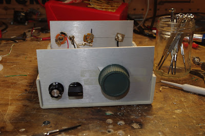
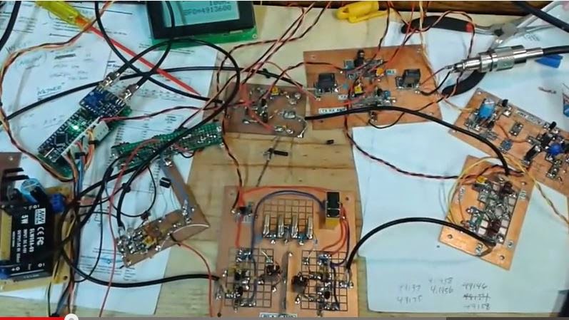
Jan has made more progress on his amazing Dutch M4MMRX and has produced a short video showing the receiver in action with SSB and CW signals.
Here is a bit of intriguing homebrew mystery: Jan has gone to a LOT of trouble to create that semi-circular opening in the center of the front panel. He even cut a corresponding semi-circular hole in the sewer pipe cap that serves as the large wheel in his amazing homebrew reduction drive. But he won’t tell us what he plans to do with that space. So I ask you, dear SolderSmoke readers: What is that space for? Why the see-through panel and sewer-pipe cap? What is Jan’s plan?
From Jan:
Hi Bill,
The rattle is gone, so I made a little video of the MMMRX in ssb and cw mode.
In the text, a ch327 and a ch45 crystal is mentioned, but I can’t get this to work.
The ch45 has a 453.6 kHz fundamental, for ch327 can’t find one.
The ch327 is a FT-243 one, tested several, but no fundamental somewhere around 455 kHz.
For ssb there is a ch45 and a ch46 crystal in, which should provide a bandwidth of about 2kHz.
(Still not totally in the clear how this should work with the very narrow resonance response of the crystals.
One should expect two peaks and nothing in the middle?)
For cw I found two ch45 crystals about 130 Hz difference in frequency, which seems to work well.
Still need to correct the 40m oscillator coil, then move on to finishing the receiver.
This is my first home brew tube superhet.
The project isn’t finished yet, but it sure is fun to build, and learned a lot during the process.
73 Jan
A Lot of Soul in the Barbados Receiver
After a rather frustrating period working on the Hallicrafters S38-E, I decided to do something different, maybe work on something that isn’t known as a “widow maker.” So pulled off the shelf an old Doug DeMaw Barbados Superhet Receiver. “Barbados” sounds much nicer than “widow maker.” This design and this particular receiver have quite a history:
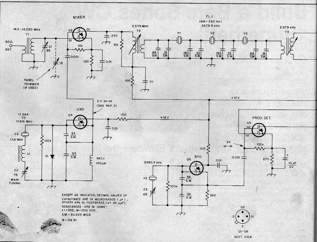
— DeMaw presented the receiver in the June 1982 issue of QST. It uses six 40673 dual gate MOSFETS, an op amp for the audio, and a 250 Hz crystal lattice filter at 3.579 MHz using (YES!) colorburst crystals. The local oscillator was a VXO. Doug’s was for 20 meters, but his article provided a lot of info on how to put it on other bands.
— I built one in 1997, building it for 20 CW. That project is described here:
— Sometime around 2000 I bought another one. This one had been built on a FAR Circuits board by Dale Parfitt, W4OP. Dale had used 5 MHz rocks for the filter and had used a varactor tuned circuit for the LO (with a DC-DC converter to increase the range). I put it aside. It sat on shelves in several countries for a number of years. (I even have a THIRD one, a partially stuffed board that Michael Hopkins (the guy who wrote those great stories about Frank Jones coming back to life to retake the 5 meter band)).
— I started working on it again around 2005. We were in London by then. I put it on 17 meters using a capacitor-tuned VXO running up at around 23 MHz. I did a quick and dirty broadening of the crystal filter by simply changing the capacitor values in the filter. This worked, but obviously it needed refinement. As I asked questions about this receiver, Dale Parfitt came to my rescue. It took us both a while to realize that he was advising me on the receiver that he had built. That was kind of cool.
— I used the receiver with my first homebrew SSB transmitter. I had them both running with separate VXO’s, with crystals switched from the front panels. I’m sure there were no other rigs like this on the air anywhere in the world.
— By 2011 we were back in the US and I put my old homebrew SSB station back on the air.
— In October 2014 I was building my first BITX rig. I built it for 17 meters using a 23 MHz VXO. I took the crystals out of the Barebones receiver. Later that month I used an Arduino/AD9850 DDS arrangement as a digital crystal replacement:
It worked, but it looked hideous.
— By January 2015 I had learned a lot about how to characterize crystals and build filters. I decided to take a shot at properly expanding the frequency response of the 5 MHz Barbados filter. I measured the characteristics of the crystals and got the proper cap values for a 3 kHz filter. When I tested it, the width seemed fine, but the ripple was more than I had expected. Kind of disappointed I moved on to other projects.
— Which brings us to today. Escaping from the S38-E, I decided to put the Barbados receiver on yet another band. With sunspot numbers in decline, I opted for 40. And I wanted this to be an analog, L-C VFO project. No DDS, no PLL. It would be all L and C for me, thank you! First I played around with the idea of running the VFO up at around 12 MHz, subtracting the 7 MHz sigs to get to the 5 MHz IF. But then I did a sweep of the filter. First, there was a nice surprise — the width AND the ripple were fine, just what I wanted (I must have had a measuring problem when I checked the ripple before). And the skirt was MUCH steeper on the high side than on the low side. This is why these filters are often called Lower Sideband filters. You get better opposite sideband rejection if you use them as LSB filters.
With the skirt situation in mind, I realized that running the LO at 12 MHz would not be a great idea. Our rule of thumb tells us that if we SUBTRACT the signal with the modulation from the signal without the modulation, we’ll get SIDEBAND INVERSION. So 7 MHz LSB would end up as 5 MHz USB. Not great. Plus, it is hard to get a VFO stable at 12 MHz.
So I opted to run the LO at around 2 MHz. There would be no sideband inversion, and it would be easier to get the oscillator stable. Wary of the threat of harmonics and spurs, I ran the receiver for a few days using an Arduino AD9850 at 2.125 MHz – 2.300 MHz. It worked fine.
I now have the receiver running with a real Colpitts VFO. The inductance is provided by an adjustable, shielded coil at around 1.5 uH (it was on the board) in series with a 3 uH toroid (type 6 yellow). The feedback caps are at 2200 pf with a 1020 cap in series. The main tuning cap is a small air variable with 73 pf max. This only lets me tune about 40 kHz of the band, so, in a variation on the old Main Tune — Bandspread technique, I have a rotary switch that adds capacitance in parallel with the main tuning cap. I can now tune from 7.141 to 7.300. The tuning rate is fine and I didn’t have to mess with a reduction drive.
More Barbados receiver blog posts here:
http://soldersmoke.blogspot.com/search?q=barbados
Kind of amazing that DeMaw designed this thing 34 years ago. A lot of soul in this old machine.
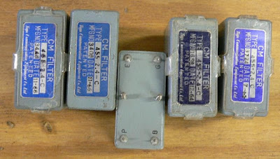
The meaning of “CM” in the Toyo CM-455 Filter
 |
| Photo by ZS1KE |
A while back I picked up (from e-bay?) a 455 kc crystal filter for use in my Lew McCoy “Mate for the Mighty Midget” receiver. I did a quick and dirty installation. It kind of worked, but I had it in the back of my mind that I had to work on the impedance matching to ensure minimum passband ripple. But when I learned what the P, B, E, and G pinout designations meant (plate, B+, earth and grid), I realized that this device had been designed with tube impedances in mind, so I probably didn’t have to mess around with input and output networks (as I’ve done with the BITX rigs). Last week I installed it as the manufacturer intended — it sounds great.
Today I started wondering about the passband characteristics of the device. What do the skirts look like? So I started Googling. There is not much out there, but I did come across a really interesting Epson site that describes the origins of this filter, and what the CM means. CM is for “Crystal Mechanical.” Wow, this little box combines the characteristics of a crystal filter AND a Collins Mechanical filter:
An excerpt:
“While at the Electrical Communication Laboratory of NTTPC, Mr. Nakazawa had had a flash of inspiration: ‘We could develop a crystal unit with a high Q factor by using the wire mount technology I’m studying now. Then, if we can achieve the idea of a mechanical filter that mechanically joins multiple units using quartz material, we should be able to develop a compact filter that achieves both excellent filter characteristics and thermal characteristics.’ Without a pause, he quickly tackled the next development issue, which resulted in the creation of the ‘crystal mechanical filter (‘CM filter’)*5). This CM filter was manufactured by processing the quartz substrate into an ‘H’-shaped filter element and functioned by using the long thin sections on the left and right sides as resonators (Figure 1). The middle portion connecting the two sides fulfilled the role of the coupler. This was precisely the ‘mechanical filter achieved using crystal (quartz)’ that Mr. Nakazawa had envisioned.
This filter was released on the market as a 455kHz intermediate frequency (IF) filter for single-sideband (SSB) modulation in radio communications. The use of quartz material meant that not only were good filter characteristics achieved, but thermal characteristics were also excellent. As this was the first filter to offer properties of this caliber, it sold extremely well throughout the world. Furthermore, this technology received the honor of being granted the Notable Invention Award from the Science and Technology Agency.”
Does anyone have the specs on these filters, and perhaps a passband graph?
Three cheers for Mr. Nakazawa!
Alan Wolke W2AEW Builds a Michigan Mighty Mite (Video)
We are honored to induct Alan Wolke W2AEW into the Colorburst Liberation Army. And for his valiant effort to build and explain a MMM Low-Pass filter, he is immediately promoted to the rank of CBLA Two Star General. Congratulations General Wolke.
As is the case with all of his videos, this one has already had an impact far and wide. Ian writes from far-off Western Australia:
Jan 27 at 6:19 PM
G’day Bill,Just in case none of your other correspondents have brought it to your attention, here is a great video W2AEW has put up showing really clearly the positive effect of a low pass filter on the output of the Michigan Mighty-Mite.
It made me appreciate the benefits of an LPF more fully. It’s always been clear to me that the harmonics would get rolled off, but in my head I hadn’t made the connection between that and the improvement to the beautiful smooth sine wave that we are working towards.
Anyway, I thought you, and your mate Steve “Snort Rosin” Smith may be interested.
Thanks to you and Pete for Soldersmoke, I’m sure you’re responsible for keeping the flame alight in many a ham.
73,
Ian VK6MIB And Steve “Snort Rosin” Smith, the guru of low pass filters, observes:
Of course, to work properly in the land down under, the inductors must be wound in the opposite direction as those in the Northern Hemisphere 😛 .
Seriously, there is a lot to be learned from the lowly Mighty Mite especially regarding impedance matching; not to mention LC circuits, link coupling, amplifiers, oscillators, etc. . What fun!
73…….SR
High-Pass Filter Knocks Down AM Broadcast Interference
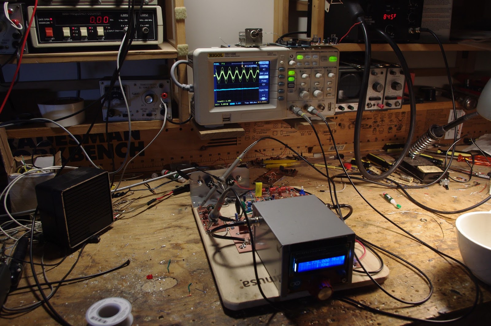
WFAX 1220 AM was starting to bother me. Each morning, I’d be drinking my coffee, listening to nice roundtables on 160 meters, when, right at 6 AM, WFAX would fire up its 5 kW AM transmitter, 1.5 miles from my location. And they would crush the “front end” of my R2 phasing receiver. It doesn’t take much to do that, since the only thing between the SBL-1 mixers in the R2 and the antenna is a signal splitter. Obviously I needed some filtering.
I turned to the free program called Elsie (L-C, get it?) and quickly whipped up a design for a seven element, capacitive input high-pass filter that promised to take about 45 db out of WFAX’s sails, without attenuating even the lowest end of Top Band.
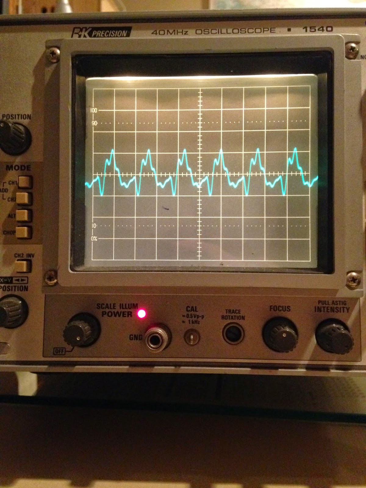
Last night I scrounged through the junk boxes and found suitable capacitors. A visit to an on-line toroid calculator showed that around 35 turns on a T-50-2 (red) iron powder core would yield the needed 6 uH coils. I built the filter this morning — picture below.
It works very well. You can see the results in the picture above. The yellow trace on the ‘scope shows the signal at the antenna terminal. Yikes, it shows around 4 volts rms at 1.220 MHz (the scale is 5 volts/div). The blue trace below is on the same scale — this is the signal coming out of the filter. Not enough to really measure on the 5 volts/division scale.
This was a very satisfying “quick and easy” build. I really like the sound of the R2, so much so that I’m not firing up the DX-100 as much as I had been. Instead I find myself just listening to the R2.
BITX DIGI-TIA Build Update #2 Installing and Testing Yaesu SSB Filter
Termination Insensitivity. It sounds like some sort of psychological problem, but it is not!
Our book: “SolderSmoke — Global Adventures in Wireless Electronics” http://soldersmoke.com/book.htm Our coffee mugs, T-Shirts, bumper stickers: http://www.cafepress.com/SolderSmoke Our Book Store: http://astore.amazon.com/contracross-20
N0YUD’s Mighty Mite (complete with harmonics)
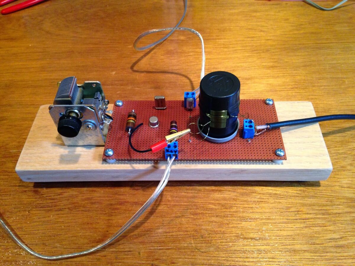

Bill N0YUD built this really nice Michigan Mighty Mite. I like the wood base (with little feet!). And the classic black 35 mm film container. And the Vero board. Fancy connectors too! Nicely done Bill.
Bill has also wisely left space for a low pass filter. As you can see in his ‘scope picture below, the MMM produces a lot of harmonics. With a low pass filter, that mess will turn into a beautiful sine wave. We’ll be talking about harmonics and low pass filters in the next podcast.
Hi Bill and Pete,
I just completed my Michigan Mighty Mite and am proud to announce it seems to be generating about 1 watt of what appears to be extremely harmonically challenged RF. I was worried about the ugly signal on my scope until I saw another screen shot on the blog page that looked almost exactly the same as mine.
What a fun project and lots to learn with just 7, or in my case 8, parts (I had to stack a couple of 56ohm resistors). I utilized those small pc board sockets for the coil and crystal so I can easily change bands and also left room for a low pass filter….
I am still struggling with the tank coil theory and impedance… Impedance matching is a very murky area for me!
I am looking forward to building the low pass filter. By the way, I checked for third and fifth harmonics and could not hear anything on my receiver. There’s another question, why does this circuit generate odd harmonics? Fun stuff, this learning game!
I love the Podcast! Thank you for your efforts and keep them coming.
’73
Bill McMillan
N0YUD
Our book: “SolderSmoke — Global Adventures in Wireless Electronics” http://soldersmoke.com/book.htm Our coffee mugs, T-Shirts, bumper stickers: http://www.cafepress.com/SolderSmoke Our Book Store: http://astore.amazon.com/contracross-20
SolderSmoke Podcast #172: Pete’s New Rig, Bill’s BITX 2040,Crystals, MMM, SNA jr.,Portable SDR, KX3!, W7ZOI at a ‘fest, BANDSWEEP!
Pete and Ben’s LBS Receiver
SolderSmoke Podcast #172 is available
http://soldersmoke.com/soldersmoke172.mp3
16 February 2015
Bench Reports:
Pete under the gun to finish SSB transceiver project. NEW VIDEO:
http://youtu.be/hbLXW0sHTFo
Bill fixes his BITX 2040 Oscillator (Bandsweep!)
Next: LP filter for 120 watt amp.
Bill’s 13 dollar Chinese freq counter (Blue! With anti-wobble tape!)
Bill’s next rig: Chipped to the Max, DDS, SBL-1s, plug in filters!
Radio Shack going under and JAN no longer making crystals.
Mighty Mite Project: Let’s get them DONE!
An easy way to get Q or ESR measurements on crystals?
SI5351 as a crystal substitute.
DuWayne’s Scalar Network Analyzer lights up the internet!
The Portable SDR rig — Pete almost goes to the dumpster!
Report from the cutting edge: Pete’s new Elecraft KX3.
MAILBAG: Meeting W7ZOI and WA7MLH at a hamfest.
Instant Messaging with Farhan
Our book: “SolderSmoke — Global Adventures in Wireless Electronics” http://soldersmoke.com/book.htm Our coffee mugs, T-Shirts, bumper stickers: http://www.cafepress.com/SolderSmoke Our Book Store: http://astore.amazon.com/contracross-20
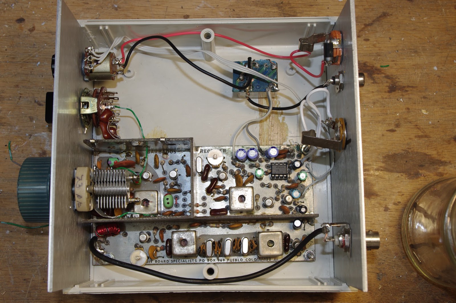
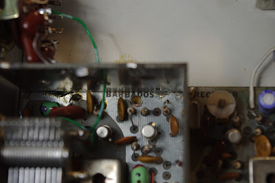
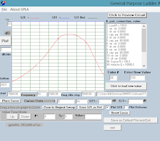
Broadening the Barebones Barbados Receiver
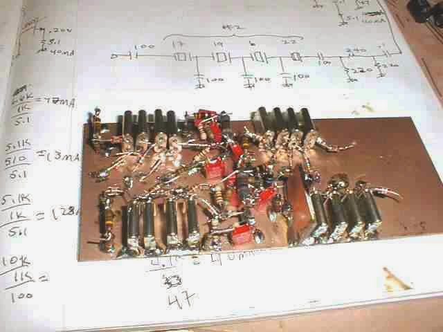
I‘ve been working on the crystal filter of the Barbados Barebones Superhet receiver. This was designed by Doug DeMaw in 1982. This one was built by Dale Parfitt W4OP and then repeatedly modified by me. It is now on 17 meters with a crystal-switchable VXO. Earlier I had made a very crude attempt to broaden the filter from its original very narrow CW configuration. This week I did this again, but this time I actually characterized the crystals and used Wes’s LDA and GPLA software (from EMRFD) to design the filter.
I played with the capacitor values and finally got the 3 kc bandwidth I wanted, but I’m having trouble getting rid of the ripple. I know this is dependent on the impedances at the two ends. The programs say I need 2000 ohms.
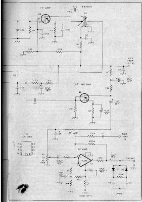
I’m kind of puzzled about how Doug DeMaw did this with his original design. For his crystals and his 250 Hz (!) bandwidth he said he needed 450 ohms. He used 4.7:1 turns ratio transformers at either end and said that by putting 10k resistors across these transformers he got the needed impedance. I can see how this would work looking into the gate of the 40673 IF amp, but looking back at the drain of the 40673 mixer, I’m not so sure that that would yield 10k. (See schematic below.)
But who am I to doubt Doug? So I assumed he was correct about the 10K and I re-wound the transformers with a 2:1 turns ratio, thinking that would get me closer to the needed 2k. But the ripple is still there. I guess I could use a return loss bridge at this point…
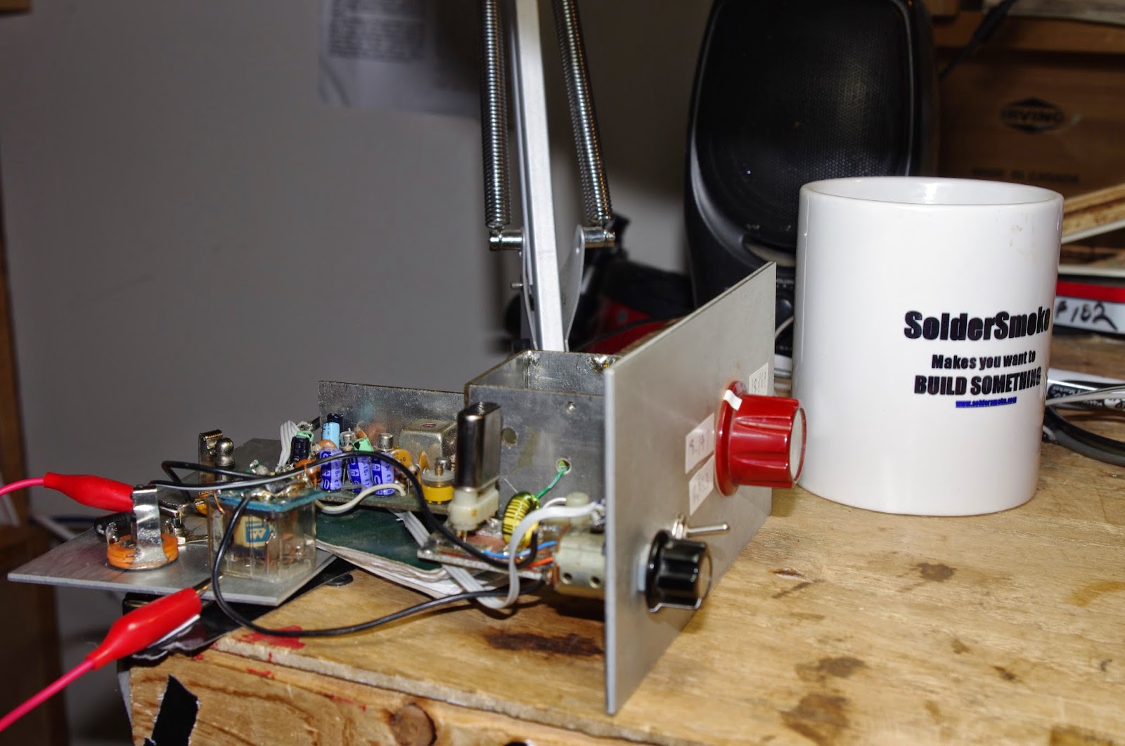
I don’t know whether this is worth messing with anymore. The receiver sounds nice. The 3kHz bandwidth gives it a nice sound, and the ripple doesn’t seem to be noticeable That FAR circuits board is tightly packed and difficult to work with. So, should I leave good enough alone, or should I proceed with fanatical ripple eradication. Any advice?
BTW: Why is it that receivers always seem to sound better when opened up (as above) on the workbench?
Our book: “SolderSmoke — Global Adventures in Wireless Electronics” http://soldersmoke.com/book.htm Our coffee mugs, T-Shirts, bumper stickers: http://www.cafepress.com/SolderSmoke Our Book Store: http://astore.amazon.com/contracross-20
Bandpass Filter Construction by Pete Juliano (video) TFMS!!!
MePads! Arduinos! Breadboards! SuperGlue! Graph paper! Noodling! Room for Relays!
TFMS (TUNE FOR MAXIMUM SMOKE!)
Another great video from N6QW. Thunder power!
Our book: “SolderSmoke — Global Adventures in Wireless Electronics” http://soldersmoke.com/book.htm Our coffee mugs, T-Shirts, bumper stickers: http://www.cafepress.com/SolderSmoke Our Book Store: http://astore.amazon.com/contracross-20
SolderSmoke Podcast #163 Pete Juliano! Tribal Knowledge Part 3 “Sideband Sidecars”
Crystal Filters built by WA7MLH
SolderSmoke Podcast #163 is available:
http://soldersmoke.com/soldersmoke163.mp3
Saturday July 26, 2014
Part III with Pete Juliano: Tribal Knowledge — Sideband Sidecars
— Moxon Update “A Thing of Beauty”
— Pete is Building Peter Parker’s Knobless Wonder
— Ladder Filters
–Construction Practices for SSB rigs
— Essential Test Gear
— Junk Box development and parts storage
Next time: Tubes, Valves, Termatrons, Firebottles.
Thanks to Bob Crane and the FDIM musicians for this episode’s musical opening.
Our book: “SolderSmoke — Global Adventures in Wireless Electronics” http://soldersmoke.com/book.htm Our coffee mugs, T-Shirts, bumper stickers: http://www.cafepress.com/SolderSmoke Our Book Store: http://astore.amazon.com/contracross-20
BITX 20/40 BUILD UPDATE #4: 11MHz SSB Ladder Filter
As reported yesterday I have the 20 meter receiver portion of my BITX 20/40 rig up and running. I decided to take a closer look at the crystal filter I built.
Here is my method:
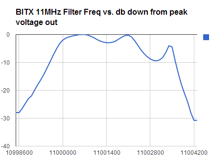
1) Using an Arduino/DDS sig generator, I put 11 Mhz energy into the base of Q2 (the stage immediately prior to the crystal filter).
2) Using my Rigol 1052E oscilloscope, I measured RMS voltage at the output of Q3/Q3A (the stage immediately following the filter).
3) I looked at Vrms as I MANUALLY varied the input frequency in 100 Hz increments.
4) I took the results and plugged them into a spreadsheet. I then used the spreadsheet to calculate the db drop from the peak Vrms value (So I wasn’t looking at insertion loss, just the filter shape).
I used 20*LOG(Vrms/276)
5) I ended up with the chart displayed above.
I have a few questions:
1) What do you folks think about my methodology for evaluating the filter?
2) Where would you guys put the BFO frequency?
3) I know the ripple looks ugly, but the receiver sounds great. Should I attempt to get rid of the ripple?
Here is the filter I used (as prescribed by the AADE software): I estimated Q at 10000 and used LM and CM values derived by the G3UUR method, and made no effort to match impedances going into the filter:
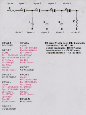
Here is what GPLA predicted. I estimated Rin and Rout values. That probably accounts for the difference between the GPLA prediction and what I measured.
Our book: “SolderSmoke — Global Adventures in Wireless Electronics” http://soldersmoke.com/book.htm Our coffee mugs, T-Shirts, bumper stickers: http://www.cafepress.com/SolderSmoke Our Book Store: http://astore.amazon.com/contracross-20
Filter Pinout: P, E, B, G Explained
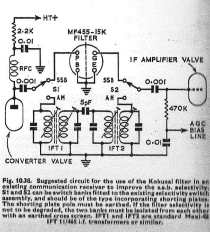
I few days ago I asked about the significance of the P, E, B, and G markings on my junkbox Toyo CM 455 kc filter (1969 vintage). PA3BCB — in yet another example of the power of the International Brotherhood of Electronic Wizards — was the first to provide the needed info. And in another example of IBEW awesomeness, KA0LDB noted that the markings are explained in the 1971 RSGB Handbook.
P = Plate = filter input
B = B+ = mixer B+ plus if needed or input ground
G = Grid = filter output
E = Earth = Ground
I like the switched filter arrangement presented above (from the RSGB Handbook); the 2.4 kc bandwidth is great for SSB, but a little tight for AM. I might put in a DPDT switch in the circuit so as to be able to go back to the “broad as a barn door” selectivity provided by just the 455 kc IF cans.
Our book: “SolderSmoke — Global Adventures in Wireless Electronics” http://soldersmoke.com/book.htm Our coffee mugs, T-Shirts, bumper stickers: http://www.cafepress.com/SolderSmoke Our Book Store: http://astore.amazon.com/contracross-20