Switching to a Mechanical Filter from 1967 for my HRO-ish Receiver (with video)

From RSGB Handbook 1982


Having overcome the difficulties with the National NPW Dial and Gearbox, I turned my attention to the 455 kHz filter. I had been using this old Toyo CM – 455 kc filter (Date stamped August 1969). CM stands for “Crystal-Mechanical.” These filters are hybrid with some of the features of a crystal filter and some of the features of a mechanical filter. For more details go here:
https://soldersmoke.blogspot.com/2016/04/the-meaning-of-cm-in-toyo-cm-455-filter.html

I was disappointed by the CM filter. It seemed very lossey, and it just didn’t seem to be of sufficiently high Q — it seemed very broad. I could hear the other side of zero beat. It was barely a “single signal” receiver, and being “single signal” is the whole point of a superhet.

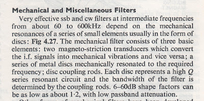
I remembered that Pete Juliano had sent me a Japanese-made 455 kc mechanical filter. Maybe this would do better. Last night I did a quick comparison test and — wow — Pete’s filter was much better. The Fifth Edition of the RSGB Handbook seems to agree with my assessment, noting that mechanical resonator filters were superior to the Crystal Mechanical hybrids (see pages 4.17 and 4.18)

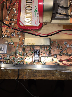
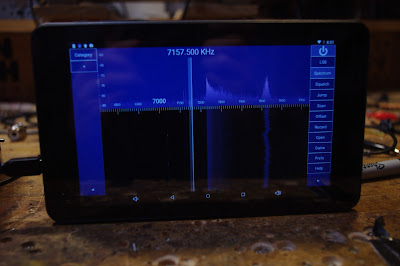
Pete’s filter is from the Kokusai Electric Company. Part# MF 455 ZL. (Date stamped May 1967). “ZL”indicates lower sideband. I checked and indeed the passband goes from just above 452 kc up to about 454.5 kc. This is a 40 meter receiver and SSB on 40 is LSB, so this filter would work perfectly right? Not so fast! Sideband inversion had to be considered.

I was running my VFO from about 7455 to 7755 kHz. This means that the modulated incoming signal would be SUBTRACTED FROM the VFO signal to get to the 455 kHZ IF. And when that knd of subtraction happens, we have sideband inversion. The LSB signal will look like a USB signal when it reaches the filter.

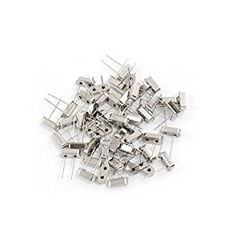
My BFO was running right at 455 kHz, using a ceramic resonator at that frequency. I briefly considered just shifting it down to 452 kHz, but this proved to be difficult. Then I got a better idea.

I could just shift the VFO down to 6545 to 6845 kHz. This would mean that the VFO frequency would be subtracted from the incoming modulated frequency. There would be no sideband inversion. I had been thinking about doing this frequency shift anyway, thinking that VFO stability gets better as you go lower in frequency.

REMEMBER THE RULE: If you are subtracting the modulated (signal) frequency from the frequency of the local oscillator or VFO, only then will you have sideband inversion. See:
https://soldersmoke.blogspot.com/2015/05/sideband-inversion.html

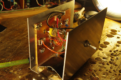
Moving the VFO was easy. I am using a variable capacitor with several variable caps on the same rotor. I just moved from the smallest variable cap to the middle variable cap — this added capacitance to the system and lowered the frequency. I also added three additional turns on the coil. This put me very close to where I needed the frequency to be. I added one additional 9 pf cap and this put the VFO freq right where I wanted it.

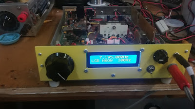
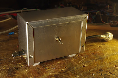
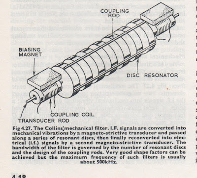
I was really glad to include Pete’s filter in this receiver. The mechanical resonator technology fits very well with the very mechanical old-tech theme of this project (it already had a gearbox — a mechanical filter seemed to fit right in). It is a fascinating device — it is almost like having a set of tuning forks all tuned to 455 kc (see above for the RSGB description of how it works). And having it from from Pete adds a TREMENDOUS amount of mojo, juju, and soul to the new machine.

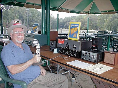
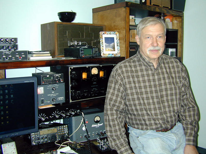
Icing on the cake: As I type this, I am listening to Fred K3ZO converse in Spanish with hams all through South America. Fred preceded me by three decades at the U.S. Embassy in Santo Domingo, but when I got there the local hams were still talking about him — he was much loved and admired by the Dominican hams. TRGHS. See Fred’s story here (scroll down a bit): http://www.gadgeteer.us/DRDISP.HTM

SolderSmoke Podcast #203 Winter, Transceivers, Antennas, DC RX, uBITX, Mixers, ‘fests, MAILBAG

N6QW in 1959. Building an SSB transceiver

SolderSmoke Pocast #203 is (FINALLY!) available:

http://soldersmoke.com/soldersmoke203.mp3


24 March 2018

–The reasons for our delay.
Winter, Computers, College, Family Trees, Lawyers….

— Winterfest 2018
— Pete launches 2018 THE YEAR OF THE TRANSCEIVER
http://n6qw.blogspot.com/
— SDR – Satan’s Digital Radio?
— Direct Conversion Receiver Projects
— Mixer Musings
— A Thailand Troubleshoot
— Nor’Easter knocks out Bill’s Moxon — An appliance replacement?
— Homebrew Electret Mics. Seriously.
— uBITX Build with Rogier
— Civilized Crystal Testing
— Baofeng!
— DRAGNET

— MAILBAG
KD4PBJ’s REGEN
N6ORS’s SDR rig
Mike Rainey’s DX-100

SolderSmoke Podcast #198 – D-104, HW-8, Juliello, DIFX, Dishal, Baofeng, MAILBAG

Bill Breshears WC3K (SK)
SolderSmoke Podcast #198 is available.


29 July 2017

Sign on a beach store: SHACK-TACULAR!

Noticed that EB63 amp was getting hot. Why?
TT2, Herring Aid5, Farhan’s Key: QRPp and CW! See?
D-104 lore — Reading from Bill Breshear’s (WC3K) ER article
Astatic crystal/ceramic element — disappointingly flimsy
Electret-ing it. The G-Spot (see picture above)
Walery KB2FIV sent crystal mic element and piezo buzzer (reverse for mic!) FB
HW-8 AF filter Center Frequency Problem. IT’S TRUE! Fixed! Finally.
Shack re-org at N2CQR
Got Steve Silverman’s HP 8640B Sig gen on the bench. Required reinforcement
Pete’s new DIFX
LM373 rigs. Perhaps with that CA3020 Pete sent me. Chips Ahoy!
Juliano Yellow? Origins of Blue? Juliello? Julionyx?
HB Crystal Filter Capitulation? Don’t give up Pete — just dish the Dishal!
Ceramic VXOs? K.P.S. Kang
Crystal testers by G7WKE and Dino KL0S. Impressive.

Antennas and BITX40 modules. Antennas are important.
Bill’s new Baofeng HT on 440.
Fixing my Sony SW7600GR
MAILBAG
Steve Silverman alerts us to NYC radio row now in the Bronx.
Tony G4WIF on the cover of SPRAT — Getting the Don Cameron award. FB
Armand WA1UQO points out that the Berryville hamfest is coming up…
Thomas KK6AHT F4HDQ writes in.
On the air with W8NSA

Juliello. No.

Dino’s FB W1FB Crystal Tester

A couple of weeks ago I noted that the complexity of DeMaw’s circuit caused many of us to wimp out on this test gear project. I joked that those who had built the device might be able to set up small businesses to do the testing for the rest of us. Perhaps our friend Dino can cut a deal with G7WKE to divide up the world market for crystal testing: Dino could have the Western Hemisphere while Rob covers Europe and points East.

Bill –

Enjoyed seeing someone else who has built Doug’s crystal tester on the blog. Here’s mine, built this back in early 2007. Anyone who wants to duplicate the tester can find the article in the January 1990 issue of QST or the updated article in the W1FB Design Notebook (page 192). Note that the QST article has a missing component value and a missing component (both corrected in the Design Notebook):


(1) R24 is missing its value – it’s marked in the Notebook as 56 ohms.

(2) There should be a 220 ohm resistor connected between the output pin of U2 the LM317T regulator and the top of R1 the voltage adjust pot that is connected between U2’s adjust pin and ground [corrected in the March 1990 QST Feedback column].

I built a FT-243 adapter to let me work with larger crystals.

73 – Dino KL0S


G7WKE’s Crystal Tester

Wow, this is an example of dedication to the cause. I think many of us wimped out when confronted with the complex circuitry of the test device prescribed by DeMaw, but Rob G7WKE actually built the thing, and did a great job on it. I’m tempted to suggest that Rob might want to set up a small business leasing this rig out to less dedicated filter builders. Or perhaps he could have batches of crystals sent to him for DeMaw-ian analysis.

Hi Bill,
After listening to you and Pete discussing crystal filter design during SolderSmoke 197, I thought you might be interested in my latest project.

This is the Crystal Tester from January 1990 QST that is reprinted in W1FB’s Design Notebook, which I believe is the circuit you and Pete were referring to.

It all appears to function as it should, so the next step is to sit down quietly with a pile of crystals and hopefully start along the road to a working filter!

73s
Rob G7WKE.

Mod to Correct DESIGN ERROR in Heath HW-8

130k resistor inside heat shrink, across R-24
SPRAT 161 (Winter 2014/15) had a very intriguing article about the Heath HW-8 by Dave M0CEM. Dave wrote about a possible design error in the active filter of the receiver. The center frequency and gain shift significantly when you switch from “Wide” to “Narrow.” I was very interested because for many years I have noticed this problem in my own HW-8. I just left it in “Wide” and never used the more narrow filter.
Dave did some excellent circuit detective work and determined that the problem was R24. He prescribed a change: instead of 82k it should be 49.8k. The placement of a 130k resistor across the 81k R24 would have the same effect.
Yesterday morning I installed Dave’s mod. I did as he suggested and put a 130k resistor across R24. Brilliant! What a difference! In the past, I noticed a significant degradation in signal strength when I put the filter in the “Narrow” position. This doesn’t happen now — the response obviously does narrow, but the center freq stays the same.
It is really amazing to me that the Heath engineers made this error, and that it went uncorrected for so many years. There have been many, many modification articles for the HW-8 over the years, but I haven’t seen any that really address this problem.

If anyone has more info on how this design error happened and why it went uncorrected for so long, please let me know.

Thanks to Dave and SPRAT for getting us back on the straight and narrow.

Homebrew Peppermint BITX: KC1FSZ Goes Scratch-built and Sweeps a Filter

Hi Bill/Pete:


Congratulations to Bill on the award. Very well deserved!

I just watched the video that Bill made with Farhan and I really enjoyed it. As usual, lots of useful information there.

Farhan’s demo of the Sweeperino was particularly timely because this past weekend I was doing something very similar.

As I’ve mentioned to Bill before, I am working on a scratch-built BITX to accompany the Peppermint BITX-40 module rig that I’m running right now. I took Pete’s advice and started from the audio end. After building the audio amplifier, product detector, and first/last pair of IF amplifiers, I was able to connect the VFO where the BFO is supposed to go and enjoy a pretty reasonable direct conversion receiver. It works great!! My first working receiver.

So my next step was the crystal filter. I puzzled over all of the different articles, tried to follow the G3UUR method, sorted crystals, etc. and finally put the whole thing together. But all along I’ve had this doubt that I could have possibly followed all of the steps closely enough to achieve the precision needed for a 3.5 KC SSB filter – it just didn’t seem possible.

Last week I decided to try to “sweep” the filter. This was a multi-day undertaking in itself. I pieced together the microprocessor, an AD9850, a TIA amplifier, the RF power detector from the SSDRA book, and some software that generates the necessary frequency sweep and collects power readings. The picture of the test rig is included below. It’s not much to look at.

With low expectations (and wires that are too long), I ran a few seeps and then downloaded the data onto my computer for analysis. No fancy software here, I’m just using Excel. When I put the data into a line chart in Excel, what emerged from the jumble of seemingly random numbers was a thing of beauty: a 3.5 KC passband right below 12 MHz. It’s the next stage beyond the Joy of Oscillation: The Joy Of Selectivity!


It’s even showing about the right insertion loss. Note the setup is very primitive and noisy so the fact that I can’t measure anything below -8dB isn’t surprising, you can ignore that part.

But I’m starting to get the feeling that this might actually work. Onto the diode mixer …

73s,

SolderSmoke Podcast #196 Rockets, Pete’s EXPULSION, SDR, DiFX, ‘602 rigs, T.O.M.

View from rocket. I’m in front of the swing-set, with hat on. Billy to my left.

SolderSmoke Podcast #196 is available.
5 May 2017
http://soldersmoke.com/soldersmoke196.mp3

Shenandoah Rocket Launch — With video!


Pete and the QRPARCI HOF: We thank you for your support!
Note the strange seasonality of these kinds of events… Always in the Springtime…
April is the cruelest month. Especially the FIRST DAY!
Feel Tech Follow-up — the DC blocking cap issue.

HBTV? Roku Challenge?

A tube of Desitin? Why?


SDR Misadventures.

SDR on a tablet Just like WA7HRG
Pi Day More RaspPi Linux observations TOO HARD
The problem of Si5351 and updated libraries — old sketches don’t work!
My SDR question: If we go with direct sampling, no need for I and Q at front end No image problem, right? But why is there often a digital I and Q in the direct sampling receivers?
BITX MODULE
Getting RF in through the DDS jack.
Electric Radio: Reading from the history of SSB. And from the T.O.M. article
Joe Carr K4IPV : Homebrew Hero from Falls Church Va. Any more info on him?
Pete’s newest DifX
Pete’s new digital scope.
Bill’s NE602 RIG, Epiphyte History.
He put AADE crystal filter impedance match circuits in backward That’s why he needed RF amp. Duh.
The perils of a crowded box
Building RF amp board (BITX Module design) for the NE602 rig.
NE602s do not put out a lot of power. uW
BITX Module Amp circuits very stable.
Chassis as the heat sink.
Mic amp? We don’t need no stinkin’ mic amp! But yes, we do. 741 on the way.
Parts on e-bay very expensive! Back to the hamfests. On to Manassas!

Congrats to Tony Fishpool G4WIF, who received the Don Cameron, G4STT, Award for an outstanding contribution to low power amateur radio at the RSGB AGM meeting in Cardiff.


MAILBAG

Another Thermatron Receiver (video)

Thanks to Steve N8NM for sending this along. He said it seems to be crying out for a synthesized VFO — I disagree,of course.

I like the filter arrangement — one crystal at 455 kHz, two tune-able IF cans and a phasing control. This seems like a good way to get both AM selectivity (broad) while still having the ability to narrow the bandpass for SSB.

The builder did a great job. Does anyone know who he is?

N7SUR’s Nice SSB Filter — Nail Polish Stuff Adds Soul to the New Machine

That’s a beautiful graph, don’t you think? In addition to the very pleasing results, I liked Bob’s methods: the “by hand” collection of the data points using an AD9850, a ‘scope and a notepad (see below); the filing down of ceramic disc caps; the use of nail polish hardener — all this adds a definite artisanal element to this project and puts more soul in the new machine.

Like Bob, I too kind of bailed out on the Q calculation when I was doing this. But as I recall there is a variation on the G3UUR method that yields this parameter too, right?

Bill:

I’m reluctant to share this with you because the results appear too
good. I’ve attached a graph showing my four crystal, 11Mhz
filter measurements. The graphed points are read values using my
AD9850 DDS VFO feeding to a TEK scope.

A TIA amp was used for input and output of the filter. My development software was the Steder-Hardcastle software as presented in November 2009, QEX.

I am now practiced in the black art of filing off the tops of disc
ceramic caps to “adjust” their values. This black art also involves
the mysterious qualities of Sally Hansen Nail Hardener.


Let me share my method for developing the filter.

I’ve built CW filters before but this was my first effort at SSB
bandwidth which is less forgiving.

The G3UUR oscillator method (see page 3.19 in EMRFD) is a simple and
effective filter design method. but it does not provide a measure for
crystal Q, a value which impacts filter insertion loss.

So I decided to choose crystals with proven pedigree. These were 11 Mhz crystals from Mouser, part number 20-HCA1100-S. A lot of ten costs $5. These were the crystals selected by Jim Kortge, K8IQY, for use in his 2N2/20 rig.

For software, I use the Dishal package that can be downloaded from the ARRL and other sources. This package was the basis for the
Steder-Hardcastle article in November 2009, QEX. The “Xtal” pull down
menu provides entries for an individual G3UUR oscillator.

Simply put, all critical filter input values are generated by reading
the change in crystal frequency as an additional capacitor is added
into the oscillator circuit.

I suggest starting with a 4 crystal filter. Only two capacitor values
were required for my filter. Five capacitors were required–two series
and three shunt.

Start by reading the “open switch” frequency for each crystal. Sort
the crystals into increasing frequency order and choose the four with
the most narrow frequency span.

Using the pull down menu measure the individual crystal measures for
Lm, Cm, and series frequency. Average these across the four crystals.

The Lm or Cm and series frequency are placed into the Dishal software
main menu. Also enter the average Cp which is the measured capacitance across the crystal leads.

Finish up the main menu entries by entering the number of crystals (4), and the desired bandwidth–generally 2.4 to 2.9 Khz. Finally enter the acceptable ripple, which is often 0.1db.

Let the software calculate the filter values. Expect some odd
capacitance values. By changing the filter bandwidth–say from 2.4 Khz to 2.35 Khz I can move one of the capacitance values to a standard value.

The software also displays the input and output impedance. If the
filter is centered between two TIA amps, this filter impedance must be
transformed to 50 ohms in the amps. This provides the transformer
winding ratios.

The Dishal software has always given me good results. But I haven’t
compared its results to Ladpac–especially GPLA.

Bob -N7SUR


SolderSmoke Podcast 194 – Approaching the Digital-Analog Singularity

SolderSmoke 194 is available (scroll down for link)
March 4, 2017

BIG NEWS: uBITX from Farhan
BENCH REPORTS
Pete: Recycling Old Boards
Working on Arduinos and advanced displays
Bill: SDR Adventures and Misadventures.
RTL-SDR is fun. Built HB front end.
HDSDR under Windows is fun and easy.
Thought about Raspi3, 7 inch touch screen, Linux, software YUCK.
Followed advice of Ken G4IIB and got a 50 buck tablet with Google Play.
Who needs tiny OLEDs? Use a 7 inch tablet as your display!
Building a Ceramic Resonator for the HRO 455 kc filter
The value of doing something different.
Boxed up my NE602 OLED rig.
OLED noise and ACTIVE decoupling.
NE602 and MOSFET tips
LEXICON:
OTD Obsessive Tinkering Disorder G6LBQ
“A Thing of Beauty”
Source of Tombstoning term: Don ND6T.
Ken G4IIB’s extremely smooth audio.
ON THE AIR:
On AM on 75 and 40. Fun. Old Military Radio Net and “The Lonely Guy Net” on 75 Saturday morning.
Good old 17 meters. Open at mid-day
HB2HB on 40 with W0PWE.
Listening on 60
Hambrew magazines disappeared, but are back now.
EMRFD Classic Edition available
New Posts to BITX HACKS
MAILBAG:
Gloves follow-up. Not a good idea.
VK3YE’s QRP by the Bay event and a new book!
Colin M1BUU achieves Mountaingoat status
Martin A65DC JoO MMM in the UAE
Tom NY2RF Editorial with mention of JoO!
Lots of Al Fresco rigs: W8LM BITX on a board, Brad WA8WDQ DC RX, KA4KXX Al Fresco OZ DSB
ON6UU DSB from Spain via Belguim
Hugh ZL1UEM SMALL Si5351 OLED
Cookie Tin rigs VK2EMU’s Biscuit Tin DC RX, WA7HRG’s Popcorn rig
VK4FFAB FB LTSPICE intro
Ken G4IIB’s BITX adventure (with VERY smooth audio. How smooth? We can’t say.)
VU2XE’s BITX with a CAD box
G0ETP’s shockingly beautiful SDR receiver
Alan W2AEW on the mend with broken ankle. His videos are a treasure trove of tribal knowledge.

Schematic for the RTL SDR Dongle Front End

Here it is. Very simple. I used an obsolete 40673 dual gate MOSFET. I didn’t need both gates so I just soldered them together. You could probably substitute an easily obtained MPF-102 JFET. The capacitors and the coil in in the gate circuit form a parallel LC filter circuit that resonates in the 40 meter ham band. The 1 Megohm resistor maintains a very high impedance for the LC circuit, helping to maintain circuit Q (sharp response). It also drains off any charge that builds up on the gates. For the antenna input I just put 2 turns on the 4.5uH coil — this too helps maintain LC filter response. The 470 ohm resistor serves as the load and limits quiescent current through the MOSFET. It should pull about 19 milliamps — with a 9V battery that should give you around 26 hours of listening time between battery changes. That’s fine with me — I don’t use this thing that much.

Realize that I’m using this with an RTL-SDR dongle that has been given the familiar modification that allows it to use direct sampling in the HF bands. Some ideas here:
and here
and here

When Bypass Caps are Not Enough: Active Decoupling

I was having a noise problem with my NE602 Si5351 OLED display receiver. There was an annoying high pitched whine in the audio output. The source was easy to identify: If I reached in and unplugged the OLED display, the noise disappeared.

Next I had to find out how the OLED noise was getting into the rest of the receiver. It could have been through the SCL SDA or even the ground lines. It could have been just through capacitive or inductive coupling from the display board itself. A big clue came when I tried powering the display from a completely separate power supply: BINGO! The noise disappeared. So I knew the noise was going into the rest of the receiver through the Vc line that powered the OLED.

I had been powering the OLED from the 5V regulator on the Arduino Uno. In an effort to isolate the noise, I put a separate 5V regulator in the circuit for the OLED. No joy — noise still there. I then tried putting an RC low pass filter between the OLED and the 5V regulator. Still had the noise. Finally I remembered something from the AF AMP circuits of Roy Lewallen, Rick Campbell and Roger Hayward. ( I think Roy was the pioneer on this one.) They all used an “active decoupler” between the first AF amp and the power supply line. I confirmed that it was my first AF amp that was picking up the OLED noise. I built the active decoupler (just three parts!) and the noise disappeared. GONE!

There are only three parts, but the way this circuit works is kind of complicated and not very intuitive. There is a good discussion of how it works here:

www.facstaff.bucknell.edu/dkelley/elec351/Lab/elec351lab5_sp04.doc

Roy, Rick and Roger were using this circuit to knock down 60 Hz AC hum, but I found that my OLED noise was at around 200 Hz — I figured (correctly) that the active decoupler would take care of this as well. I think this little circuit can be useful in dealing with the kind of noise generated by the digi displays that many of us are now using.

David Rowe has a really interesting analysis of this circuit here:
http://www.rowetel.com/?p=4781

Of Waterfalls, SDRs, and Homebrew Analog Rigs: Words of Wisdom from W8JI

W8JI


It happened again today. Conditions were good and I was BOOMING into the NYC area on 40 meters. 40 over. Everyone liked the signal and said it sounded great. Except for one anonymous grump who chimed in to say that I was “9 kc wide.” I imagine he was basing this on a quick look at his super-dooper SDR waterfall, without any consideration of signal strength or the characteristics of his own receiver. Sigh. The Waterfall Police had struck again.

OM W8JI gives a great description of the pitfalls of this kind of “you’re-too-wide-because-my waterfall-says-so” reasoning. Check it out. And keep it handy in preparation for your next encounter with the 40 meter Waterfall Police.

https://www.w8ji.com/checking_bandwidth_with_receiver.htm

A Charming Detail About the BITX40 Module

In the BITX20 yahoo group, Farhan responded to a question about the BFO and the crystal filter in the BITX 40 Modules. In his response we learn more about the work of the members of the women’s collective. Uma is the name of the lady who has the job of sorting the crystals. She sorts 1000 a day:

Farhan writes:
There is a longer explanation to this. The crystals we use in the BITX are microprocessor grade. This means that they are not very precise. Uma is the crystal sorter. She takes a bunch of 1000 crystals a day and sorts them by their frequency into different bags. Each board takes its five crystals from any one bag. Hence, the central frequency of each board will be slightly different from another board.

The central frequency of the ladder filter moves down from the oscillating frequency of the same crystal. That is why, in a set of matched crystals, one can be directly used as the carrier/beat frequency oscillator without needing any trimmer : it directly sits on the higher side skirt of the filter.

The BITX40 board’s BFO usually ranges from 11.990.0 to 11.997.0, though in almost all cases it is very close to 11.998.0. The best way to determine the BFO frequency is to take it another ham’s shack, tune in the BFO to zero beat on USB or LSB and note the frequency. I use the Rigol scope’s built-in frequency counter to measure it off the modulator transformer’s primary.

So, the IF offset should ideally set to the measured BFO’s frequency. These are however, very subjective choices. Given that 2.2 KHz is not an ideal passband, 3 KHz is more like it, setting the BFO will determine how you would like to hear the receiver. Setting it close to the passband will make it bassy, setting it away will make it tinny. Setting it a few hundred hertz away will make it hollow. You get to choose which way you want to make your radio sound bad (harr! harr!)

– f

Farhan on What’s New in the BITX 40 Module

Writing to the BITX e-mail group, Farhan provides some very interesting information on the philosophy behind his new BITX 40 module, and on how it differs from earlier BITX designs:
The new builders are often caught in a catch-22 : to get on air they need to build a rig from scratch. but to build a rig, they need lots of experience. A way out was to provide working boards where we can get on air quickly, and then start improving and modding the circuit. this is the spirit behind the new boards. Consider them like you would consider a raspberry pi or an arduino : simple, working circuits around which you can grow your own radio.

In the new bitx boards, I have tried to keep as close to the original bitx as I could. however, there are a few departures that I thought the bitx builders here would like to know about.


i have to admit though, strangely, i am less familiar here with bitx than many others on this form. arv, leonard, dan, andy and others have build far many more version than I did. I just happen to be the first one to build a bitx. this as much an acknowledgement of their inputs. without all you folks, bitx would not have had the kind of traction that it now enjoys. I suspect that it is the most built transceiver in the world.

So, here are the changes from the original bitx.

1. SMD
The SMD components make for virtually error free boards assembly. We used the biggest sized SMD components. In fact, the resistors and capacitors are about the same size as a quarter watt resistor that is soldered standing up. They are very easy to desolder without messing around with the desoldering wick and solder pumps. All you do is to lay the soldering iron’s bit on the component such that the flat end touches both sides at once and after a few seconds just drag the component away. I soldered the sample boards with my regular, 2 dollar, 25 watts iron without using a magnifier (I wear reading glasses).

1. 40 Meters
It is just that with the sunspots fading away, 20 meters in the tropics is far less active than before. Many of the us South Indian hams hang out on the lower end of 40 meters every morning and evening. Hence, the choice. That doesn’t mean that i can’t be converted to 20m! There are several ways to change to 20 meters. Keeping the VFO same, change the crystals (and hence the IF) to 8.833 MHz and rework the band pass and the low pass filters. I will work out the details in a few weeks and post them here.

2. A new bandpass filter
The original bandpass filter was quite lossy. I didn’t know how to use any CAD tools when i sketched it. I was actually on a long haul flight when I designed that filter. The new filter configuration is very interesting one. I saw it on PA3AKE’s site. This is a triple tuned circuit with very good out of band attenuation while maintaining very low loss.
In the last then years, ecomm has made it possible for us to globally access good quality toroids anywhere in the world. Hence, we have used T30-6 toroids with excellent low loss. I measured it at just 2 db, the original had more than 6db loss.

3. VCO
The original oscillator on the BITX used a variable capacitor. These were noisy, and often of inferior quality. In any case, they are no longer available. Instead, we have used a varactor diode for tuning. The greater benefit of using a varactor to tune the oscillator is that the tuning control only carries a DC voltage. You can install it anywhere. If you need finer tuning control, you can add a second lower value tuning pot in series with the main tuning pot. It is easier to add FLL to a VCO.

4. Audio muting
The original BITX used just a switch to move from receive to transmit. The receive voltage charged receiver’s audio preamp’s decoupling capacitor and it took time to discharge. this kept the audio preamp active even on transmit and caused a very sharp audio noise on the transmit change over. Now, the other section of the T/R relay is used to cut the audio off to the LM386 as soon as transmit line is energized.

5. A better T/R system
The original bitx didn’t have a PTT. this one has two relays to switch the linear amplification chain in and out of the circuit, mute the audio and change over the antenna. These changes lead to a very stable linear amplifier and smoother change over.

6. Mic amplifier
The original mic amplifier easily saturated. The new design, thanks to dan tayloe, has a better head room and provides very clean modulation.

7. The fixed BFO
Though the PCB has the provision for a trimmer and an inductor to pull the crystal frequency. I discovered that with five matched crystals, if you used 4 in the ladder filter, the fifth’s frequency fell right into the perfect sweet spot for LSB work. You might need to add the trimmer and an inductor back for USB work.

8. DDS connector
To use the DDS, you will have to remove L4 (the VFO inductor) and inject the DDS/PLL output into the connector provided.

There are some smaller mods that people can try out:
* The current in the receive amplifiers can be reduced if you don’t have any radio hams in your neighbourhood who run kilowatt amps.
* The capacitor between pins 1 and 8 of the LM386 can be removed if you prefer headphones to speakers.

The Last Hallicrafters Transceiver…REBORN! TWICE!

Pete Juliano and his colleague Giovanni Manzoni led me this morning to the happy land of Hallicrafters hybrid nostalgia.

It all started with Pete’s latest blog post:
http://n6qw.blogspot.com/2016/10/more-junk-box-rigs.html

I admit that I had never even heard of the Hallicrafters FPM rigs. Pete’s (uh, I mean Giovanni’s) video show’s Pete’s junk-box rebuild of the old rig. Very nice. Note the presence of the Si5351…

I needed more background info, so I turned to YouTube. This led me to more old friends: Dale Parfitt W4OP has a really nice video of his rebuild of the Halli FPM rig (see above). From his video we learn why Dr. Juliano prescribed a dose of Si5351 for the patient: Dale tells us that VFO instability was a major problem with this rig. Dale fixed his with the addition of an X-Lock board from yet another friend of SolderSmoke: Ron G4GXO of Cumbria Designs.

Dale really out-did himself by building an add-on accessory box for the FPM. Very nice. I especially liked the addition of the W3NQN passive audio filter for CW. I always have misgivings about adding audio filters to Direct Conversion receivers — this will reduce QRM, but you are still listening to both sides of zero beat. But when you add a sharp CW audio filter to an SSB superhet you will end up with true “single signal reception.” FB Dale.


Please send Pete Juliano and Giovanni Manzoni some positive feedback and words of encouragement. Please urge them to keep up the good work on the blog and the videos. Theirs is sometimes a lonely task — without feedback it can sometimes seem like putting messages in a bottle and throwing them into the digital sea. Please let them know that their work is being seen! Leave some positive comments on Pete’s blog. (No snark please — The Radio Gods will retaliate if you harsh N6QW’s mellow.)

Video: Sweeping a Filter with a FeelTech Signal Generator and a Rigol Oscilloscope

This short video shows how I used my new FeelTech Signal Generator (90 bucks shipped from China) and my trusty Rigol oscilloscope to display the passband of the filter in my Armand HROish receiver. Feedback on this test procedure would be appreciated.