
I made a cabinet out of scrap packing material. I show how I tune LC filters by squeezing the turns on toroidal inductors. I tap a heatsink and think about more power for the Mythbuster.
Category: Filters
Mythbuster Video #17 Boxing it Up, Tuning Filters, Tapping a Heat Sink, QRO Dreams….
I made a cabinet out of scrap packing material. I show how I tune LC filters by squeezing the turns on toroidal inductors. I tap a heatsink and think about more power for the Mythbuster.
Mythbuster Video #15 The Mythbuster Signal As Seen in the NA5B WebSDR
Mehmet NA5B has an excellent WedSDR receiver in Washington D.C., about 9 miles east of me. I often use it to check my signal quality. I think this video shows that the 10 pole crystal filter is working and is producing a signal with very sharp drop-off outside the 2.7 kHz passband. You should focus your attention to the passband (yellow vertical lines) near 3895 kHz. That’s me.
Once, when I was describing my 40 meter DIGI-TIA to an SDR guy, he seemed surprised that I was using a — gasp — crystal filter. “Your skirts must be atrocious!” he said. My HDR sensibilities were deeply offended.
I had hoped that the 10 pole crystal filter would produce skirts so nearly vertical as to make my signal indistinguishable (in the waterfalls) from the SDR signals. At least at this low signal level, it appears to be working.
Mythbuster Video #13 — RF Power Amplifier, and Relay Switching Plan
In this episode we enter into the most fraught part of the construction project: the production of RF power. This is where amplifiers stubbornly turn into oscillators, and where components release magic smoke, or at least burn the fingers of hopeful builders.
I kind of ran out of room when I built the low-pass filters. But, thinking ahead, I wanted to have them on a separate board. And it is good that they ended up in the far corner of the rig.
Just going from one band to two bands adds to the complexity of the rig. I had to add two relays, one to switch the low pass filters, the other to switch the bandpass filters. I ended up with 5 DPDT relays in this transceiver. It was very helpful to have a plan and a diagram for the relays and all the switching.
It looks like each of the three RF amplifier stages provides about 15 db of gain — about what I need to get to the 5 watt level.
Mythbuster Video #12 — Bandpass Filters
The really cool part comes at the end when I put the scope probe on the output, then on the input of the bandpass filter. Exciting stuff my friends!
QST Repeatedly Got Sideband Inversion Wrong
It kind of pains me to do this. These articles are from a long time ago, and the author is an esteemed Silent Key, but the myth about the origins of the USB/LSB convention is still out there, and as a homebrewer of SSB gear I feel obligated to point out these examples of the error that that myth is based on.
Last Friday, Pete WB9FLW and I were talking about homebrewing SSB rigs. I recommended a series of QST articles by Doug DeMaw. “Beginner’s Bench: The Principles and Building of SSB Gear” started in QST in September 1985. There were at least five parts — it continued until January 1986. (Links to the series appear below.) I hadn’t looked at these articles in years, but when I did, a big mistake jumped right out at me: In the first installment, on page 19, Doug makes the same mistake that he made in his Design Notebook:
“Now comes the conversion section of our SSB generator. We must move (heterodyne) the 9-MHz SSB signal to 3.75-4.0 MHz. Our balanced mixer works just as it does in a receiver. That is, we inject the mixer with two frequencies (9 MHz and 5 MHz) to produce a sum or a difference output frequency (9 – 5 = 4 MHz, or 9 +5 = 14 MHz) If we are to generate 75 meter SSB energy, we must chose the difference frequency. We could build an 20-meter SSB transmitter by selecting the sum of the mixer frequencies. The RF amplifiers and filter (FL2) that follow would then have to be designed for 14-MHz operation. In fact, many early two-band homemade SSB transmitters were built for for 75 and 20 meters in order to use this convenient frequency arrangement. The use of upper sideband on 20 meters and lower sideband on 75 meters may be the result of this frequency arrangement (the sidebands become inverted when switching from the difference to the sum frequency.) ”
Those last two sentences are incorrect. They repeat the “Myth,” or the “Urban Legend” about the origins of the LSB/USB convention. Contrary to what many hams now believe, with 9 MHz filter and a 5.2 MHz BFO it takes more than just switching from sum frequency to difference frequency to invert one of the sidebands.
There are two conditions needed for sideband inversion to take place:
1) You have to be taking the difference product (DeMaw got that right)
2) The unmodulated (VFO or LO) signal must be larger than the modulated signal. (DeMaw and the ARRL obviously missed that part. Repeatedly.)
This is another way of stating the simple, accurate and useful Hallas Rule: Sideband inversion only occurs when you are subtracting the signal with modulation FROM the signal without modulation.
For DeMaw’s claim to be correct, one of the SSB signals going into the balanced mixer would have to invert, and the other would have to not invert. Let’s see if that happens: He has the sideband signal being generated at 9 MHz and the VFO running around 5 MHz.
9 – 5 = 4 But we are not subtracting the modulated signal FROM the unmodulated signal. SO NO INVERSION
9 + 5 = 14 We are not subtracting at all. SO NO INVERSION.
Doug’s convenient frequency scheme WOULD work if he’d just switch the frequencies of the filter and the VFO. With a sideband generator on 5.2 MHz and a VFO around 9 MHz you do get the happy 75 LSB, 20 USB arrangement without the need to switch the carrier oscillator/BFO frequency. That is what happened in the Swan 240, and that is what I have in my Mythbuster rig. I am listening to both 75 LSB and 20 USB without changing the carrier oscillator/BFO frequency. My filter/BFO/product detector is set up for USB. With this arrangement the 75 meter LSB signals DO invert, and the 20 meter USB meter signals do not, so both are able to make use of my USB BFO/product detector without shifting the BFO frequency.
This error shows up again in DeMaw’s the May 1989 QST article “A Four Stage 75-meter SSB Superhet” (reprinted in the ARRL’s QRP Classics book). Here he writes:
“Should you want to cover both the 75- and 20-meter bands you can build a 20-meter version of FL-1 and band switch the two filters. As with the 75 meter only version, an IF of 9.0 MHz (Y1) is required. With this arrangement the 20 meter band will tune backwards from the 75 meter band, but upper- and lower-sideband reception will occur, as required, without changing the BFO frequency (Y2). This two band scheme with a 5-MHz VFO is an old one!” NOTE: FL1 is the bandpass filter, not the IF filter.
Doug’s mistakes in this area may simply be due to the fact that he was more of a CW guy. And this is something that is quite easy to confuse: 9 and 5 will get you to 75 and 20, but you have to make sure the VFO is at 9 if you want to make use of sideband inversion and avoid having to shift the BFO/ carrier oscillator. I’ve made this mistake myself:
In October 1993 I wrote to DeMaw about his Four Stage 75 meter SSB Superhet. I think I was looking for details on how to put it on 20 meters. As I recall, Doug wrote back telling me to just pick 20 meter values for the input bandpass filter. Had I done so, I would have discovered that — for the reasons cited above — this just wouldn’t have worked on 20. His BFO and filter were set up to receive LSB signals. That’s fine for the incoming 75 meter LSB signals. But on 20 — contrary to DeMaw’s thinking — there would be NO sideband inversion. I’d be trying to listen to 20 meter USB signals with a receiver set up for 20 meter LSB.
Did anyone else notice these errors. Were there ever errata notices in QST on this?
This is a reminder that you should take all technical articles and schematics with a grain of salt. Many contain errors. We are all human, and this is a complicated subject with lots of details.
Mythbuster Videos 8 and 9 — The Old Military Radio Net plus “Zero Beat and The Vertical Skirts”
I like to listen to the Old Military Radio Net on Saturday mornings. This week I was listening with the Mythbuster receiver. The AM carriers provided a good opportunity to observe the effects of the steep skirts of the 10 pole crystal filter. We start at zero beat, with the BFO exactly on the carrier frequency. If I turn the VFO dial in one direction, I in effect move the passband in a way that puts the carrier in the passband. And it is no longer zero beat with the BFO, so we hear the heterodyne (the beat!). But if I turn the VFO dial in the other direction, the carrier is now outside the passband. Even though the BFO would produce a tone, we don’t hear a tone, because those steep filter skirts are keeping the carrier out. We do continue to hear some of the sideband frequencies, because they remain in the passband. The very sharp drop-off of the carrier tone is a good indication that the steep skirts of the crystal filter are doing the job.
“Zero Beat and the Vertical Skirts” Sounds like the name of a Punk Rock band, doesn’t it? Anyway in this video I explain what happened in Mythbuster Video #8 (above). I explain why we can hear the Old Military Radio Net carriers when I tune the VFO in one direction, but not in the other.
Mythbuster Video #6 — On to 20 Meters (But With Bandpass Filter Woes). Please help solve the mystery!
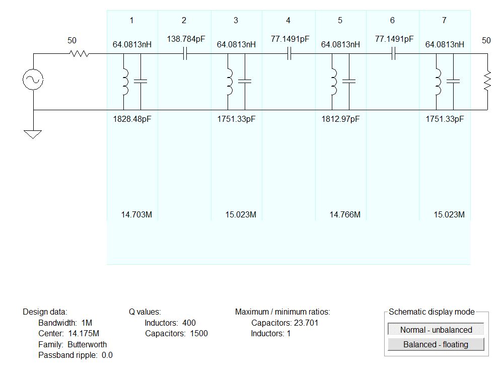
Here’s how I started with the Elsie program. Note that to get a 50 ohm match on both ends it needs an impractically low value for the coils (.064 uH).
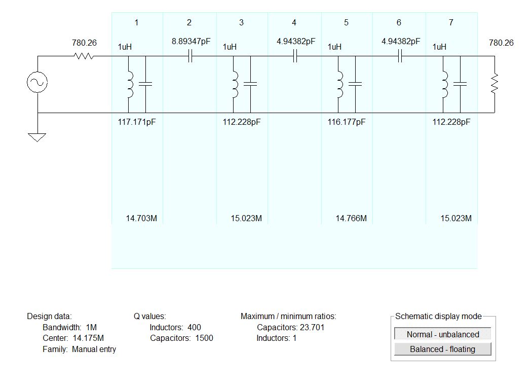
But Elsie lets you specify the coil value. So I then I went with 1 uH. But with this value you don’t get 50 ohms at either end. You need a matching network. Elsie provides this too!
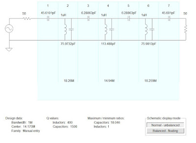
I asked Elsie to match my BP filter to 50 ohms. It provided several options to do this — I went with a simple capacitive impedance divider. But alas, I was now bumping up against the 7 limit of the free version of Elsie so I had to reduce the number of LC elements from 4 to 3. Bummer.
With 3 LC tuned circuits and matched to 50 ohms the plot looks OK. But I would have preferred 4 LC circuits.
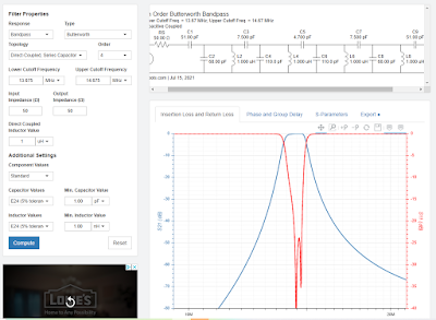
The rftools website created a BP filter for me with 4 LC elements, and matched to 50 ohms. Very useful. https://rf-tools.com/lc-filter/
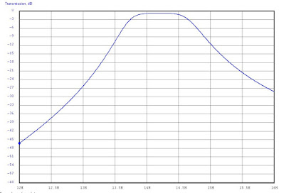
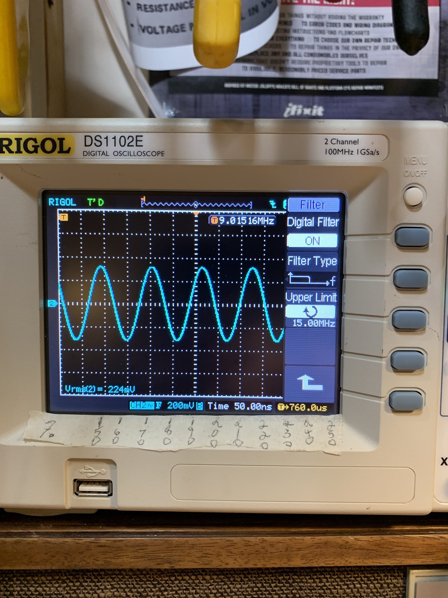
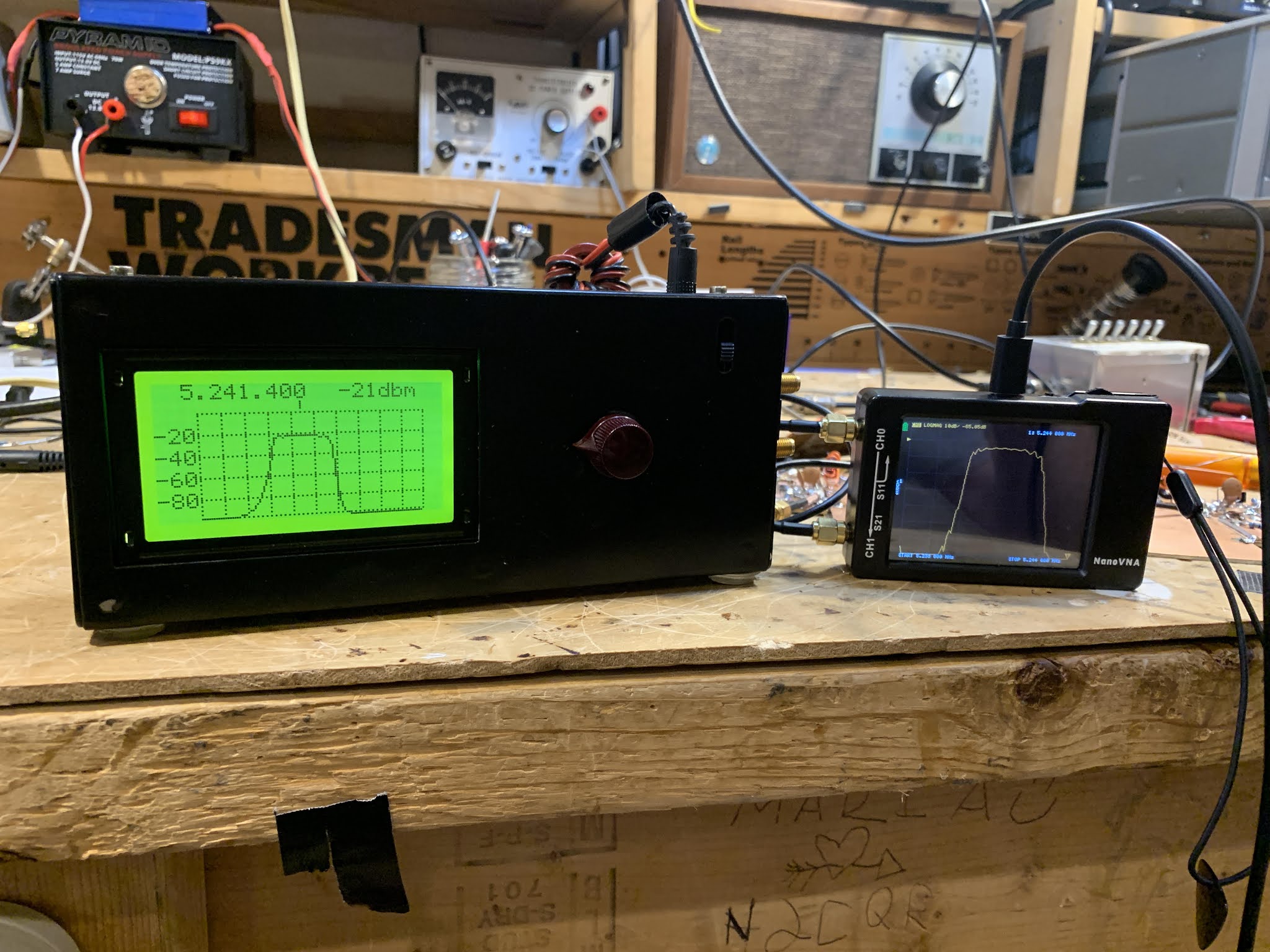
But here’s my problem: With both the filter designed by Elsie and the one designed by rftools, I found that the filter passband was too low. It was in the 12 – 13 MHz range. I found that by removing 3 turns from the 1 uH coils I could move the passband up to the desired range. But why the discrepancy? I was measuring the coils and the caps with an AADE meter. I was testing the passband both with a NanoVNA and with a combination of an HP8640B sig gen and a Rigol oscilloscope (with the filter terminated into a 50 ohm resistor). Any suggestions on why these filters should have passbands lower than predicted would be appreciated.
Mythbuster Video #4 — First Signals, 75 meter Bandpass Filter, Yaesu VFO output
This receiver required almost no coaxing or tweaking, probably because I had been so careful about testing and measuring each of the stages.
I have been pleasantly surprised at how well the receiver works without an RF amplifier ahead of the first mixer. But I need to know how much AF gain I have in order to understand how/why the entire receiver works so well. I think I have about 35 db of gain (combined) through the two TIAs and the crystal filter. That would mean that all of the remaining gain is provided by the AF amplifiers (with some loss in the product detector). I haven’t really measured the gain of the AF preamp/LM386 combo, and I had some trouble measuring the input impedance of the pre-amp with the NanoVNA.
The 75 meter LC filter to the left of the VFO is actually a bandpass filter, not the lowpass filter. And what I call “the mixer” to the right of the VFO is really the Product Detector/BFO.
For the 75 meter bandpass filter, I used the ELSIE program.
75 meter Bandpass Filter designed in Elsie. 10 turns on a T50-2 toroid yield .46uH.
Here’s the plot from Elsie on the 75 meter BP filter.
Alan W2AEW asked for a picture of the VFO output.
On this shot I had the probe between theVFO and the
outboard booster amp that I built to bring it to 7dbm.
Mythbuster Video #2 — 10 Pole Crystal Filter
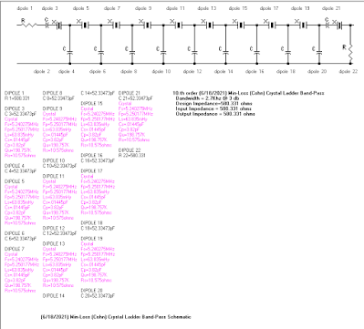
This is a 5.2 MHz crystal filter. I used the G3UUR method for determining the crystal’s motional parameters. I then used Dishal and AADE software to design a 10 pole Cohn Min-Loss filter. I tested the bandwidth with an Antuino Scalar Network analyzer (thanks Farhan!) and a NanoVNA. I found the passband to be a bit tight for SSB, so I replaced the capacitors with caps of a slightly lower value — this broadened the passband. It is still a bit tight, but the SSB audio — while not enhanced or Hi-Fi — sounds fine.
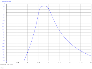
Passband filter shape as seen in the Antuino and in the NanoVNA. The -20 db line in the Antuino actually corresponds to no loss.
The schematic provided by the AADE software. Dishal software may have come up with better, more correct values for the capacitors.
The passband as predicted by AADE. Skirts so nearly vertical as to strike fear in the hearts of SDR owners!
Filter under construction — waiting for the caps from Mouser.
First scan with the NanoVNA. Insertion loss looks very high but that is only because I am terminating the filter with resistors — I just wanted to see the passband shape.
10 Pole Crystal Filter Passband as Seen in Antuino and NanoVNA

I continue to work on the “Mythbuster” rig, but I am taking it slow, trying to learn something from each stage. I’m especially trying to master the used of the great test gear that has arrived in my shack in recent years: The Antuino, the NanoVNA, and the TinySA.
Above you can see the passband of the 10 pole crystal filter as measured across the 50 ohm terminations on the filter. I use simple FT37-43 transformers to match the filter impedance down to 50 ohms. I used the Antuino first — it scanned the passband and held the image on its screen. I then disconnected the Antuino and connected the NanoVNA. So in this shot you can see the passband on both devices.
You will notice that the Antuino says there is a 20db insertion loss. That’s only because in the Antuino 20db is really 0 db loss. I think the NanoVNA gives a more accurate insertion loss reading — about 3-5 db. The cool thing is how similar the shapes of the passband are.
SolderSmoke Podcast #231 — Travel, SST, Mythbusting, Filters, TIAS, NanoVNAs, DC RX in SPRAT, Drake A Line, Spillsbury, STICKERS! Mailbag
SolderSmoke # 231 is available:
Annual Field Day Special Edition
Travelogue: To the Dominican Republic!
New dog — Meet Guapo (see below).
A great Father’s Day for Pete and Bill. I got a TinySA.
Pete got some cool chick magnet glasses (see below).
Watch out Newbury Park!
Bill’s Activity
SST Transceiver. Took it to Dominican Republic.
Made only one contact, but QRP-QRP.
Not a lot of CW activity, and not a lot around 14.060.
A lot more FT8 visible on the NA5B WebSDR.
That might be better for this kind of operation.
I might try SST CW out today from the backyard. Field Day!
Fired up my 20 meter DSB NE602 rigs. Made two contacts.
Still trying to fully understand the NE602 Gilbert Cell. Lots of mystery in there.
Building “The MythBuster.” 75/20 with sideband inversion.
10 pole 5.2 MHz filter. Used Dishal and AADE.
Used NanoVNA to see the passband.
G3UUR for crystal parameters.
Cohn Constant K topology.
Also used NanoVNA to check input and output impedance on the TIA amps I will use around the filter.
Pete’s activity:
Article on DC receiver in SPRAT. FB response. 50 receivers under construction.
Work on Drake A Line.
Jim Spillsbury.
——————————
The N5JHH IBEW SolderSmoke stickers (see above and below). How we will use them.
Mailbag:
N2SVD
K8ITY
Tom (Junkbox receiver)
N0ZIB (Curse you, SolderSmoke!)
DL6ID
N2NLY
VK2EMU
ZS1KE
AF7O
NG2E
VU2ESE
OK1RP
N5JHH
Hodgepodge: Moving the Carrier Oscillator Frequency (and a Flashback to 2002) (Video)
As explained in the video, in the course of using my RTL-SDR dongle I noticed that the signal being put out by my Hodgepodge rig had some problems. There was poor opposite sideband rejection, and in terms of audio quality I has putting out too many lows and too few highs. I figured the problem was the result of the carrier oscillator frequency being a bit too low, a bit too close to the flat portion of the crystal filter passband. I needed to move that carrier oscillator frequency up a bit.
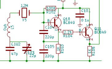
BITX40 Module BFO
In the actual BITX40 Modules, L5 was replaced by just a jumper wire, and the C103 trimmer was not on the board. Farhan and his team instead selected X5 crystals to match the passband of the 12 MHz crystal filter. Mine was originally at 11.998653 MHz. But I wanted to tweak mine a bit — I wanted to move it up about 500 Hz. Reducing the capacitance would move the frequency up. Putting capacitance in series with C102 would have the effect of reducing the capacitance in the circuit. I just removed the jumper wire and used the holes for L5. First I put in a single 30pf capacitor. This dropped the capacitance between X5 and ground to 18 pf. That resulted in too large a shift. So I added another 30 pf cap in parallel with the first one. This resulted in a total capacitance from X5 to ground of 26 pf. This was about right — the carrier oscillator/BFO frequency was now 11.9991 Mhz. I had moved the carrier oscillator frequency up by 447 Hz — just about what I was hoping for.
This was a very satisfying fix. it was a chance to put to use experience with other SSB rigs, to make use of the RTL-SDR dongle as a diagnostic tool, and to tinker with the BITX40 Module in the way that Farhan had intended for it to be tinkered with.
I’d done this kind of adjustment before, but without the benefit of an SDR display. Below is the story of one such adjustment.
———————————
A Flashback to 2001-2002
(From my book “SolderSmoke — Global Adventures in Wireless Electronics”)
Now it was time for some debugging and fine tuning. I needed to make sure that the frequency of the carrier oscillator was in the right spot relative to the passband of the crystal filter. If it was set too high, the filter would be chopping off high notes in my voice that were needed for communications clarity, and it would allow too much of what remained of the carrier (residuals from the balance modulator) through. If it was set too low, the voice signal transmitted would be lacking needed base notes. I didn’t have the test gear needed to perform this adjustment properly, but my friend Rolf, SM4FQW, up in
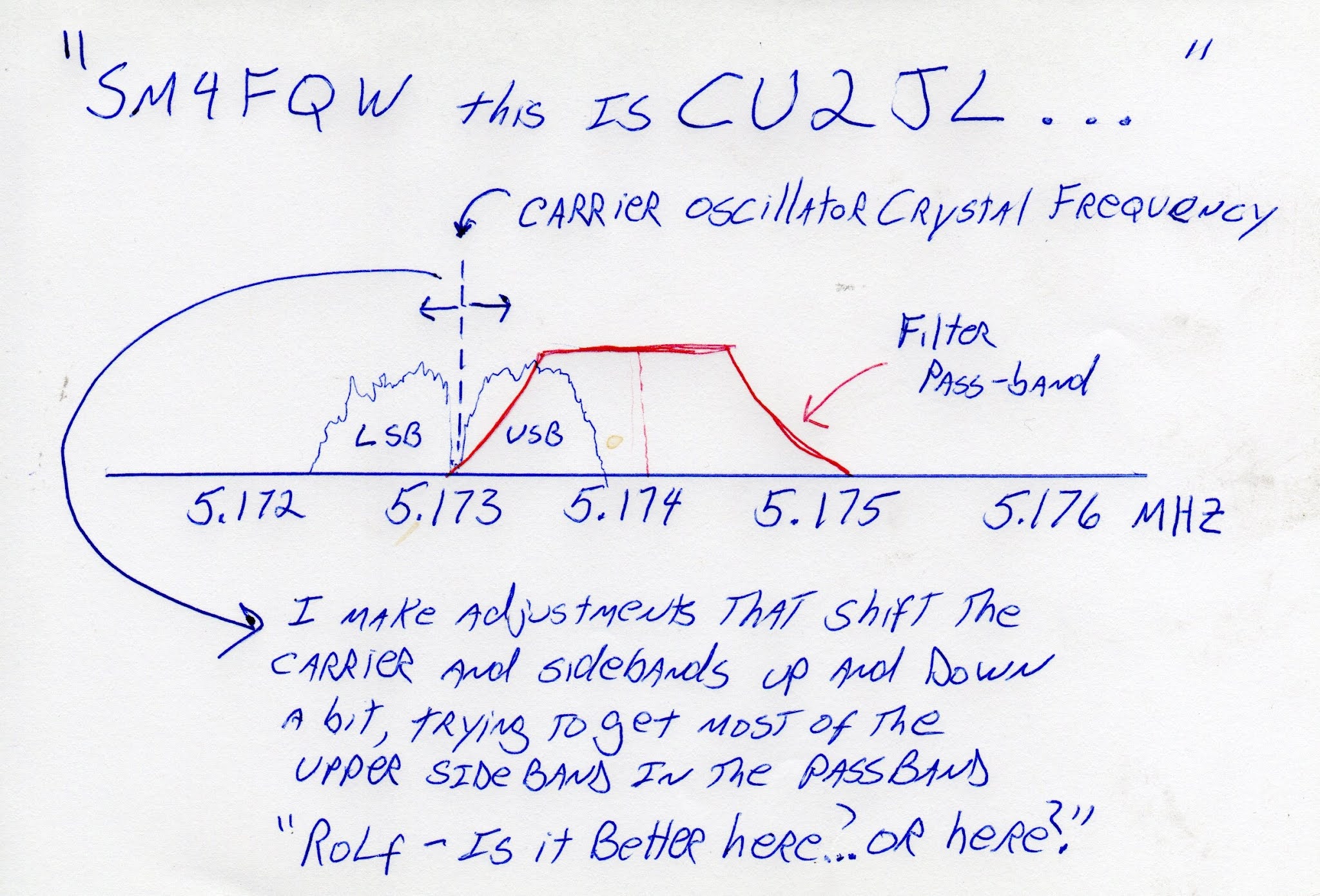
One night, during a conversation with Rolf, I explained my problem and he offered to help me make the adjustments… by ear. Performing an electronic version of open-heart surgery, with power on and Rolf on frequency, I opened the case of the new transmitter. The carrier oscillator has a small capacitor that allows the frequency of the crystal to be moved slightly. With Rolf listening carefully, I would take my screwdriver and give that little capacitor a quarter turn to the right. “Better or worse?” I would ask.
I think this little adjustment session captures much of the allure of ham radio. There I was, out in the
Guilt Trip: Video on the Heath QF-1 Q Multiplier
Hack-A-Day had a nice post about this piece of gear:
My radio emotions were swinging wildly as I watched this video.
Readers may recall that over the years I have brutally cannibalized several QF-1s. I was enticed into doing this precisely by the tuning cap that the videographer so alluringly describes. It has a built in 7:1 reduction drive! How could I resist? These wonderful caps live on in several of my homebrew rigs.
I also put the conveniently sized metal cabinets to good use — one holds frequency counters for my AM station, the other houses an Si5351 VFO/BFO that can be used with many rigs.
After extracting the cap and putting the boxes to good use, I was left with the remainder of the circuitry. I recently put even this stuff to use by using the coils to make a triple LC circuit filter for 455 kHz. This may someday be used in a receiver. So you see, I’ve not been wasteful.
And the thing only cost 9 bucks back in the day… So I didn’t really do anything bad. And besides, adding a regen circuit to a superhet is kind of backwards, right?
But then the video producer started talking about how nice his QF-1 looks, even after more than 60 years. And about how much it improved the performance of his AR-1. And then, the kicker: He said the QF-1s are now “relatively rare.”
I hang my head in shame. I am a serial QF-1 killer. And I don’t know if I can stop.
SolderSmoke Podcast #227: Solar System, SDR, Simple SSB, HA-600A, BITX17, Nesting Moxons? Mailbag

SolderSmoke Podcast #227 is available:
Travelogue
Mars is moving away. Jupiter and Saturn close in the sky. And the Sun is back in action – Cycle 25 is underway. Also, the earliest sunset is behind us. Brighter days are ahead.
Book Review: “Conquering the Electron” With a quote from Nikola Tesla.
No real travel for us: Hunkered down. Lots of COVID cases around us. Friends, relatives, neighbors. Be careful. You don’t want to be make it through 10 months of pandemic only to get sick at the very end. SITS: Stay In The Shack.
Pete’s Bench and Tech Adventures:
Backpack SDR keithsdr@groups.io
Hermes Lite 2
Coaching SSB builders
G-QRP talk
A new source for 9 MHz crystal filters
Bill’s Bench:
Fixing the HA-600A Product Detector. Sherwood article advice. Diode Ring wins the day. Fixing a scratchy variable capacitor. Studying simple two diode singly balanced detectors. Polyakov. Getting San Jian frequency counter for it.
Fixing up the 17 meter BITX. Expanding the VXO coverage. Using it with NA5B’s KiwiSDR.
Resurrecting the 17 meter Moxon. But WHY can’t I nest the 17 meter Moxon inside a 20 meter Moxon? They do it with Hex beams. Why so hard with Moxons? DK7ZB has a design, but I’ve often heard that this combo is problematic. Any thoughts? I could just buy a 20/17 Hex-beam but this seems kind of heretical for a HB station.
Suddenly getting RFI on 40 meters. Every 50-60 Hz. Please tell me what you think this is (I played a recording).
MAILBAG:
Dean KK4DAS’s Furlough 40/20
Adam N0ZIB HB DC TCVR
Tony G4WIF G-QRP Vids. Video of George Dobbs.
Grayson KJ7UM Collecting Radioactive OA2s. Why?
Pete found W6BLZ Articles
Rogier KJ6ETL PA1ZZ lost his dog. And we lost ours.
Steve Silverman KB3SII — a nice old variable capacitor from Chelsea Radio Company.
Dave K8WPE thinks we already have a cult following.
Dan W4ERF paralleling amps to improve SNR.
Jim W8NSA — An old friend.
Pete Eaton WB9FLW The Arecibo collapse
John WB4GTW old friend… friend of:
Taylor N4TD HB2HB
And finally, we got lots of mail about our editorial. No surprise: Half supportive, half opposed. Obviously everyone is entitled to their opinion. And we are free to express ours. It’s a free country, and we want it to stay that way. That is why we spoke out.
Yesterday the Electoral College voted, finalizing the results. All Americans should be proud that the U.S. was able to carry out a free and fair national election with record turn out under difficult circumstances. And all loyal Americans should accept the results. That’s just the way it works in a democracy.
We are glad we said what we said. It would have been easier and more pleasant to just bury our heads in the sand and say nothing. But this was a critically important election and we felt obligated as Americans to speak out. We’d do it again. And in fact we reserve the right to speak out again if a similarly important issue arises.
Adam N0ZIB’s Direct Conversion Transceiver
This is obviously very cool, but looking ahead I think Adam should think about adding one more mixer, changing the bias on the TX amps, and adding a mic amp. Boom: A Double Sideband Transceiver.
Pete wrote: When I was in the US Navy and a particular unit did something outstanding – the Command ship would raise the Bravo Zulu Flag for a job well. Don’t know if you can see it there in MO but I have raised the BZ flag to you. Outstanding and congratulations.
Bill and Pete:
Just finished a DC transceiver using Arduino nano, SI5351 (my sincerest apologies, Bill), diode ring mixer and lm386 audio amp. The transmit portion is a two-stage class AB pre-amp (from EMRFD page 2.32), which is driving an IRF510 final (biased at 2.08 volts) from Pete’s design. Output is about 5watts into a CWAZ low pass filter, based on the design from here: https://www.arrl.org/files/file/Technology/tis/info/pdf/9902044.pdf
I’m using a manual TX/RX switch which is doing multiple things. It brings the Nano A1 LOW, offsetting the transmit frequency 600 Hz for CW, grounds the audio input to prevent deafness (learned that one the hard way), and it engages a relay that switches the antenna from the receiver to the transmit, and also turns on the transmitter stages. Keying is through the first stage of the pre-amp.
I still have some tidying up to do, and I’m not sure the LPF works so well using two component inductors instead of all toroids, but I finished it today and made my first QSO into Ontario almost 1000 miles away. It’s been great fun!
73,
Adam
N0ZIB
Missouri
Wrapping up the HA-600A Product Detector Project — Let’s Call Them “Crossed Diode Mixers” NOT “Diode Rings”
This has been a lot of fun and very educational. The problem I discovered in the Lafayette HA-600A product detector caused me to take a new look at how diode detectors really work. It also spurred me to make more use of LTSpice.
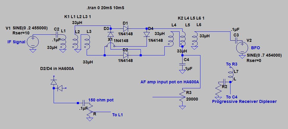
In the end, I went with a diode ring mixer. Part of this decision was just my amazement at how four diodes and a couple of transformers can manage to multiply an incoming signal by 1 and -1, and how this multiplication allows us to pull audio out of the mess.
But another part of the decision was port isolation: the diode ring mixer with four diodes and two transformers does keep the BFO signal from making its way back to into the IF chain. This helps prevent the BFO signal from activating the AGC circuitry, and from messing up the S-meter readings. LTSpice helped me confirm that this improvement was happening: in LTSpice I could look at how much BFO energy was making its way back to the IF input port on the diode ring mixer. LTSpice predicted very little, and this was confirmed in the real world circuit. (I will do another post on port isolation in simpler, singly balanced diode mixers.)
At first I did have to overcome some problems with the diode ring circuit. Mine seemed to perform poorly with strong signals: I’d hear some of the “simultaneous envelope and product detection” that started me down this path. I also noticed that with the diode ring, in the AM mode the receiver seemed to be less sensitive — it was as if the product detector circuit was loading down the AM detector.
One of the commenters — Christian — suggested putting some resistance into the input of the diode ring circuit. I put a 150 ohm pot across the input, after the blocking capacitor. The top of the pot goes to the capacitor, the bottom to ground and the wiper to the input of L1 in the diode ring circuit (you can see the circuit in the diagram above). With this pot I could set the input level such that even the strongest input signals did not cause the envelope detection that I’d heard earlier. Watching these input signals on the ‘scope, I think these problems arose when the IF signals rose above .7 volts and started turning on the diodes. Only the BFO signal should have been doing that. The pot eliminated this problem. The pot also seemed to solve the problem of the loading down of the AM detector.
With the pot, signals sounded much better, but I thought there was still room for improvement. I thought I could hear a bit of RF in the audio output. Perhaps some of the 455 kHz signal was making it into the AF amplifiers. I looked at the circuit that Wes Hayward had used after the SBL-1 that he used as product detector in his Progressive Receiver. It was very simple: a .01 uF cap and 50 ohm resistor to ground followed by an RF choke. I can’t be sure, but this seemed to help, and the SSB now sounds great.
A BETTER NAME?
One suggestion: We should stop calling the diode ring a diode ring. I think “crossed diode mixer” or something like that is more descriptive. This circuit works not because the diodes are in a ring, but because two of them are “crossed.” From now on I intend to BUILD this circuit with this crossed parts placement — this makes it easier to see how the circuit works, how it manages to multiply by -1, and to avoid putting any of the diodes in backwards.
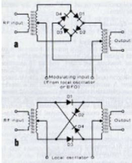
I prefer the bottom diagram
A KNOWN PROBLEM?
I’m left wondering if the engineers who designed the HA-600A were aware of the shortcomings of the product detector. It is really strange that my receivers lacks a 12V line from the function switch to the product detector. And it is weirder still that the detector works (poorly) even with no power to the transistor. What happened there?
When you look at the HA-600A manual, you can see a hint that maybe they knew there was a problem. For CW and SSB, the manual recommends leaving the AF control at the quarter or halfway point, then controlling loudness with the RF gain control. This would have the effect of throttling back the RF gain (and the potential for product detector overload) when strong signals appear. MGC in addition to the AGC. Any memories or insights on this would be appreciated.
HA-600A Gets a New Coat of Paint — After Almost 50 years!
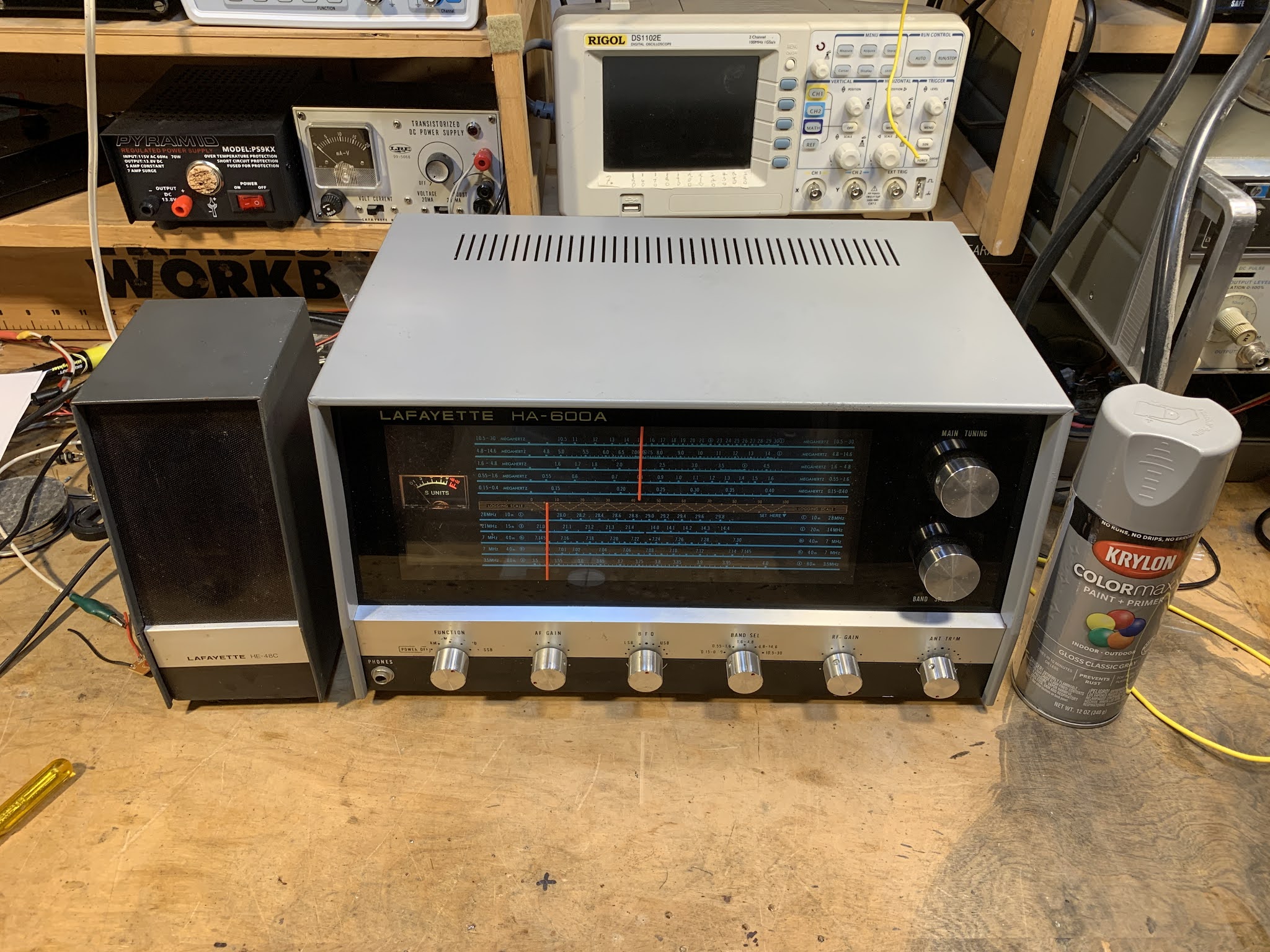
The HA-600A that I picked up last week was looking kind of sorry. There was a lot of rust on the cabinet. Below is the before picture.
I’m not really into cabinetry or radio aesthetics, but it is amazing what a 6 dollar can of spray paint can do. Formula 409 also helps. I moved the light bulbs forward a bit to get more light on that Juliano Blue dial.
I am really enjoying this radio. It has brought back many memories. I think I got one for Christmas in 1972. I was 14. I got my Novice ticket on April 27, 1973 and made my first contact on July 19, 1973. For that first contact I was using an HA-600A and a Heathkit DX-40. Later I used the Lafayette with a Heathkit DX-100. The HA-600A was replaced by the far superior Drake 2B on April 11, 1974. So I used this receiver for more than two years.
Looking around inside this receiver (and following up with Google) I learned some more about it:
— It was made in Japan.
— The manual says it has a “mechanical filter” but in fact it has a Toyo ceramic filter. This may have been just an honest mistake by the folks who wrote the manual — maybe they didn’t understand the difference between the two types of filters.
— There is a big difference between the HA-600 and the HA-600A, mostly in the front end circuitry. The HA-600 has fewer amplifier circuits at the front end. This probably explains why the HA-600 I picked up did not seem to live up to my memories of my teen-year HA-600A.
The fellow who gave it to me tells me that it had belonged to the short-wave listener father of a friend of his.
I know we have a lot of tube-type receivers that are much older than this thing, but I still think it is pretty amazing that this is a receiver that I used almost half a century ago. And it is still as good as new.
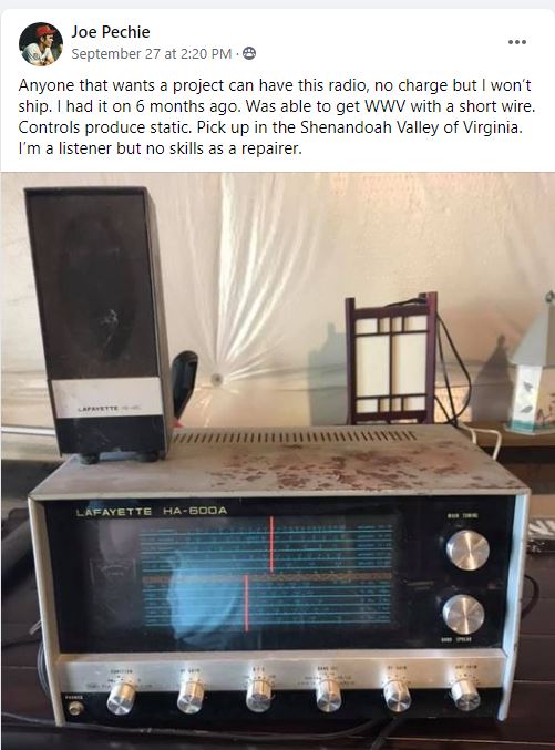
TRGHS — My First SW Receiver Offered FREE for Pickup — The Lafayette HA-600A (Looking for Globe VFO Deluxe)
So on September 27,2020, I was sitting quietly in my shack, perusing the postings on various radio-related Facebook groups, when suddenly I saw it: my very first shortwave receiver, the magic box that had put me firmly on the path to amateur radio, the Lafayette HA-600A. Joe, the owner, was offering it FREE to anyone willing to pick it up at his home in Virginia’s Shenandoah Valley. Holy Cow! I was scheduled to drive through that very valley later that week. A message was sent and the deal was done. CLEARLY THE RADIO GODS HAD SPOKEN (TRGHS).
Sure, the cabinet looked a bit rough, but I had high hopes for this receiver. A while back I had — in a similar fit of nostalgia — bought what had been advertised as a Lafayette HA-600A on e-bay. But it turned out to be a Lafayette HA-600 (no A). I immediately noticed a big difference in performance. That was NOT the radio that I remembered, not the receiver that had carried HCJB and Radio Moscow to me. Joe was clearly offering the A model.
A few days later I was in Joe’s front yard for the hand-off, and a few days after that the HA-600A was on my bench.
I quickly realized how little I knew about this receiver. Mine was a Christmas gift, probably in 1973. (A few days ago I talked to my mom and thanked her for driving all the way to New Jersey to get this receiver for me.) I was so taken with this thing that I feared doing something — anything — that might mess it up. I lived in fear, for example, that some sort of freak mid-winter lightning bolt might destroy it. I covered it with a towel each night lest dust encumber its “jeweled movements.” Obviously I was just not inclined to crack open the case and have a look around. So I didn’t, and the receiver remained pretty much an appliance for all the time I owned it. (I eventually sold it on consignment at Electronics 59 in Spring Valley, New York. The proceeds probably went toward the purchase of a much better Drake 2-B receiver.)
I downloaded the manual and familiarized myself with the receiver: It is a single conversion superhet with a 455 kc IF. It is all solid state with no ICs — all discrete transistors and diodes. The manual claims it has a mechanical filter. I kind of hoped for something like a Kokusai mechanical filter, but it turns out that the filter was really ceramic, not mechanical. Bummer.
The thing fired up right away and was inhaling on the correct frequencies. I noticed immediately that (as Joe had indicated) some of the controls were scratchy. I also noticed that the ganged band selection switch was intermittent and required some jiggling to get it to work properly. A few squirts of Deoxit D5 took care of all that. There seemed to be a bit of dirt in the main tuning capacitor, but I think I managed to blow that out using a can of Dust-off. I was quickly listening to the SW broadcast stations, and to radio amateurs on 75 and 40 meters.
Out of curiosity, I compared schematics of the HA-600 and the HA-600A. There was indeed a big difference — the front end of the 600 lacks a lot of the RFA amplification circuitry of the A model. That’s probably why is seemed so deaf and so different from what I remembered of the A model.
There is really not a lot to do on this receiver. I’ll get some paint to fix up the top cover. I may check the alignment. But this single conversion receiver is so simple that alignment would be quite easy. In many ways this receiver seems like a solid state analog to the Hammarlund HQ-100, but without the clock, and without the regeneration circuitry. The dial lacks the exotic station locations (Java!) that make many of the older receivers so much fun. I guess this is an indication that this receiver was aimed more at amateur radio operators than at shortwave listeners ( I was both). I wonder how the ham band-only HA-800 compares to the HA-600A?
I could pair this receiver up with a DX-40 transmitter that I have on the shelf and I’d be most of the way toward re-creating my novice station. Anyone have a Globe VFO Deluxe? That would complete the setup.
Thanks very much to shortwave listener Joe Pechie for providing what is, for me, a very meaningful piece of gear.
Here’s a short video on the receiver:
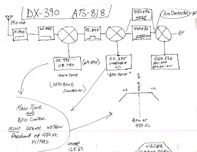
Video on the Strange Tuning of the Radio Shack DX-390 Receiver

I’m more of a single conversion guy myself, but in working with the DX-390 I came to appreciate the benefits (especially regarding image rejection) of the double conversion technique.
While working on the DX-390, I discovered that the BFO control on the front panel DOES NOT change the BFO frequency. It was fun to try to figure out why the designers did it this way. It does make sense once you consider the limitation imposed by that PLL main tuning oscillator that only moves in 1 kHz steps. I hope the video explains things.
Here is the drawing I used in the video:
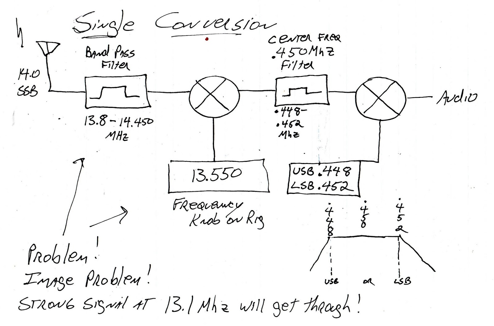
And here is a drawing that shows how a single conversion superhet with a fixed or switchable (usually crystal-controlled) BFO works:
Earlier this month I did a blog post on my repair of a broken DX-390: