 |
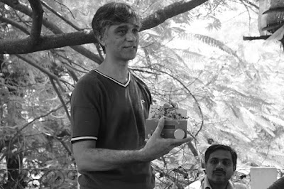
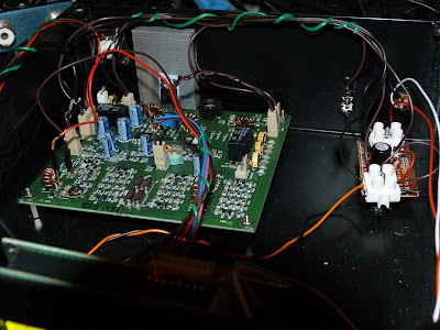
| Bore and Heriberto’s uBITX board |
Nowhere is the International Brotherhood of Electronic Wizards more evident than in the work on the rigs designed by Farhan. With the BITXs we see rigs designed in India that are now being built and modified all over the planet. Here are just a few examples of the global collaboration currently underway:
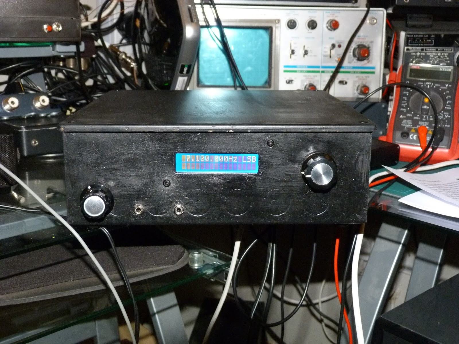
In Italy, Giuseppe is putting a BTX40 on 20 meters and making it a dual bander:
Hi everyone, I just completed some tests on a Bitx40 running in 20 meters band. I addes the 20 as secondary band activate when needed. I apply some mods to switch to secondary QRPLab BPF filter centered to 20 meters and removed the C91 and C92 caps to work in USB. I done some RX tests in the weekend of iaru hf contest to listen some stations Active.
Here the issues registered:
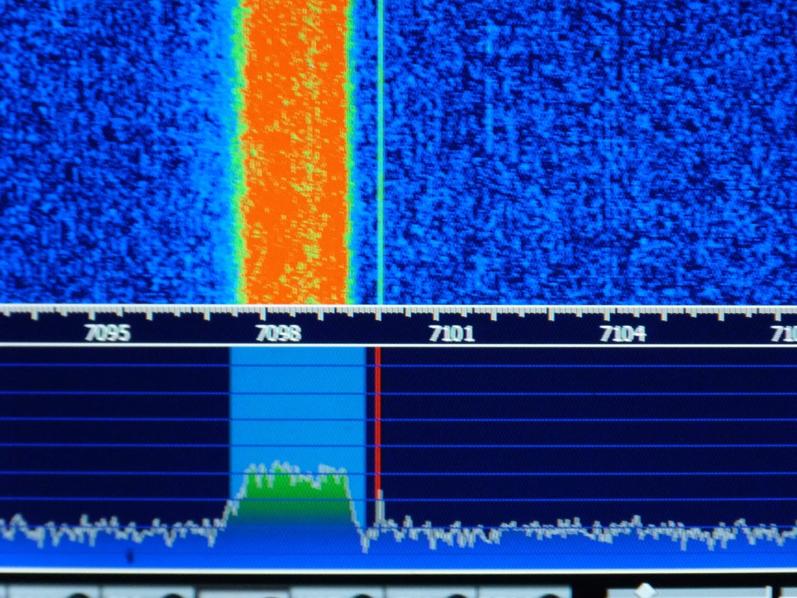
1) the 20 RX sensitivity was a bit weak compared to 40 meters. I need to increase volume. ( To receive the 20 meters the vfo run to 26 MHZ, mybe some stage suffers of poor performance in this High frequency?)
I also tryed to increase the vfo over maximum allowed by raduino, using external buffer, but no results.
Please read the issues as: work but could work better!
2) the RX was not very clean: voice acceptable, but RX of Digital mode not very stable ( probably the cause could be the vfo shift for poor tuning control. I need to add lock function in firmware …) Or interferences for free wire of connection.
3) Sometimes when switch on or change vfo to other band or mode, the bf amplifier start a self oscillation …Resulting in my wife’s screaming (the tests were also performed during the night!)
No tests was performed at the moment in TX because i need to install the LPF for the new band.
The firmware to make the test was a modified version of 1.17.1, few temporary mods to preset the vfo b to 14 MHz USB and correct the freq. Display.
These my tests.
Giuseppe Callipo IK8YFW.
Pavel is a young fellow in Cuba who is doing great things with the Raduino software:

Hi to all.
The code was updated, the change log is this:
v1.4Update to catch up with the features added in the Raduino v1.17.1 from Allard’s code (CW SPOT and bug fixes)
- Upgraded the operations instructions
- More user friendly version with embedded images.
- Add instructions for the S-meter, AGC and TX-power mods details and tricks.
- Moved all images to its own folder “images”.
As usual tips/bugs/comments/suggestions are welcomed, you can reach the code here: https://github.com/pavelmc/bitx40/
There is a inoffensive bug in the calibrate process, in which the actual calibrate value is not correctly showed in the LCD until you move the pot to adjust it, I’m working on it.
I’m slowly working in this direction now:
- Bug removal in the calibrate function.
- Finish the upgrade of the Si5351mcu lib with some improvements.
- Adding CAT support via ft857d lib (https://github.com/pavelmc/ft857d):
- Full compliance needs get rid of all the blocking delay() sentences and that need a structural/paradigm code change and a lot of testing (I have Fldigi/MixW/Hamlib to test, I think if that 3 works the rest will do it)
- Moving to a library (yatuli: https://github.com/pavelmc/yatuli) for the pot usage, that will ease the process of implementing the CAT as almost all delay() calls are related to pot/clicks, so I’m on it.
- Maybe implement a multiclick lib to optimize the code and make it more easy to understand.
Any thoughts or whishes related to that?
I plan to make the CAT operation optional via a #define declaration as not all of us will/want-to use that.
73 Pavel CO7WT
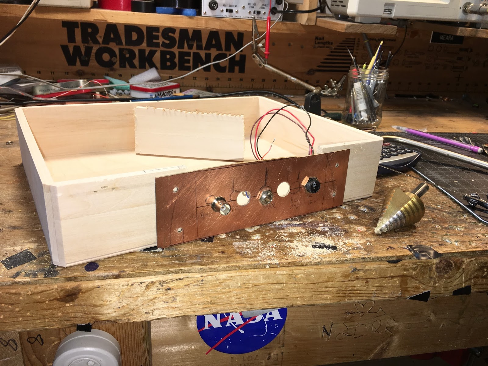
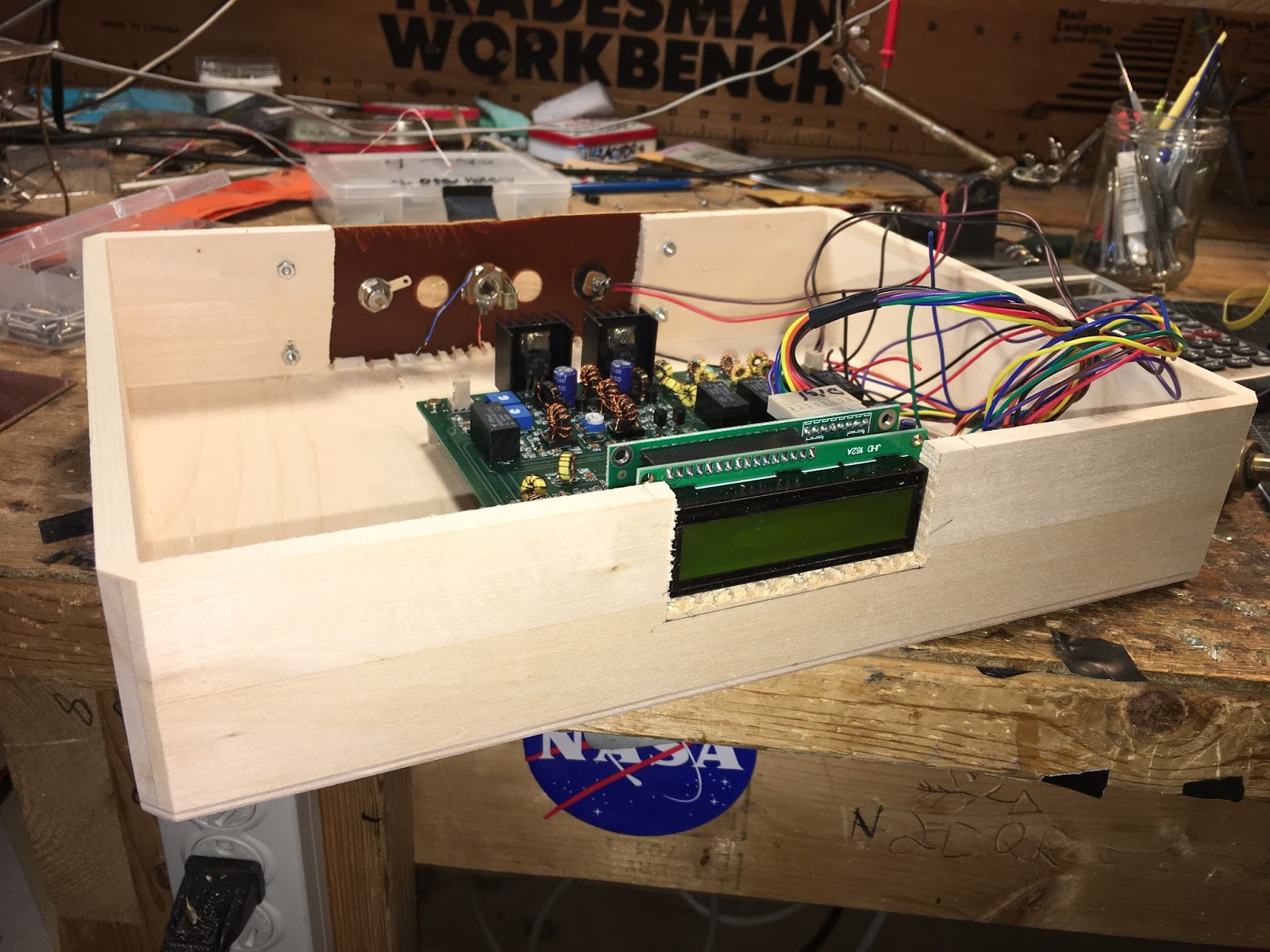
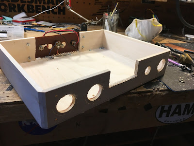
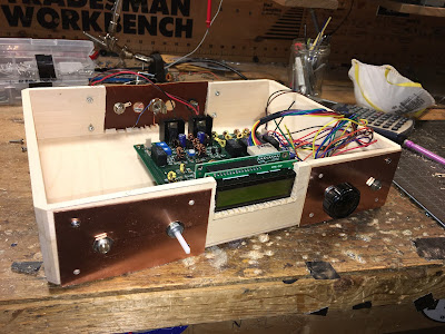
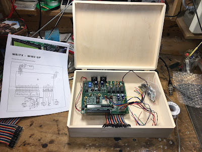
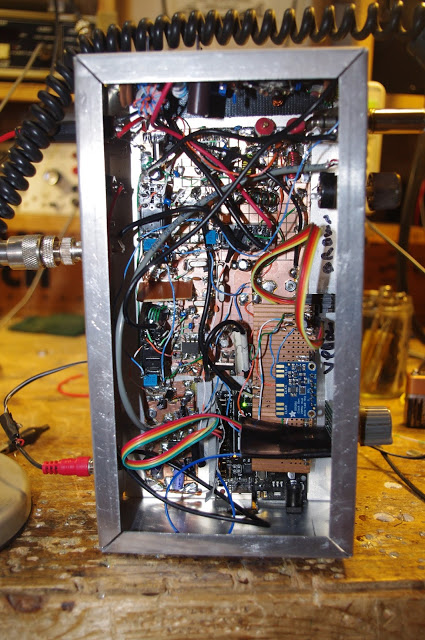
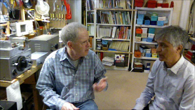
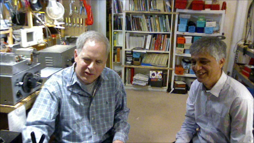
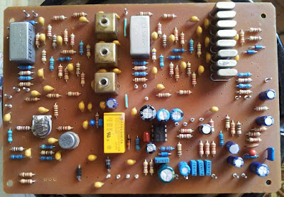
Here we see Bore in Montenegro working on a uBITX designed in Cuba by OM Heriberto
Hi Colleagues
Bore Lezaic from Montenegro is working on the uBitx PCB designed by Heriberto -CM2KMK- from Havana, Cuba
Here some pictures he(Bore Lezaic) have posted in my FB wall.
Any question regarding uBitx PCB please send to Heriberto Gonzalez Mendoza at cl2kmk@frcuba.cu (please take care with the email address it is slight different to his actual call sign). Qrv’s 73’s Jc
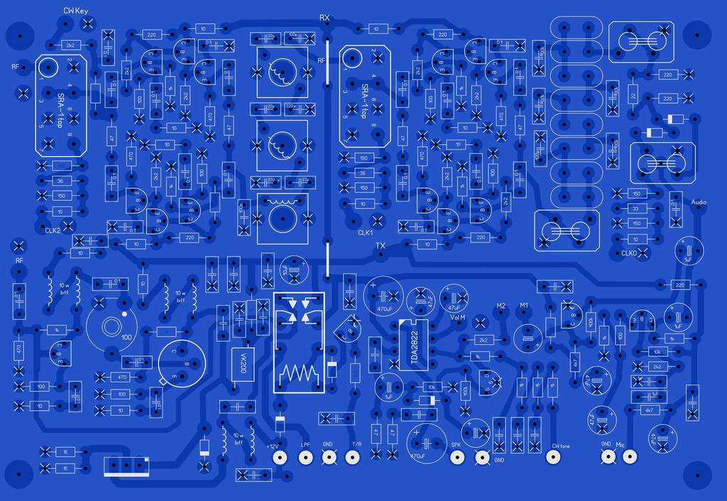 |
| Bore and Heriberto’s Board |
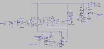
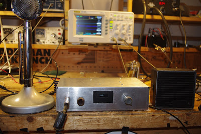
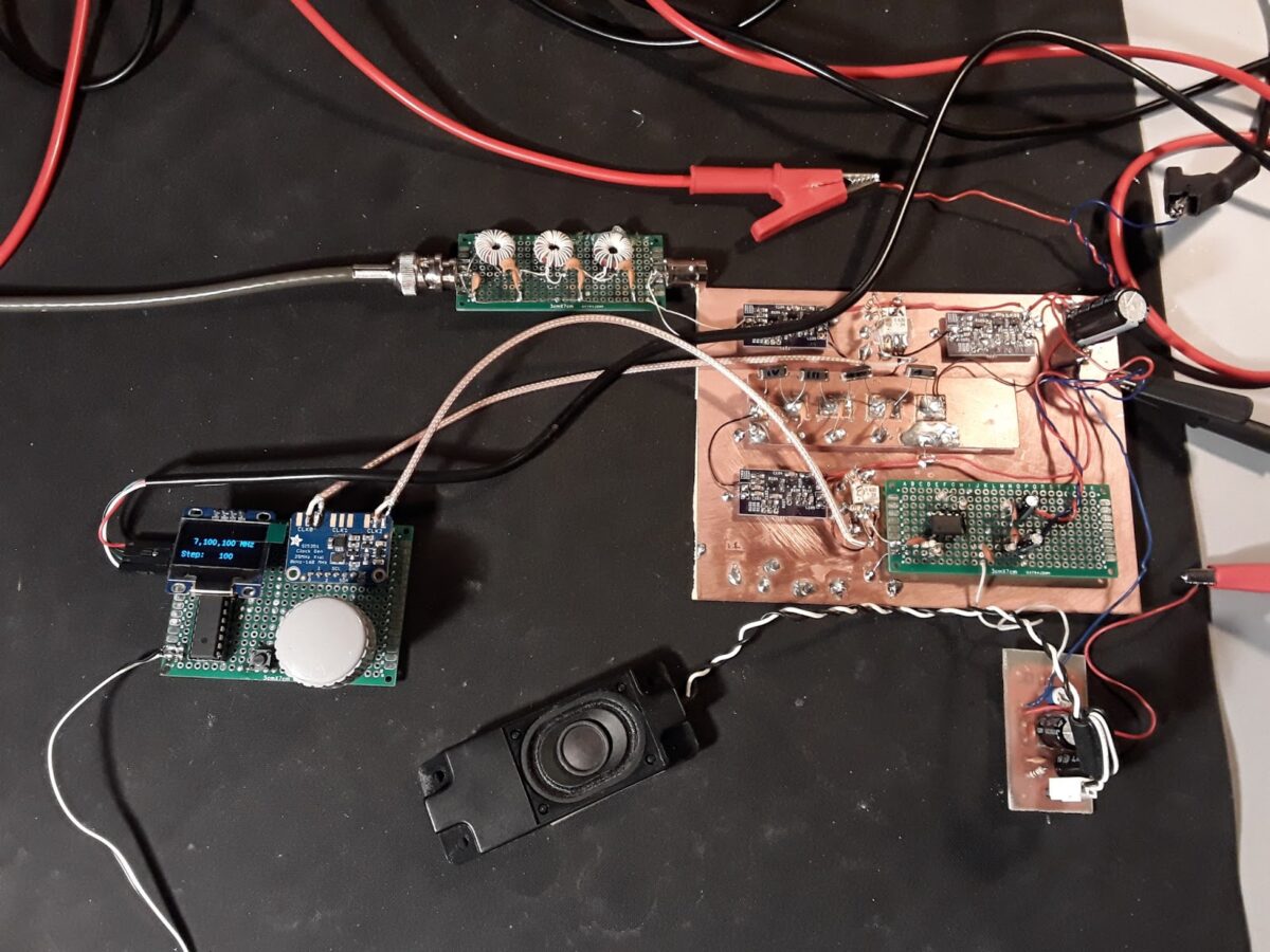
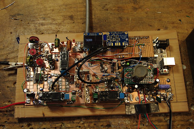
Hidehiko in Japan was struggling with some LCD noise in his experimental BITX40. I passed along the active filter circuit that I’d first seen in Roy Lewallen’s Optimized QRP rig.
To
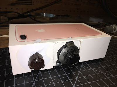
BITX20@groups.io Jul 29 2017 at 4:22 AM I’ve finished the Bitx40 experimental project today. I added the AF-AGC and LM386 POP limitter with raduino v1.20.1 (Thanks Allard). And I also added the DuinoVOX for Digital Mode operation. It’s a great radio but the problem is only the “LCD noise” when increasing the AF volume. hi… Can I reduce this noise? Or I have to use the analog VFO? Any suggestions welcome. ja9mat Hidehiko
To Hidehiko JA9MAT:
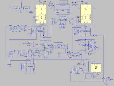
Very simple. Just three parts. NPN transistor (like a 2N3904) and a 47k resistor (collector to base) 100 uF cap (base to ground). Vcc the collector. Emitter goes to the DC power input of the AF amplifier. You can see my use of this circuit in the schematic in this blog post:
Look in the lower right, near the LM386 AF amplifier. Click on the schematic to enlarge. 73 Bill N2CQR
Thanks Bill,
Well I added “3-parts”(2N3904+47kohm+100uF) between the D18(1N4148) and the junction of R111(100ohm) and R1113(220ohm). The noise has absolutely gone!
ja9mat Hidehiko.
_._,_._,_