
Dean KK4DAS asked me to speak to our local radio club, the Vienna Wireless Society. It was a lot of fun. I talked about my evolution as a homebrewer, some of the rigs I made, the moments of joy, and the tales of woe. You can watch the presentation in the video above.
I was really glad to be able to explain in the presentation the importance of people like Pete, Dex, Farhan, Wes, Shep and even Dilbert.
I was also pleased to get into the presentation the N2CQR sign that Peter VK2EMU made for me. Thanks Peter!
Here is the URL to the YouTube video (also above):
https://www.youtube.com/watch?time_continue=3414&v=VHSr-v4QO7Q&feature=emb_logo
And here are the PowerPoint slides I used:
https://viennawireless.net/wp/wp-content/uploads/2020/06/VWS-presentation-Rig-here-is-homebrew.pdf
Category: Farhan
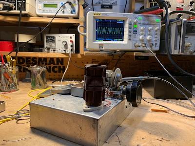
Video on Galaxy V VFO IN USE with BITX40 Module — 40 meter Bandsweep
Check out that fancy frequency readout. No glowing numerals here. But it does the job.
QSO Today — Episode 300 — Panel Discussion
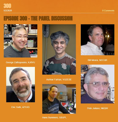
Congratulations to Eric Guth, 4Z1UG for reaching episode #300 on his QSO Today podcast. To commemorate the event, Eric organized a panel discussion. It was a real pleasure and honor to participate.
Listen to it here: https://www.qsotoday.com/podcasts/300
Thanks again Eric!
Videos on the Q-31 Quarantine AM SW Receiver Project (and some pictures)
I’ve been making some short, stage-by-stage videos of my Q-31 receiver project. So far I have seven videos. They are here:
https://www.youtube.com/user/M0HBR/videos
Please subscribe to my YouTube Channel. And give me some “thumbs up” if you like the videos.
Thanks. SITS! FlattenTheCurve! 73
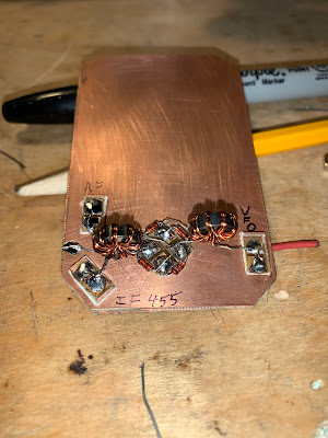 |
| Pads from Pete, toroids from Farhan |
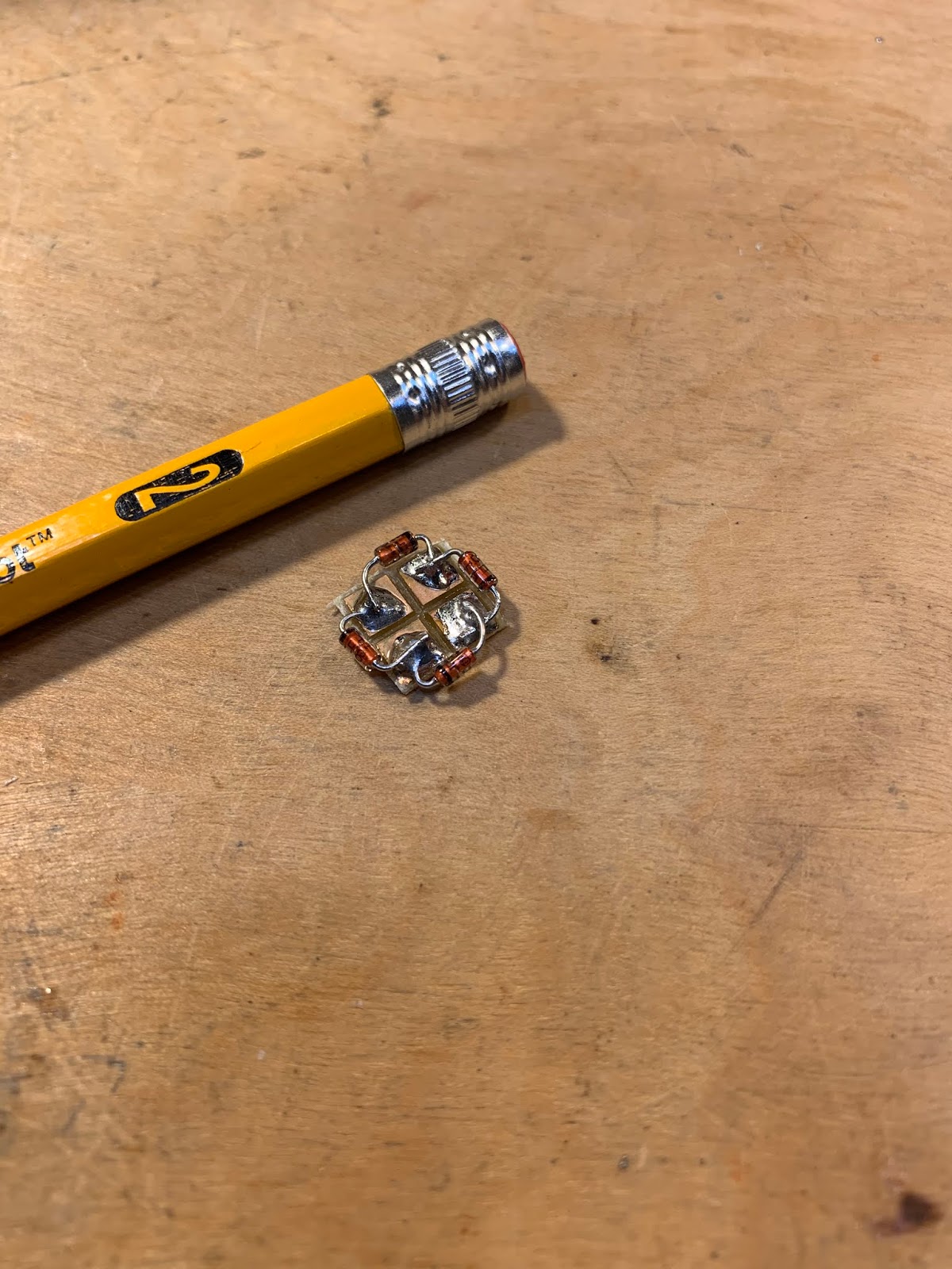 |
| The diode ring |
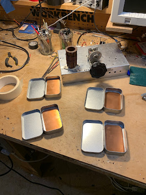 |
| Altoids-sized tins will hold the circuit boards |
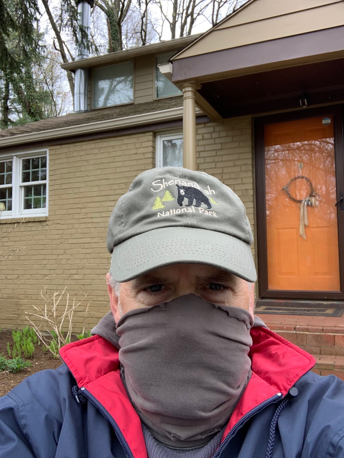 |
| Stay In The Shack — Or in the front yard. |
The Low-Cost, Open Source COVID-19 Ventilator that Farhan is Helping to Build (Video)
While many of us are just trying to pass the time by building Quarantine ham radio rigs, our good friend Farhan VU2ESE has been hard at work on a really serious project: He has been working out how to use an Arduino microcontroller as the electronic core of a simple ventilator that could save thousands of lives in the current crisis. See video above.
Here is background info on the project (from ARRL):
03/23/2020
Amateur radio volunteers from around the world have volunteered to assist University of Florida Professor Sam Lampotang and his engineering team in their quest to rapidly develop an open-source, low-cost patient ventilator that can be built anywhere from such commonly available components as PVC pipe and lawn-sprinkler valves. The amateur radio volunteers are developing Arduino-based control software that will set the respiratory rate and other key parameters in treating critically ill coronavirus victims.
Multiple volunteers responding to a call for help from Gordon Gibby, MD, KX4Z, included noted software developer Jack Purdum, W8TEE, and uBITX transceiver maker Ashhar Farhan, VU2ESE. University of Florida physicians are working to address the critical legal aspects as the design moves closer to fruition.
The ventilator’s valves would precisely time compressed oxygen flow into patient breathing circuits under Arduino control, allowing exhausted patients with “stiff” lungs impacted by viral pneumonia to survive until their body can clear the infection. The software design team is also adding simple features such as an LCD display, encoders to choose parameters, and watchdog safety features. — Thanks to Gordon Gibby, KX4Z
It is important realize that in countries around the world, many victims of COVID-19 will have no hope of getting anywhere near the kind of $50,000 ventilators found in U.S. or European hospitals. That is one of the things that makes this low cost, open-source project so important.
More details on the project here:
https://github.com/afarhan/osventproto
Please pass the word on this project. Please forward on Facebook, Re-tweet, etc.
SolderSmoke Podcast #216 Is Available: BITXs, Paesano, Paraset, ET2, Antuino, Mailbag

 |
| Bill’s uBITX with HB keys and the mic that used to be the podcast mic! |
SolderSmoke Podcast #216 is available
21 December 2019
HAPPY HOLIDAYS TO ALL!
http://soldersmoke.com/soldersmoke216.mp3
Pete’s Bench
Sprat Article
BITX 40 Fun
ZL2BMI Rig
Paraset. Three tubes! Almost an ET-3!
Bill’s Bench
ET-2 Adventure over, Rig on the wall
Final QSO count. 20 3 “random”
Last QSO with AA8OZ
Lessons learned: 100 mW not the problem. Crystal Control cramps your style.
N0WVA regen amazingly effective.
Tried for the Sunrise Net. Walter sent me some crystals.
On to the uBITX.
Accidentally wiped out calibration and BFO settings.
Had to do recalibration and reset BFO.
Learned a lot about the rig.
How they did CW and how they do it now. Shift TX? Or shift RX? Or just shift BFO on RX?
How all the signals end up as upper sideband. Only one BFO freq. Very cool.
TalentCell 12 V Lithium Ion 3 AmpHour battery. Size of a deck of cards.
Inspired by Peregrino — I ordered EFHW Tuner from QRP Guys.
Homebrew Straight Keys
Antuino upgrade
SMT soldering.
Back to Arduino Nano and the IDE.
A very cool tool.
Antuino filter analysis.
Version 6 of uBITX out.
The “Watt Meter” DC power meter. Very useful. 8 bucks. LINK:
SPRAT, balloons and hardcore homebrew hydrogen.
MAILBAG
VK3HN’s AM receiver. I ordered 6kHz 455 kHz filters from Australia.
Dean’s MMM
Peter VK2EMU Hertz not hertz.
Ben KC9DLM LTSpice YouTube Videos
Steve Silverman Electroluminescent Receiver Kit
Lyndon N0LFX back to listening. FB OM
Steve M0KOV built a pill bottle variometer. Did you get the regen going?
Anthony VU3JVX FB HB uBitx.
Allison KB1GMX Great to hear from her
Leif WB9IWT — helped me trouble shoot my uBITX (BFO was low)
Mike EI0CL old buddy from Azores days. Recognized his voice on 20. Great QSO.
Farhan’s New uBITX Version 6!
I’m currently reviving my “version 3” uBITX and putting it on CW. It sounds and works great, but when I saw this I realized that I am falling behind.
Farhan wrote:
Here is what it looks like :
And of course, yoiu can buy it on hfsignals.com. The shipping will happen from Tuesday onwards. We have a limited supply of the first 200 boards. The rest is for after christmas.
The most important thing about this revision is that the Radio circuitry is almost unchanged. We have incorporated the connectors on the PCBs. So, this kit needs none of the confusing soldering. You snap in the TFT Raduino onto the main board, plug the power and antenna from the back, snap on headphones, plug in the mic (supplied with the kit) and off you go!
It is offered in two kits now : The basic kit (150 USD) is without the box (like old times) but with a microphone and two acrylic templates for the front and back panels.
The Full kit (199 USD) has the box with speaker, mounting hardware etc. Both are described on the website.
Now, about the TFT display:
For those who are using the 16×2 display and you would like to upgrade, you will have to do three things:
1. Add a heatsink to the 7805 of the raduino
2. Buy https://www.aliexpress.com/item/32815224002.html?spm=a2g0o.productlist.0.0.3b9548336X8T43 and hook it up as per http://www.hfsignals.com/wp-content/uploads/2019/12/raduino_tft.pdf
3. Grab the new Arduino sketch from https://github.com/afarhan/ubitxv6
Background :
I have been hacking away at adding a TFT display for the Arduino for sometime. Finally, I managed to do this with a really inexpensive 2.8 inch TFT display that uses a controller called the ILI9341. The display update is slow but, clever guy that I am, the display very usable. it uses the same pins that earlier connected to the 16×2 LCD display. This display is available everywhere for a few dollars.
_._,_._,_
VU3JVX’s Beautiful Homebrew Scratch-built uBITX
When Farhan announced that BITX40 Module boards would no longer be produced, my first thought was that it is, of course, still possible to homebrew a BITX. Anthony VU3JVX proves that in his wonderful description of his uBITX scratch-built homebrew project. Anthony obviously learned a lot — perhaps the most important lesson for new homebrewers is what Anthony did when he couldn’t get the receiver to work: HE TOOK A BREAK and went back after a few days. That is very important.
I also liked very much the fact that Anthony did what Farhan did when the receiver came to life — he stopped building the transmitter and just listened to the receiver that he had built. FB OM.
And three cheers for Anthony’s XYL — she was very wise to suggest that he take on a project like this when he found himself out of work.
Anthony VU3JVX wrote:
I would like to share my journey of building ubitx from scratch, I would also like to dedicate this to Farhan (hope he will read this sometime) as he has always motivated to homebrew stuff.
I got my license ‘VU3JVX’ on March 2017. Passing the exam and getting on HF bands is still two different things. Yes, I started to transmit to local VHF repeater with cheap Chinese Bafong radio, I believe the most economical way to start the ham operator experience. However, I knew that I am missing something since I was not able to operate on HF bands.Coincidentally I saw that bitx40 became available as kit from HF Signals during the same time. I was happy to try it and that’s how I made my first HF rig. Then I came to know about the BITX20 forum and joined the same, one of the best thing I did after buying bitx40. I have learned a lot from all the great people caring and sharing information. I will try to contribute whatever way possible from my side in coming days.
I was already thinking of building bitx40 for other band (because the way Farhan Sir has drawn the schematic it becomes so tempting for DIY) and then ubitx happened and it changed everything. I started studying the ubitx circuit and collecting all the required components, even ordered the exact toroid from W8DIZ website (during my good days and travel to US) but I was not having enough time to put things together on the bench as I am by profession a computer network & security engineer. I was not sure what to do next, during this time my XYL suggested me that why don’t I focus on something which I always wanted to do. And that’s how my journey started to build the ubitx from scratch.
Honestly, I was not sure if this was the right time to start this project. So I started to work on building the receiver segment of ubitx only. I had my challenges during this time and at one point I thought I made a wrong choice of building ubitx, instead I should had tried the bitx40 circuit first. I was almost on the verge to pack up and shelf the project because I was not able to hear anything from the receiver itself forget about building the transmitter. Then took a break for few days and then started troubleshooting each segment one by one. Finally I found it after reading through the bitx20 forum that my Q70 to be defective then I also came to know that is it better to replace it with audio type transistor 2sc945.
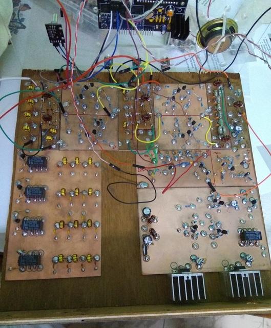
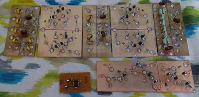
I believe during this process I have read most of the content on bitx20 forum. Some name which repeatedly comes to my mind are Raj (vu2zap), Allison, Jerry and thanks to all other hams out there. I had all the version schematics but started my work based on V5 and wanted to get the best out of all the version so I kept the build approach modular and laying them almost like the schematic for easy troubleshooting (you can see those pic on my qrz page).
Next challenge was trying to be too good student and follow everything the master said (pun intended). I made a cocktail of 12 Mhz with 11.059 Mhz crystal filter (Farhan Sir I believe the schematic is still showing X7 as 12 Mhz) and after changing the X7 to 11.059 Mhz I was able to see the radio signal making it through the crystal filter, then came the next hurdle of fine tuning the USB and LSB and fiddling with the software for the right value. After the receiver started working I took a break from building the radio and started enjoying the receiver and checking all bands. One evening I narrowly missed Farhan ji on air but anyway I would not have been able to communicate with him since my ubitx transmitter was not ready.
After that day I thought of building the ubitx transmitter soon. I was quiet confident about the transmitter build by this time and thought it should be straight forward. Logically yes it should had been that way but I was so wrong. Following all the recommendation from the forum about harmonic issue and how to avoid them I started building the BPF. Then I started to work on the PA section then came tuning the IRF510 current (I call it “Bell the cat moment”) luckily I never blew any IRF510. However, the output watt on 40 M was hardly 2-3 Watts and other higher band less than 1 Watt. I knew something was wrong with those MOSFET but out of circuit the test look normal. I had some other stock from different source even those performed the same. Played around with different PA transformer settings and checking/tracing the RF signal. Everything looked normal till IRF510. Chances of fake IRF510 is less (as debated on the forum) as it is not an expensive RF part like RD16HHF1. Now I was confused, I had some spare new RD16HHF1 which I got online, which I was not very hopeful thinking that it might be fake. I thought of giving it a try (pin layout configuration was easy for me as I have taken the island cutting approach on single side copper board).
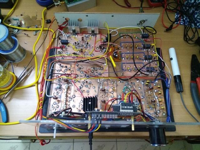
Voila ! I got a whopping 10+ Watt 40M, 5W on 20, 10W on 17M, 10W on 15M, 5W on 12M and 10M. Yes there are lot of fake IRF510 out there. Now it was time to test the homebrew rig on air, checked in at evening into All India Net and got 59 report and the net controller thought I am using commercial rig. Finally during these difficult time in my personal life I was able to smile and sleep well that day. The icing on the cake was installing the Nextion 3.5 display (If I remember correctly this is single most expensive component in the radio and thankfully it is optional).
Does that mean everything is 100% with my home brew ubitx ? Nope, I am still trying to figure out the feedback issue from the speaker during transmit. I traced the issue and found the audio leaking from emitter of Q6. I would like to mention that I tried all the audio circuit and finally settle for TDA2822 circuit. However, the issue is still there during transmit so I have made the audio circuit offline during transmit, I know this will impact my CW listening while transmitting when I upgrade my license . I have exhausted all solutions from Bitx20 forum but still no luck. I would be happy is someone can point me to the right direction. I would be also happy to share any information related to my build or the software settings/tuning, yes I like programming especially ‘C’ so I am comfortable with Arduino programs. I am thinking of building another PA module with IRF510, I personally feel IRF510 (I got the original finally) has made the home brewing so interesting.
 |
| Anthony VU3JVX |
Antuino Filter Analysis
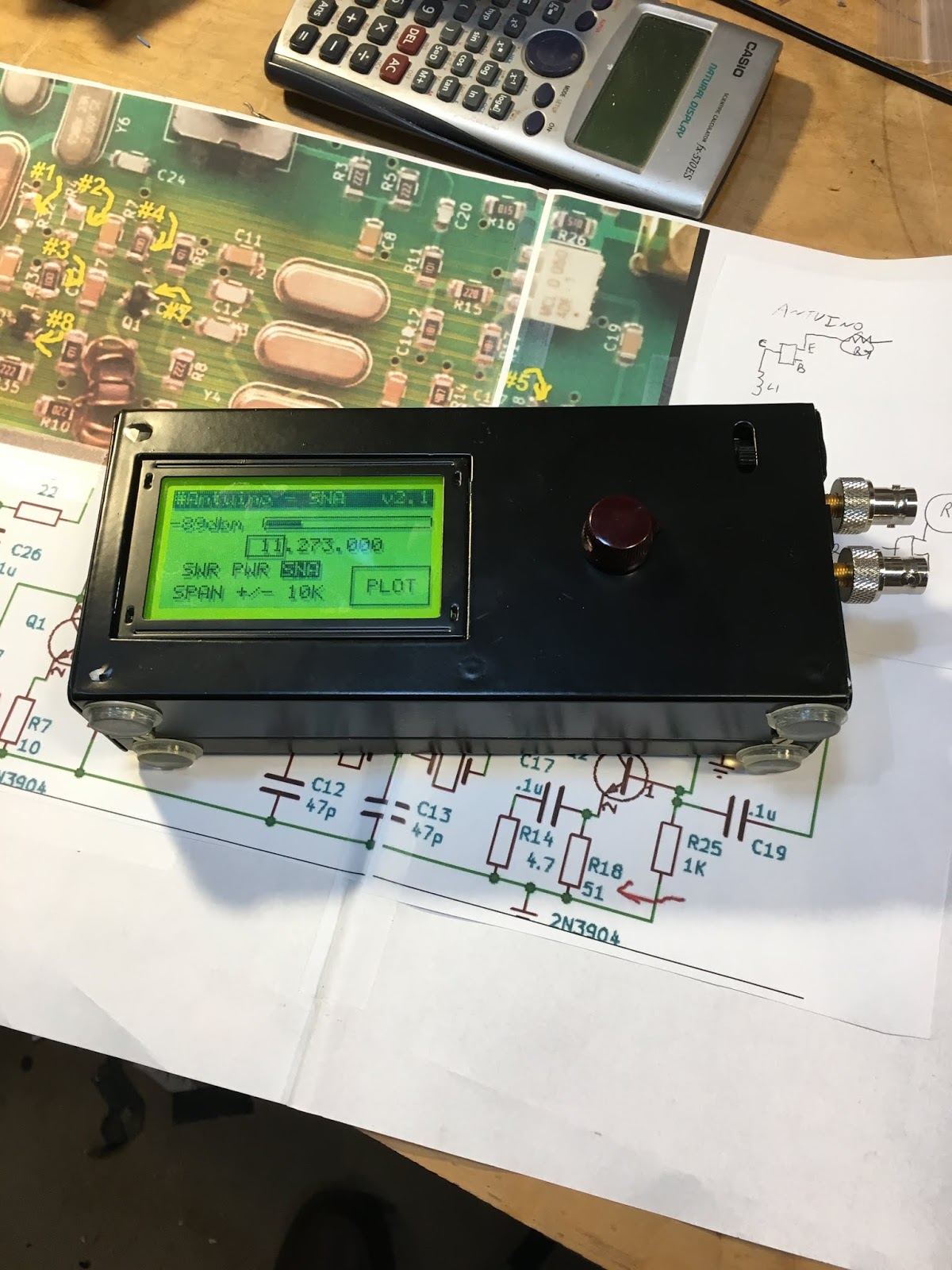
Farhan had given me one of the early Dayton Hamvention models of the Antuino SWR/PWR/SNA RF test lab. He later identified the need for a few mods to improve performance on that early model. So I brushed up on my surface mount soldering, got the needed (tiny!) parts and made the mods. I also put the battery pack inside the box and put some feet on the Antuino cabinet (it just seemed like the right thing to do).
Antuino has already proven to be very useful as an SWR analyzer. I know have a much better understanding of the SWR bandwidth of my wire antennas.
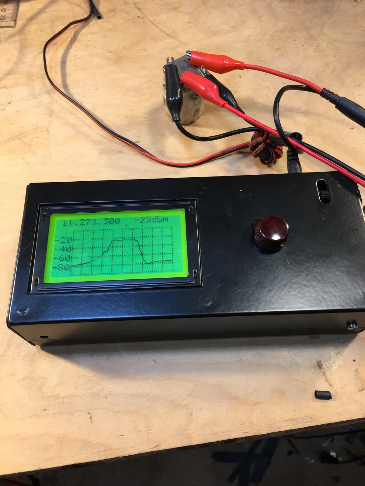
And it is very useful in evaluating the passbands of filters. I had an old 11.273 MHz filter from an old CB radio in my junk box. I have no specs on this device — I didn’t know what impedances it was designed for. So it was time for some Antuino technical detective work.
First, take a look at the filter with nothing between it and the Antuino. Input and output on the Antuino are 50 ohms, so here is what the passband looked like with 50 ohms:
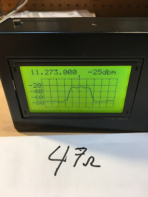
Next I put in two 47 ohm resistors, one in series with the input, the other in series with the output. Antuino connected at the other side of each resistor. Here is what it looked like. Note the improvement in skirt shape. But there is still a lot of ripple in the passband:
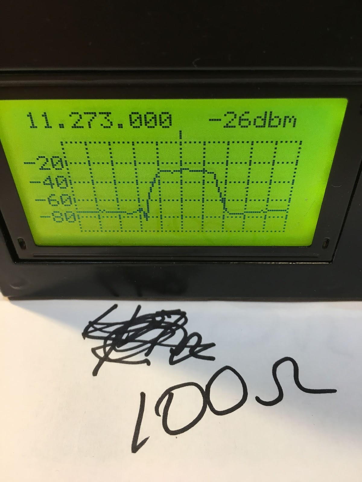
Then I went to 100 ohms. The passband ripple was reduced noticeably:
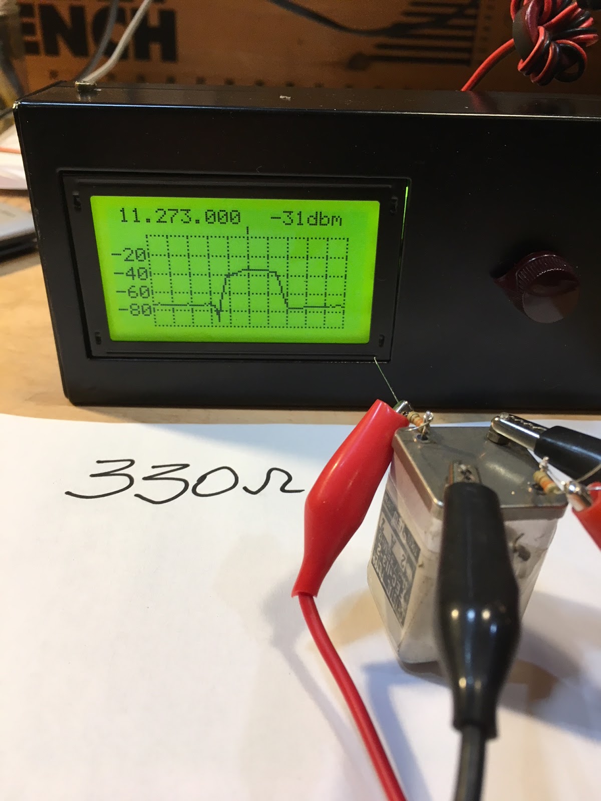
Then up to 330 ohms. Here the passband doesn’t seem quite as flat as it was with 100 ohms:
Finally, 1000 ohms. Definitely too much. Note the ripple.
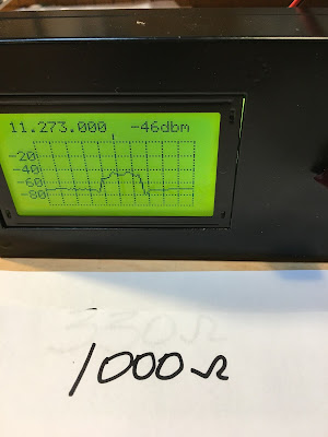
Farhan prefers the passband with the 100 ohm resistors. I agree.
BTW the filter is from TEW of Tokyo, Japan. Model FEC-113-2 11.2735 MHz No. 2 A 2
It had three crystals on the board with it: 11.275 and 11.272 — these are obviously for LSB and USB. The third crystal is at 11.730 MHz, indicating to me that they had a second IF of 455 kHz in this rig. If I use it, I think I’d stay with single conversion. At 11.273 MHz the filter is of ideal passband width for SSB. I do feel the urge to build something around this filter.
Doing the mods on the Antuino was fun, and having worked on the device at least a little bit I feel more of a connection to it.
Follow-Up on Scratch-built BITX17 — Board Map and Video
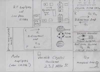
In my last post I put up a time lapse GIF of my BITX 17 build from about six years ago. Above you can see my drawing explaining what each of the stages that you see popping up on the board were. More diagrams here:
https://soldersmoke.blogspot.com/2013/11/bitx-build-update-19-layout-vxo-bal-mod.html
And a lot more info on this build are available on this blog. Just use the search box for build updates (but be aware that this search will also bring up updates on later projects).
https://soldersmoke.blogspot.com/2013/11/bitx-build-update-19-layout-vxo-bal-mod.html
And a lot more info on this build are available on this blog. Just use the search box for build updates (but be aware that this search will also bring up updates on later projects).
Above is a slightly out-of-focus video tour of the board.
I’m posting this stuff partly in reaction to the news that the BITX 40 module is no longer for sale. I hope these posts will serve as a reminder that it is quite possible to homebrew from scratch your own BITX transceiver. This is a fun and rewarding project. Three cheers for Farhan!
SolderSmoke Podcast #214 is FINALLY out!
WE ARE WORKING TO IMPROVE THE AUDIO QUALITY. IN THE FIRST RELEASE OF THIS PODCAST SOME OF THE AUDIO WAS KIND OF MUFFLED. I TRIED TO FIX IT THIS MORNING AND I THINK I MADE SOME IMPROVEMENTS. THE IMPROVED AUDIO IS NOW AT THE LINK BELOW.
4 November 2019 (shockingly late!)
http://soldersmoke.com/soldersmoke214.mp3
The visit of Farhan to Northern Virginia
“I heard this guy from Southern California on 20…”
Fire Report from Pete
Pete’s Bench Report
“When you know stuff, you can do stuff!”
The CRAP rigs
Old Boatanchors — the Swan 120 with SUPER STABLE ANALOG VFO!
Ten Tec rigs dial cord replaced with Chinese digi sig counter
Pete’s 500 mW encounter with a QRO curmudgeon
The ZL2BMI Challenge has Pete building crystal filters
The Left Coast Loafer CW rig
Bill’s Bench Report
ET-2 Refinements
N0WVA’s Regen Receiver
Going from ET-1 to ET-2
J-310s vice MPF-102
100 mW from a single J-310
Receiver kind of deaf -103 dbm MDS
10 contacts so far in 9 states
THREE contacts yesterday.
Worked Wisconsin – 633 miles on 92 mW
We are at sunspot minimum.
“Rage, rage against the dying of the light.”
Simplicity is the real reason for CW
IDEA: Get those Michigan Might Mites on the air!
Use Reverse Beacon Network to see if you are getting out
Use SDR receivers to make contacts
MAILBAG
DL1AJG
KC6SAX
W9VNE
KA4KXX
N0WVA
Zl2BMI
AJ6BD
Farhan Visits Northern Virginia and SolderSmoke HQ
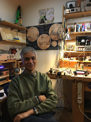
Our good friend Farhan came to Northern Virginia last week for the 50th Anniversary Symposium of AMSAT. We were really delighted that he also came to SolderSmoke HQ. Elisa and I gave him a lightning tour of Washington DC (including a quick visit to The Air and Space museum) and then we headed back to the shack from some radio work.
In the picture above you can see my BITX-20 (that Farhan designed) off his right shoulder. Off his left shoulder you sits my ET-2 rig. I really wanted to show Farhan how well the N0WVA regen performs — he was impressed, especially when we started listening to SSB contacts. It was really amazing that we were doing this with just one J-310 FET. This was great fun. Farhan tells me that he will soon take up the “two transistor challenge.”
When he was here in 2017, I tried to demonstrate my version of Rick Campbell’s R2 Direct Conversion receiver. Unfortunately, when I tried to show off the “single signal” capability that is the whole purpose for this receiver, it was NOT producing a single signal output — you could hear the signal on both sides of zero beat. One of the small AF chokes I had used had gone open, knocking our one of the two DC receivers. This time I had the problem fixed and single signal reception was successfully demonstrated.
Farhan brought me two pieces of test gear that I have needed for a long time: A step attenuator and a two tone generator. Paired with his Antuino, these devices will bring about a big increase in capability on my bench.
It was really great to have Farhan in the shack. We had a great time talking about ham radio and homebrewing. Elisa and I both really enjoyed hearing from Farhan about his travels and about his life in India. We are all really lucky to be in the same hobby as Ashhar Farhan. Thanks for the visit Farhan.
Here is a quick video of Farhan tuning the BITX 20.
Antuino Mods and Updates from Farhan
Both messages from the BITX20.io email group.
26 July 2019
Peeps:
The Antuino has been in use for over a few months now. We had produced 100 of them that were sold at the FDIM. These work quite well for an SWR meter and Antenna Analyzer, but they were sub-optimal for serious RF work. For those who bought it for SWR measurements, you can continue to use it. For those who want to improve it, read on.
It was noticed that the db scale was not accurate. Antuino was designed to be an accurate and precise instrument. The db readings should be within +/- 1 db accuracy. However, they tended to vary by as much as 2 db on the upper range of power measurments. This was finally tracked down to having too much gain. I had prototyped the original with 2N3904 transistors but in production we used BFR93W as I guessed it would have ‘better’ performance. It turned to be a bad choice. The higher gain resulted in compression of signals above -30 dbm. This restricted the useful range of the Antuino to about 50 db.
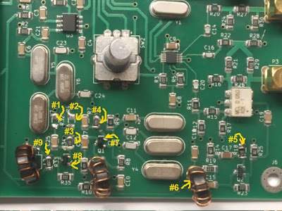
I am attaching the new (Version 2.1, it is a minor edit of the V2 that was sold at the FDIM). In summary, these are the changes:
1. The new software with a cleaner way to calibrate is on https://github.com/afarhan/antuinov2.1. Please upgrade to it even if you don’t want to carry out the other hardware modifications.
2. Replace the Q1 and Q3 transistors to 2N3904. Although the PCB pads are SMT, you can solder the leaded type by twisting the legs around.
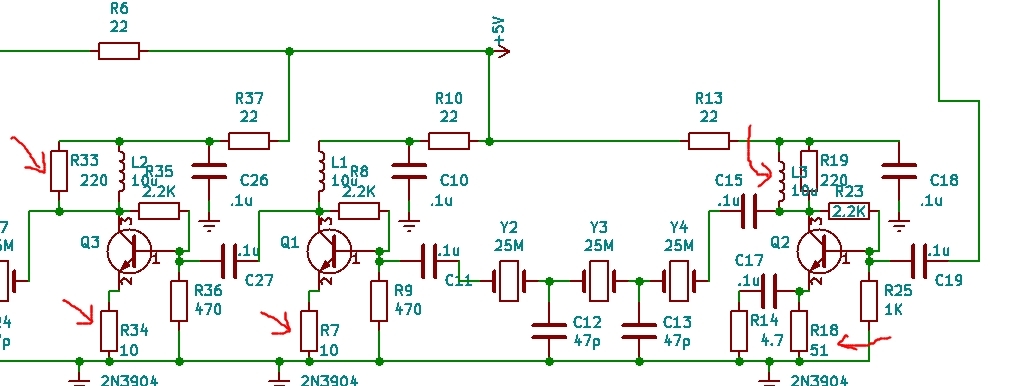
3. In the first IF amplifier (that immediately follows the mixer), we decrease the emitter resistor (R18) from 100 ohms to 51 ohms (you can also parallel a regular 1/4 watt 100 ohms with the original 100 ohms to get to 51 ohms). We also parallel the (R19) 220 ohms collector load with a 10 uh inductor (you can use 10 turns on FT 37-43), the exact value is not important.
4. In the second and third IF amplifiers, we replace the 100 ohms emitter resistors (R7, R34) with 10 ohms and remove the 4.7 ohm resistors (R32, R4).
5. In the last IF amplifier, we change the load resistor(R33) from 51 ohms to 220 ohms.
You need a few 10 ohms resistors and a 220 ohm resistor. You can resuse the R31 at R18.
I have detailed the modifications at http://www.hfsignals.com/index.php/2019/07/26/modifications-to-the-daytonfdim-2019-antuino/
Attached are the images and the circuit.
73, f
_._,_._,_
August 3, 2019
Every instrument has limits on its accuracy. While making the Antuino, I was well aware of its deficiencies.
I made a decision to keep it simple to a point where a radio ham could throw this thing together in an evening or two.
In order to overcome the limitations inherent in the Antuino design, the complexity could have been prohibitively complicated and expensive.
On the other hand, it is an extremely useful instrument that grows on you. I no longer use a frequency counter or the specan. I rarely use the oscilloscope. Antuino does most of my measurements.
There are two very important things you must be aware of while using the Antuino :
1. In the power measurement mode (the problem is non existent on swr or sweep mode), any reading above 25 mhz could be an image. Thus, if you see something at 35 mhz, you will have to do some mental math to figure out if it is not an image. An easy way to know is to add an external low pass filter with 25 mhz cutoff.
You have to use it like a radio in this mode. If you want to measure the harmonics from your pixie radio with 7040 crystal, tune to 14080, 21120, 28160 and measure. It is as accurate as any spectrum analyzer with more than 80 db of usable bandwidth. Raj and I struggled to get this for a month.
2. Unlike a full fledged spectrum analyzer, Antuino has just one bandwidth of about 7 KHz. This is enough to made IMD measurements at 20 KHz tone separation. The sweep plot does only 128 readings. Thus, if you sweep a low pass filter from 0 to 20 mhz, it will measure the filter response every 120 khz. If there is something lurking between the steps, it will miss it. This is a common challenge with spectrum analyzers. So, a crystal filter should be swept at less than 100 khz.
There is a software hack to mitigate this. First : introduce another control for step size. This can slow down the plot. A 30 Mhz sweep at 5 khz steps will involve 30 x 200 =60000 readings.It could take minutes. The Second : write a more optimal Si5351 routine that changes frequencies faster. I know that smaller jumps can be instantaneous on Si5351. I don’t know that hack. If someone wants to take a stab at it, I am willing to work with them.
In a nutshell, Antuino is a very useful instrument. You don’t have to buy it. You can build it. It is just as challenging as a direct conversion receiver. It does a fabulous job though. It can measure oscillator frequencies, it can measure amplifier gain, distortion, frequency response, it can measure filter response, it can show mixer behaviour, it can tune your antenna, it can measure power from a few uV to 100 mv and more with attenuators. It does all this slowly but surely. Like any precision tool, you must know its limitations and use them as an aware user. I would wager that if you have to choose just instrument for your lab, it would be this; Apart from a DVM.
And (I repeat) don’t buy it, build it (grin)
– f

The Fish Soup 7 QRP Rig — On the Air on 40 Meters (video)
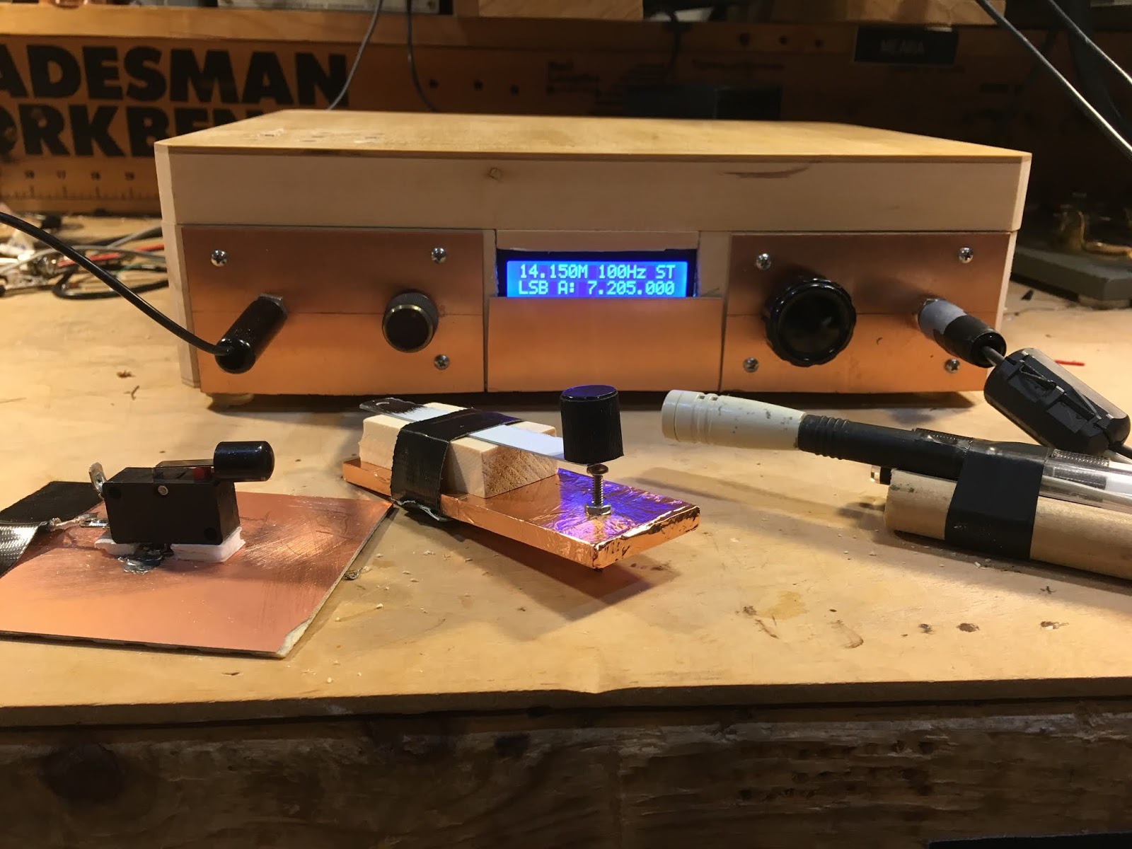
I don’t know why, but this weekend I got the urge to get on the air with a very low power homebrew QRP rig. I reached for my Tuna Tin 2 — Herring Aid 5 combo. I call it the Fish Soup 7 (seven transistors in total).
I first tried to turn this rig into a transceiver by taking the VFO signal from the receiver (it is direct conversion) and using it to excite the Tuna Tin 2, but it just didn’t work out. The oscillator in the Herring Air 5 is very bare bones — no buffering and an LC circuit that is mostly L (10 uH). It became very difficult to get a stable amount of CW offset. So I went back to crystal control for the transmitter. I did replace the 5K tuning pot in the RX with a 10k 10 turn pot (thanks to W8NSA). Tuning is now very smooth. I used my old UK freq counter to monitor my receive freq. (Thanks to Tony Fishpool G4WIF– back in 2009 he sent me the CMOS chip that brought this counter back to life.)
I was putting out about 750 milliwatts.
I had a very quick contest-like contact with K2D — one of the “13 Colony” stations. Then a longer chat with Hank K1PUG (see video above).
I had lost my 7050 crystal, but this morning it re-appeared. TRGHS.
As you can see in the video I am using the beautiful VU3XVR key that Farhan brought me from India.
This was fun. I may try to put a VFO of some sort into the TT2, just to get more agility. But I want to keep things simple.
Look for me on 7050.
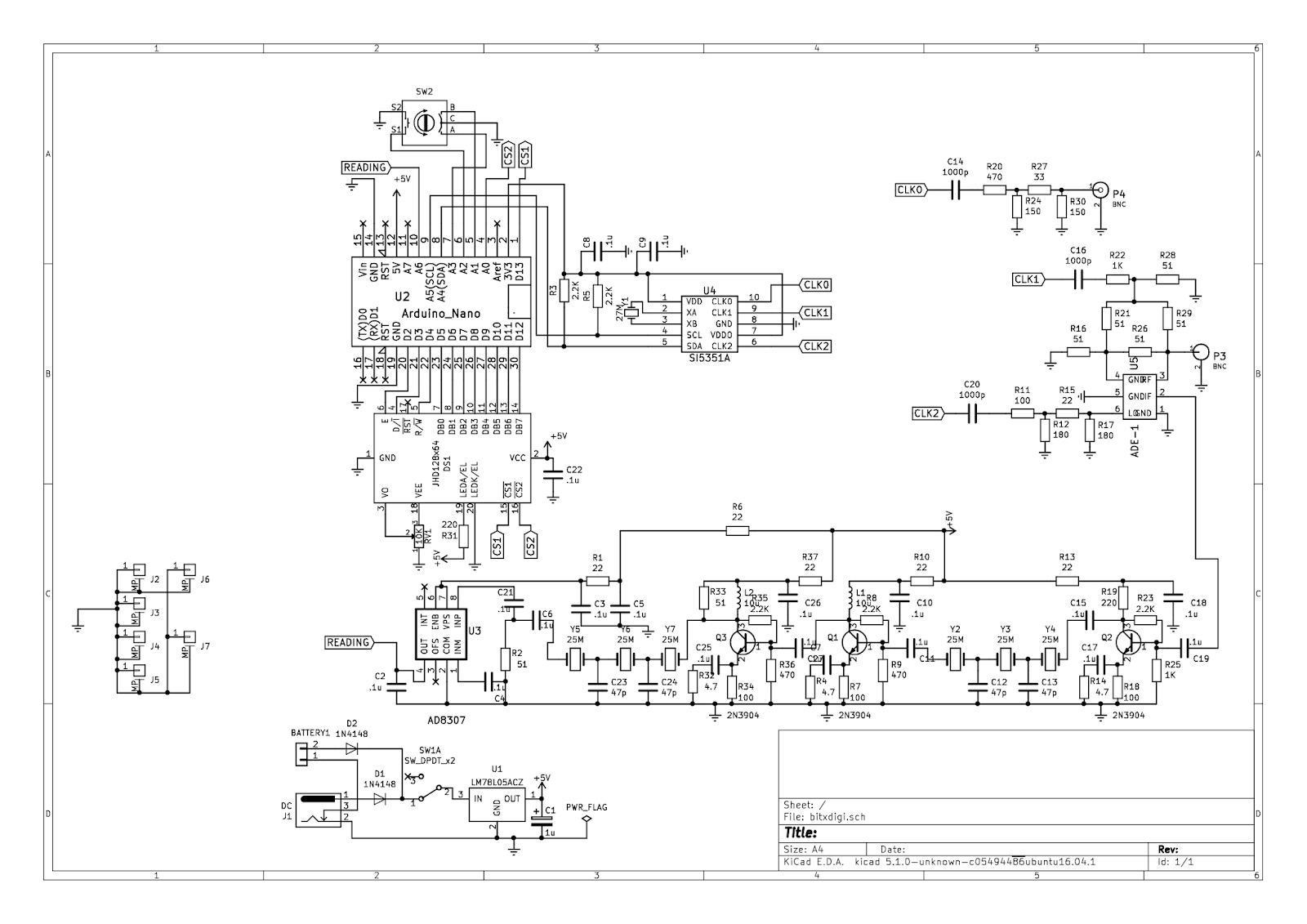
Antuino’s Cubesat Origins, and How it Works (with video)
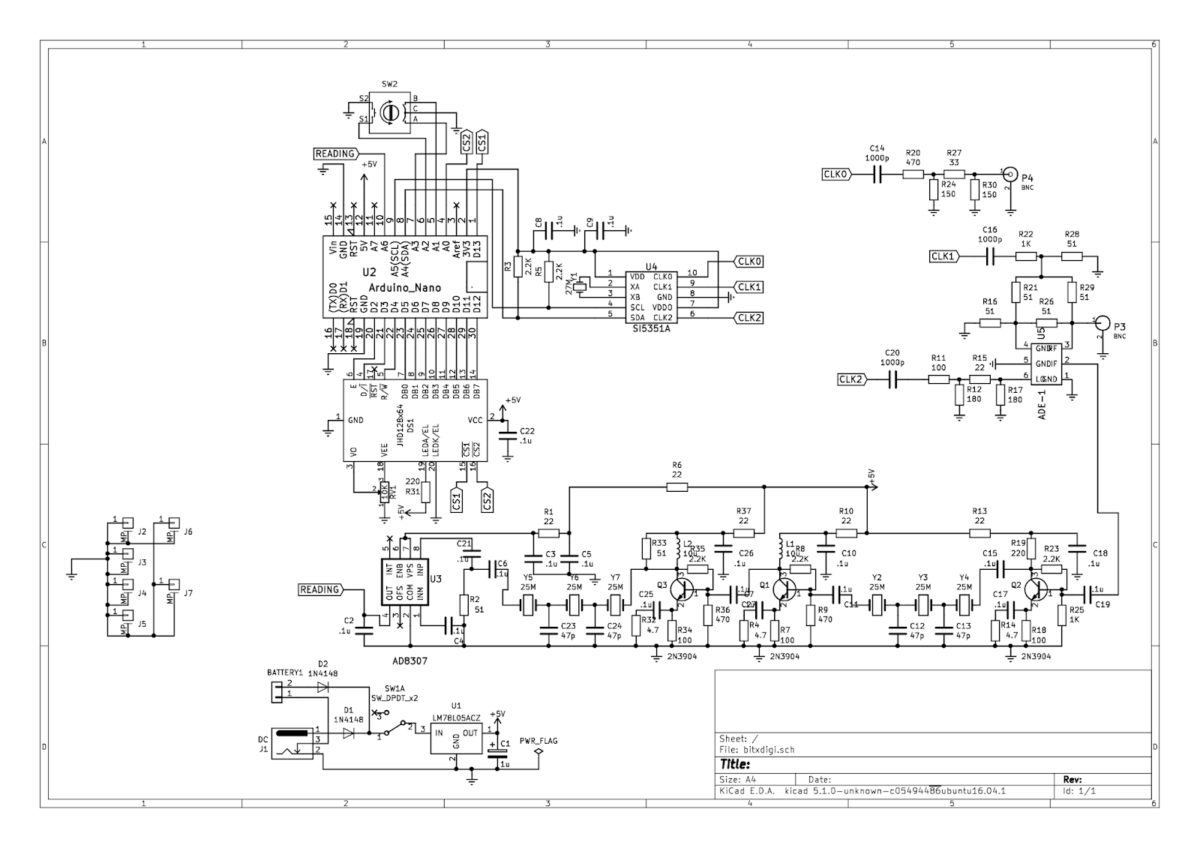
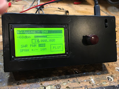
In a series of e-mails to the BITX20.io group, Ashhar Farhan VU2ESE provided background information on the origins of his new “RF Lab in a Box’ — the Antuino. He also explained how the device performs the SWR meter, Power Meter and Scalar Network Analyzer functions.
Farhan’s Antuino Page: http://www.hfsignals.com/index.php/antuino/
Dec 27, 2018 to BITX.io
peeps,
while trying to measure the swr on the cubesats, i figured i couldnt use any of the analyzers i had access to. they were simply too big to be stuffed inside a 10 cm cube. my simple resistive bridge was too insensitive for any reasonable work. so, i sat down and made an antenna analyzer from a spare raduino.
the code is wobbly and just about enough to get my work done. it works on a superhet principle. this is not my clever idea, rahul had mentioned this approach taken by a russian builder. i havent seen the original design. it would be interesting if rahul or someone can point me in the right direction.
the code and a pdf of the circuit is on https://github.com/afarhan/antuino. i am attaching the circuit for the lazy bones.
have a great holiday and get some dx !!
– f
Dec 28 2018
Jerry,
first, thanks. there is substantially your code in there.
second, onto the circuit. it uses two clocks. not three. the third is a spare output. more on that later.
the circuit here uses a resistive return loss bridge. the clock 1 drives the bridge through the R22 to a low level of -10dbm. If the bridge is perfectly balanced (that is, the antenna, R21, R29, R16, all the four are the same ohms), then, there will be no RF developed across pins 3 and 4 of the ADE mixer. Under ideal match conditions, there is no RF across the R26. As the mismatch increases, so does the RF across R26.
We could directly detect the voltage across the R26 with a diode detector. This is quite a popular configuration with most of the simple resistive kind of SWR bridges (like the one designed by Dan Tayloe). This simplicity comes at a cost. The problem is that the detector responds to all the RF between the arms. For instance, if another ham down the block starts to transmit, that energy will show up across the R26 and you will get crazy SWR. I had that problem with broadcast FM showing up on my 7 MHz dipole! Even if there was no RFI from elsewhere, harmonics and spurs from your own transmission can show false readings.
Here is an example: a 7 MHz transmitter with a 14 Mhz harmonic that is 20 db down is connected to a 7 MHz dipole. The dipole is perfectly tuned to show 1:1 SWR, hence, it should show no RF across R26. However, as the antenna is reflecting back the 14 MHz energy, the 14 MHz shows up across the R26.
What’s the solution to get a clean dip?The solution is to substitute a simple detector like a diode detector with a simple receiver that is tuned exactly to the frequency that you want to measure the antenna at.
So, the ADE-1 mixer, Q2, Q1 together form a very simple superhet receiver with 25 MHz IF andCLK2 as the local oscillator. The RF at the IF is directly detected and converted to db range with the AD8307. This simple configuration makes this a very powerful instrument.
Here are things you can do with it:
1. Switch off the CLK1, now you have a receiver that can very accurately measure RF levels at any specific frequency in db range. For instance, you connected your transmitter with a suitable RF attenuator to P3, you can tune to various harmonics and measure them very accurately. If you inject a two tone signal into an amplifier, you could easily measure the IMD and IIP3.
2. With the CLK1 on, the instrument now measures the return loss. you can measure the SWR of an antenna, S11 parameters of an amplifier, filter, etc.
3. With CLK1 off, CLK 2 on, the CLK2 can now tune to the frequency tuned in by the receiver’s LO (CLK0). By connecting a device/filter between P3 and P4, you can sweep it to measure the gain, frequency reponse.
4. As the diode mixer (ADE-1) has harmonic response, a local oscillator at 135 MHz, will also convert a 430 MHz signal into 25 MHz IF (430 – (135 x 3)). This is possible because we are driving the diode mixer with a square wave from the Si5351 and the local oscillator at 135 MHz also has a 405 Mhz harmonic in it. Hence, the range of this instrument extends to UHF.
The ADE-1 mixer is quite similar to the ubitx mixers. You could even use ubitx kind of discrete version of a diode mixer, it doesn’t work too well beyond 50 MHz. The pins 4 and 3 of the ADE-1 are the primary winding of the RF-input side transformer. The documentation recommends that we must ground 4, but that is not essential. We need a differential drive between those two pins, that is what the bridge provides anyway.
73, f
jerry,
i built it so i could stuff it inside the cubesat to measure the antenna. an external spectrum analyzer and its cables were upsetting the RF model hence, i needed something that could read the return loss sitting inside the cubesat. then, i borrowed by daughter’s DSLR with a monsterous tele lens and sat 100 meters away to read the the LCD display as it swept through the range.
the analyzer was removed once we knew the correct dimensions and the actual payload went inside the bird.
– f
SolderSmoke Podcast #212 HDR, Boatanchors, SDR, Antuinos, Spurs, QSX, Mailbag
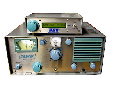 |
| Dale Parfitt W4OP’s SBE-33 with modern digi freq counter |
SolderSmoke Podcast #212 is available:
http://soldersmoke.com/soldersmoke212.mp3
22 June 2019
CONGRATULATIONS TO PETE: Licensed 60 years today
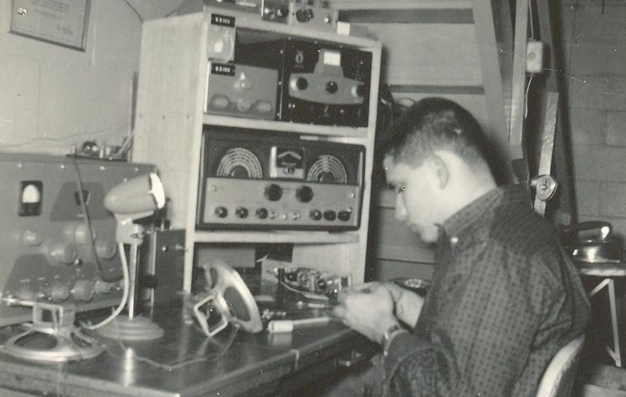 |
| Pete Juliano during Field Day, 1959 |
Sideband Engineers Models 33 and 34 — Thanks Pete!
Hans’s QSX SDR Rig at Dayton-Xenia and FDIM
W8SX FDIM interviews
Pete’s SDR Projects — Update
The Peregrino SSB transceiver in the summer SPRAT
Why no rare earth cell phone speakers in ham projects?
My HDR “waterfall” project
Farhan’s Antuino
Cubesat origins
RF Lab in an box
SWR, PWR, SNA
Superhet receiver with ADE-1 at front, and log IC at the output
Adapters (SMA to BNC) help
DON’T BLOW UP THE INPUT RESISTORS (LIKE I DID!)
My dirty DIGITIA — Denial, then acceptance
FFT
Useful programs: SPURTUNE and ELSIE
A better bandpass filter for the DIGITIA
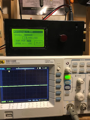
The importance of a good test set up with Antuino
Manassas Hamfest: WA1UQO, W4WIN, AI4OT
MAILBAG:
KG7SSB
WA3EIB
VK4PG
W3BBO
Jeff Tucker — Who owns Drake 2-B #4215?
KN4BXI
KC5RT
K3ASW
Face the TRUTH! LOOK at Your Signal with an Antuino!
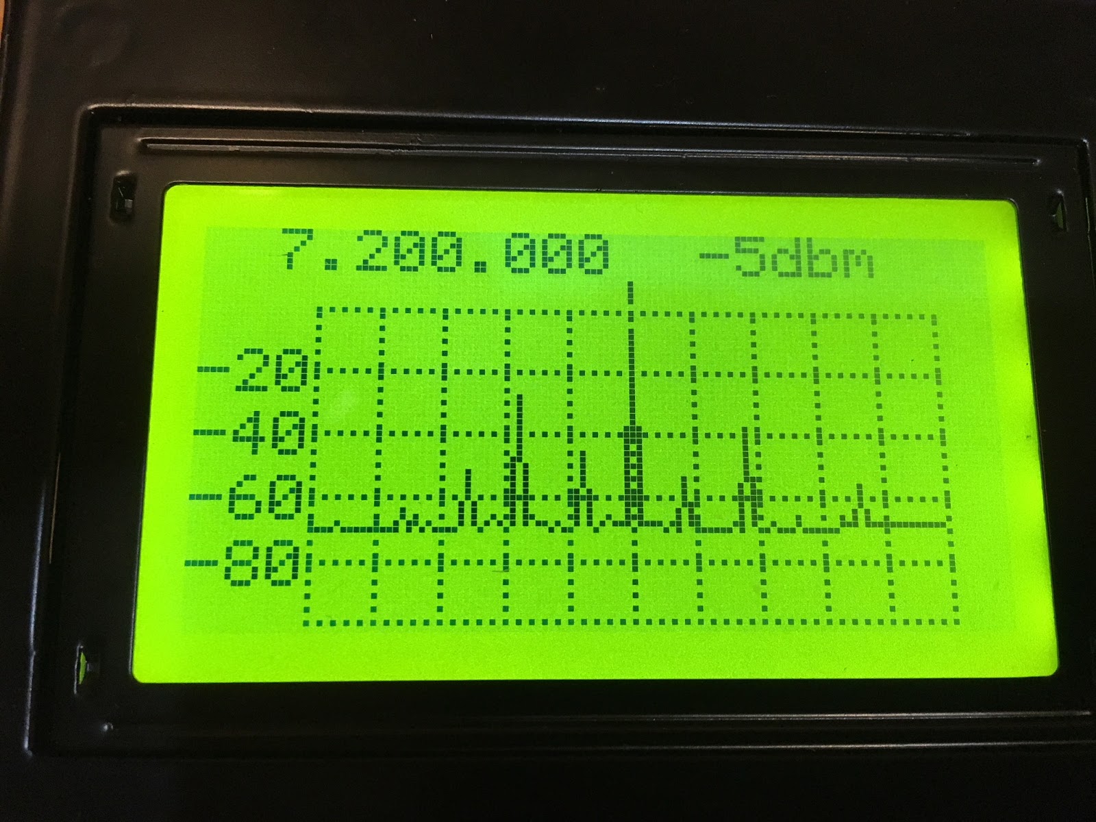
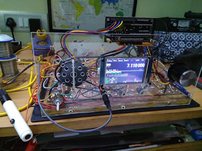
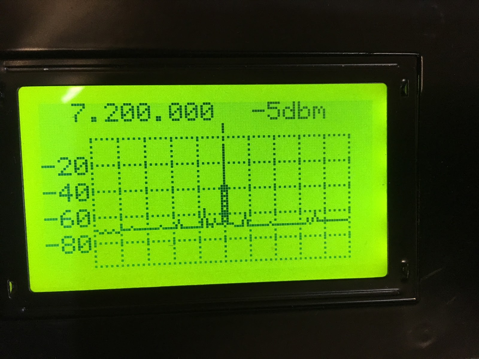
At first, I didn’t want to believe it. I was in denial. I wanted to shoot the messenger (in this case, the Antuino). How could my beloved HB 40 meter DIGITIA transciever have an output that was so…. so DIRTY! Everyone tells me it sounds great. But the little Antuino screen told a different story. Strong spurs up at 9 MHz and down at around 5.4. And lots of places in between. (In these display images, the center frequency is 7.2 MHz and each division to the left or right is 1 MHz.)
Farhan tried to get me to face the truth: “The frequency domain viewing of RF Signals is the opening of the third eye. Once you start seeing signals as a bunch of simultaneous sines, you will always be wary of the waveforms on the scope. In fact, time domain readings make little sense.”
At first I blamed strong VHF RFI and my somewhat hay-wire test set up. My homebrew Rube Goldberg 20 db attenuator was probably picking up some of the VHF RF. But as I looked more closely at the output of the transceiver in the frequency domain, I gradually accepted that it was true. There were a lot of spurs. I have a general coverage receiver in the shack, and with it I could hear the little devils. And after some adjustment I could see them in the FFT display on my Rigol o’scope. An exorcism was definitely needed.
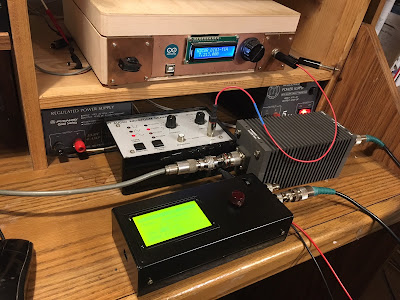
But first came a tightening up of the test setup. Pete advised me to do this. I had in the shack some really nice dummy load/attenuators from the HP8640B Signal Generator that Steve Silverman had given me (and that Dave Bamford had hauled across New York City for me). I ordered the necessary N connectors and adapters and soon my test setup improved a lot.
All this got me thinking about spurs. I consulted EMRFD and was reminded of a really great program in the LADPAC software pack that came with the book. The SPURTUNE program predicts spurs and tells you what to look out for. It is really illuminating. Try SPURTUNE.
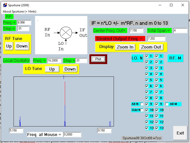
Through this, I gained a better appreciation of the importance of the bandpass filter in an SSB transceiver. I’d always thought of it as something that allowed the other mixing product to be eliminated while passing the one you want. But I came to realize that it does a lot more than that — it also helps get rid of spurs. If it is designed right. Mine was not. I had plucked it out of an old QST article and had not paid much attention to it. All it needed to do was knock down the unwanted mixing product, right? And in my transceiver (9 MHz IF, VFO running 16.0 – 16.3) MHz that unwanted product would be way up at 25 MHz. It wouldn’t take a lot of selectivity to knock that down. But I’d forgotten about the closer-in spurs. Antuino reminded me of them. And SPURTUNE explained where they came from.
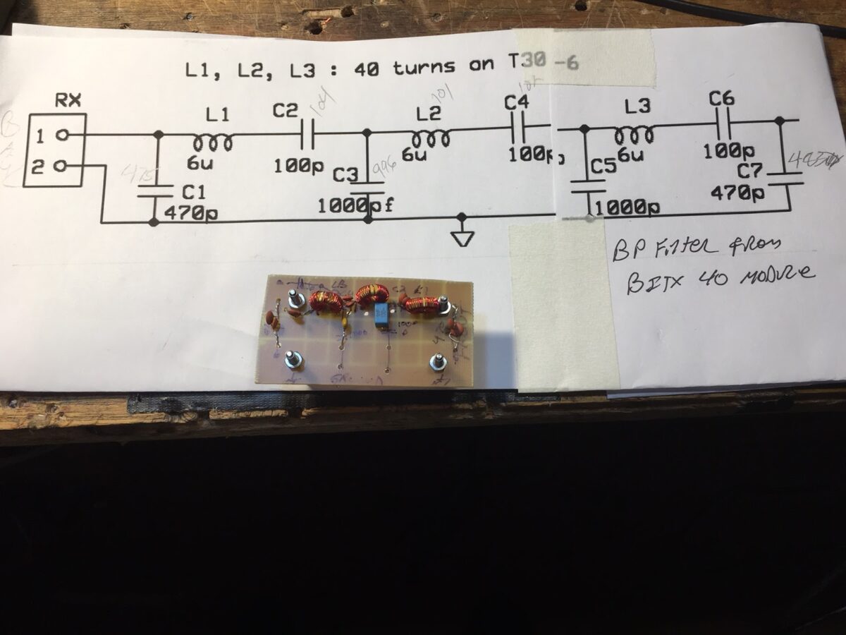
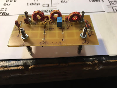
For the exorcism, I decided to use the bandpass filter design from Farhan’s BITX-40 Module. I had made the BP filter on this rig “plug-in” so it was easy to build a new filter.
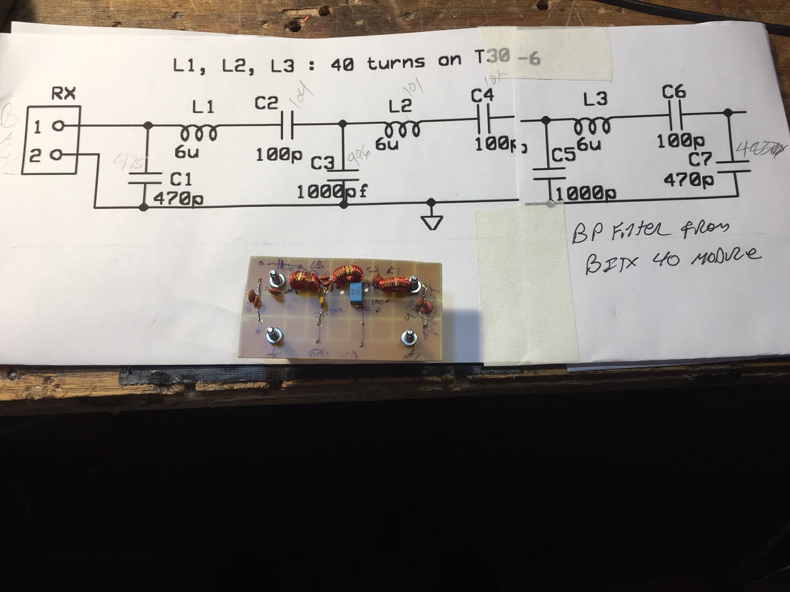
I even checked out the filter design in a simulator. For this I use ELSIE. Another very useful program. Here is what ELSIE predicted for Farhan’s BITX40 Module filter:
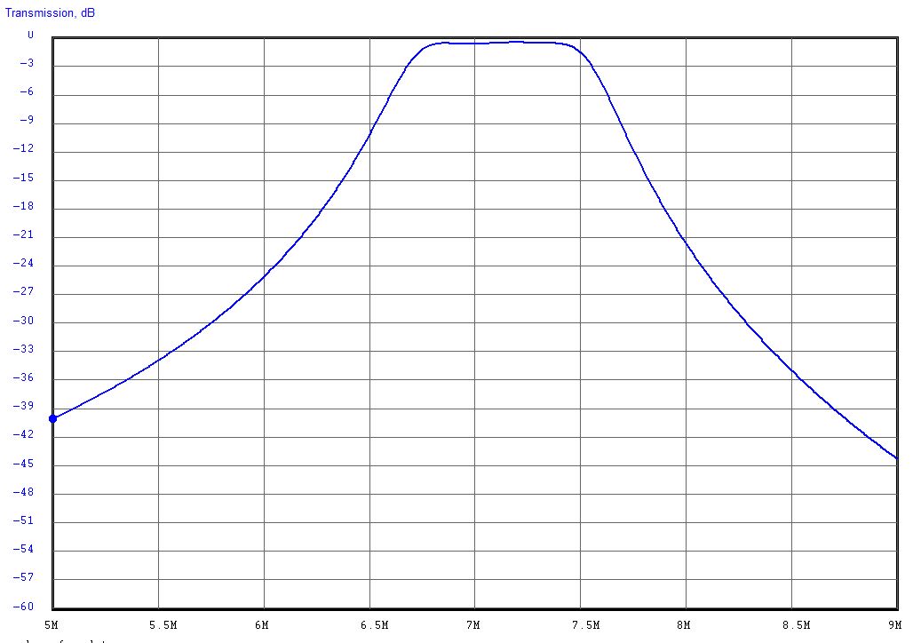
I plugged the new filter into the DIGITIA and… SUCCESS! The big spurs that were bothering me were gone and the remaining spurs were all below 50db down from the main signal. Here is what it looks like now:
The Antuino is a very useful device. You can learn a lot from it, but you have to realize that this is not plug and play radio. You have to think about what you are testing, make sure you have the test gear set up properly, think about the circuit you are looking at, and be careful not to put too much RF into the device.
Three cheers for Farhan and his new Antuino! More on this soon. And we will talk about this on the next podcast.
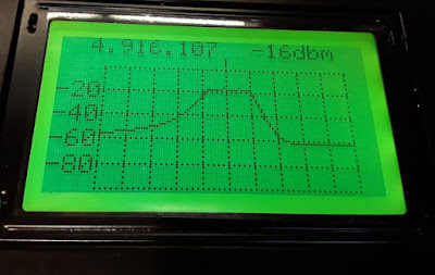
First Use of Farhan’s Antuino Scalar Network Analyzer
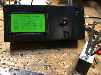
I was learning my way around Farhan’s new Antuino this morning. Very cool. I decided to start with the Scalar Network Analyzer. I’ve spent so much time measuring and plotting filter response curves BY HAND… the Antuino is an opportunity for me to move into the 21st Century.
In the picture you see the results. I was using a Heathkit SSB filter with the center frequency at 3.395 Mhz. The Antuino was set for that freq, with the screen range set at +/- 10. That means each division on the screen is 1 khz (right?). The Heath filter is advertised as being 2.1 khz wide at 6 db down. That pretty much matches what we see here.
You can see ripple in the filter passband. This is almost certainly the result of an impedance missmatch. It looks to me like the Antuino is set up with 50 ohm inputs and outputs. The Heath filter probably needs higher impedances to have a smooth passband. I will try later to set it up for a smooth passband.
It is easy to see how useful this device will be. Thanks Farhan!
More on the Antuino here:
FDIM Interview with Farhan VU2ESE
I didn’t realize that our correspondent in Dayton/Xenia had interviewed Farhan. There was a typo in the audio file name and I was wondering who this UV2ESE guy was. A Ukrainian QRPer? I was really pleased to find out that it was Farhan.
In Bob’s interview you will hear Farhan discuss the capabilities of his new Antuino (pictured above). Pete’s Antuino is in the mail, going transcontinental. It should arrive in the Newbury Park Laboratory later this week.
As for the spectrum analyzer that Farhan got me last year, I am waiting for retirement (soon!) to get that one going. But there is a danger that the Antuino will leave little room for the older tech…
In the interview you will hear Farhan talk about the Antuino circuitry, and about the roots of the three main devices in the Antuino box. Very cool.
Thanks again Farhan. And thanks Bob.
Here is the interview:
http://soldersmoke.com/VU2ESE FDIM 2019.m4a
Farhan’s Antuino page:
http://www.hfsignals.com/index.php/antuino/
Antuino: Farhan’s Compact RF Lab In-a-Box
I now have Farhan’s latest invention, the Antuino. Pete will have his shortly. Very cool. SWR meter and antenna analyzer, power meter and scalar network analyzer all in one box. I put an old-school knob on the rotary encoder — it seemed like the right thing to do. Soon I will be able to find out if my rigs have spurs or are somehow non-compliant. I’m sure Farhan’s “RF Lab in a box” will be an important addition to my test gear arsenal. We will be talking about this in upcoming podcast episodes.
Mike N2HTT did a nice write up of the new device:
https://n2htt.radio/2019/05/26/hello-antuino/
And here is the info from the htsigs.com page:
http://www.hfsignals.com/index.php/antuino/
Thanks Farhan!