
Here is Farhan’s amazing presentation to the virtual 2021 FDIM event. There is a lot of tribal knowledge in this video. Lots of old and new technology. I was especially intrigued by Chris Trask’s Kiss mixer. Farhan’s discussion of simple Arduino-based speech equalization and compression made me think that I have work to do in this area. And of course, Farhan’s whole discussion of how to bring SDR into — literally into — the circuitry of a uBITX is really cool and very educational.
Category: Farhan
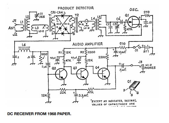
The SST QRP Transceiver
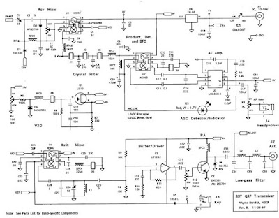
Click on the schematic for a better view
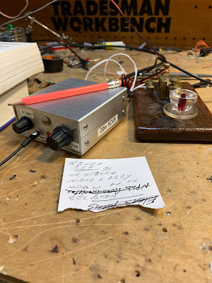
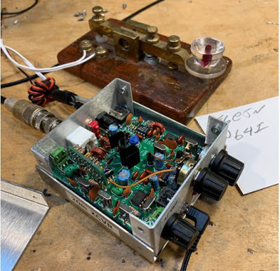
Bob KD4EBM recently sent me an amazing package of radio goodies. Included was a little metal box not much larger than a deck of cards. It is a 20 meter SST transceiver designed by Wayne Burdick N6KR during the late 1990s. This transceiver is built around three NE602 Gilbert Cell mixer chips. It arrived in my shack as I was struggling to understand the Gilbert Cell. TRGHS. It also put me back on the path of QRP CW righteousness. Thanks Bob. Thanks Wayne.
I e-mailed Wayne Burdick (now of Elecraft fame) to tell him I was now using the rig he had designed so long ago. Wayne e-mailed back, saying that the SST was the smallest “real” radio that he had ever designed. SST stands for Simple Superhet Transceiver.
I’ve been using the SST every day for the last week or so. It is a pleasure to operate. I’m using it with the key from India that Farhan brought for me. It is truly QSK — the receiver stays on when I transmit. I’ve never used a QSK rig before and I can now see the big advantage that this provides: When I am responding to a CQ, I can immediately hear if the other guy put out another CQ or respond to someone else — I can stop calling at that point. My first contact with it was with F6EJN. Again, TRGHS.
I made two small mods to the SST: I added 1 uH to the RFC in the VXO; it now tunes 14.053 — 14.063. And I took out a noise blanker that had been installed. Removing the noise blanker left an ugly hole in the front panel which I promptly filled with a completely cosmetic machine screw.
Here’s the manual:
https://qrpbuilder.com/wp-content/uploads/2017/04/sst_manual_042217.pdf
SolderSmoke Podcast #229 — G2NJ Trophy, SDR, HDR, CW! Mailbag
Soldersmoke Podcast #229 is available:
http://soldersmoke.com/soldersmoke229.mp3
— G2NJ Trophy is awarded to Pete Juliano, N6QW.
— Get your vaccine shot as soon as you can!
— More from “Conquering the Electron” by Derek Cheung.
— Bad fire in the chip factory. Such a shame. Sad! I had NOTHING to do with it. I was home that day. I can prove it.
— Bezos is not such a bad guy. Turns out he is a space-geek.
— Perseverance was the big space news. Very cool.
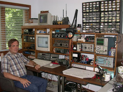
Pete’s bench:
Raspberry Pi vs. Microcontrollers
Treedix display
Conversion of the Dentron Scout
CW rigs?
6L6 on a wooden chassis
SHAMELESS COMMERCE DIVISION-
I NEED TO BUILD UP TIME VIEWERS VIEW MY VIDEOS: So please watch!
https://www.youtube.com/channel/UC20TcdWSSFliMhg3k2A1a5w
— Our Patreon sponsors get an early look at our YouTube content. So please, consider
becoming a Patreon sponsor.
— Please continue to use the Amazon search engine on the blog page (upper right).
Bill’s bench:
Hodgepodge:
— BITX40 Module.
— Ramseykit Amp.
— San Jian counter,
— CW using 750 Hz oscillator.
— RF-actuated piezo buzzer.
— SDR! SDR using PC and tablet.
— Checking the output with SDR.
— Moving the carrier osc frequency.
Also, I put the Fish Soup 10 back on the air. Nice contacts under 200 mw.
Up next: A rig for 80/75 and 20 meters. Single Conversion. Using VFO from a Yaesu FT101 that runs 8.7 – 9.2 Mhz. Quiz question: What IF should I use?
MAILBAG
Mark Zelesky sent me wood tokens with power and Ohm’s law formulae. Thanks!
Scott WA9WFA Built a really nice Mate for Mighty Midget RX – getting it going!
Tryg EI7CLB found board of his George Dobbs Ladybird RX. Rebuild it OM!
Tom WX2J – We talked about “No lids, no kids, no space cadets” nastiness.
Nick M0NTV about sideband inversion. I like the simple rule about subtraction.
Jonathan M0JGH – Always listen to Pete. Got married, has mixing product. Leo?
Mike AE0IH. Dad used a BC-348 in the service. Looking for one. FB.
Adam N0ZIB – “Silent Shep” site — with some ham radio shows I had not seen.
Walter KA4KXX in Orlando has a similar subtraction problem with San Jian counter.
Bill N5ALO sent me a really nice KLH speaker. I’m using it now.
Jason N2NLY – interested in building SSB transceiver. One step at a time OM…
Trevor in Annapolis sent xcsd cartoon that really hit home.
Farhan is doing OK in India, diligently protecting his family from the virus.
Peter VK2EMU also doing well.
Dave AA7EE Casually killed a DC receiver in Hollywood, and disposed of the remains.
Charlie ZL2CTM doing great things with simple SSB. Blogpost.
Phil VK8MC in Darwin sends article on “Mend not End” battle against planned obsolescence.
Bob KY3R re my SDR adventures, asked if I’ve had a recent medical/psychiatric evaluation.
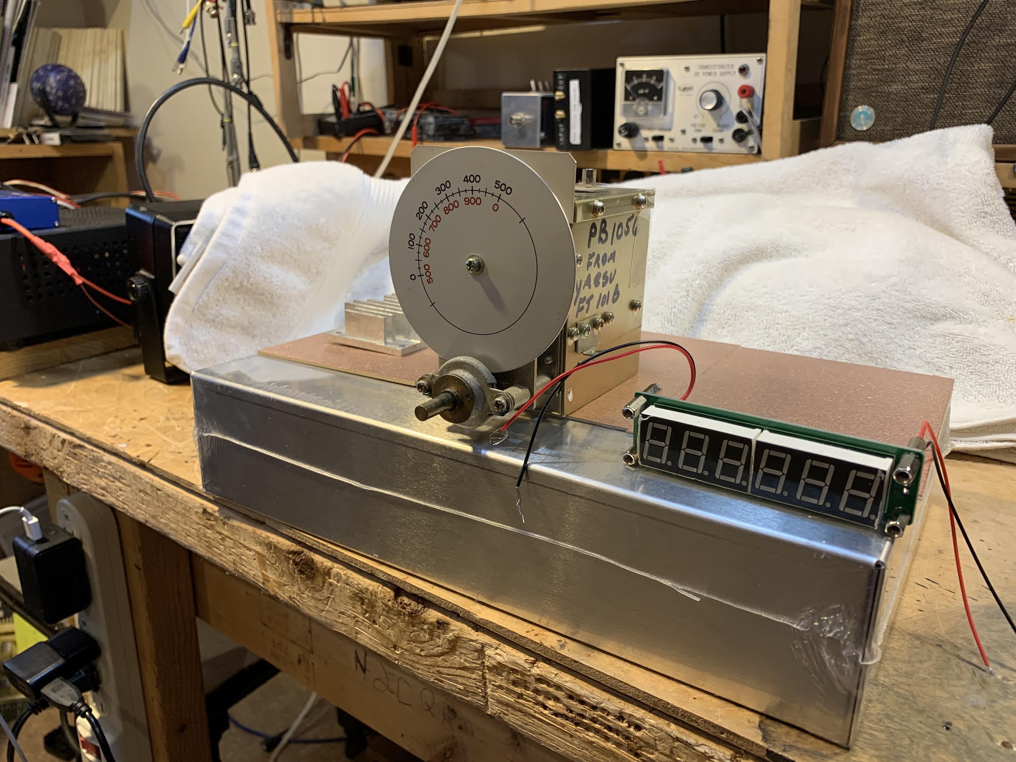
Hodgepodge: Moving the Carrier Oscillator Frequency (and a Flashback to 2002) (Video)
As explained in the video, in the course of using my RTL-SDR dongle I noticed that the signal being put out by my Hodgepodge rig had some problems. There was poor opposite sideband rejection, and in terms of audio quality I has putting out too many lows and too few highs. I figured the problem was the result of the carrier oscillator frequency being a bit too low, a bit too close to the flat portion of the crystal filter passband. I needed to move that carrier oscillator frequency up a bit.
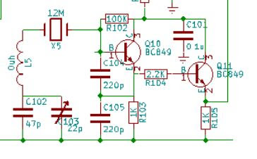
BITX40 Module BFO
In the actual BITX40 Modules, L5 was replaced by just a jumper wire, and the C103 trimmer was not on the board. Farhan and his team instead selected X5 crystals to match the passband of the 12 MHz crystal filter. Mine was originally at 11.998653 MHz. But I wanted to tweak mine a bit — I wanted to move it up about 500 Hz. Reducing the capacitance would move the frequency up. Putting capacitance in series with C102 would have the effect of reducing the capacitance in the circuit. I just removed the jumper wire and used the holes for L5. First I put in a single 30pf capacitor. This dropped the capacitance between X5 and ground to 18 pf. That resulted in too large a shift. So I added another 30 pf cap in parallel with the first one. This resulted in a total capacitance from X5 to ground of 26 pf. This was about right — the carrier oscillator/BFO frequency was now 11.9991 Mhz. I had moved the carrier oscillator frequency up by 447 Hz — just about what I was hoping for.
This was a very satisfying fix. it was a chance to put to use experience with other SSB rigs, to make use of the RTL-SDR dongle as a diagnostic tool, and to tinker with the BITX40 Module in the way that Farhan had intended for it to be tinkered with.
I’d done this kind of adjustment before, but without the benefit of an SDR display. Below is the story of one such adjustment.
———————————
A Flashback to 2001-2002
(From my book “SolderSmoke — Global Adventures in Wireless Electronics”)
Now it was time for some debugging and fine tuning. I needed to make sure that the frequency of the carrier oscillator was in the right spot relative to the passband of the crystal filter. If it was set too high, the filter would be chopping off high notes in my voice that were needed for communications clarity, and it would allow too much of what remained of the carrier (residuals from the balance modulator) through. If it was set too low, the voice signal transmitted would be lacking needed base notes. I didn’t have the test gear needed to perform this adjustment properly, but my friend Rolf, SM4FQW, up in
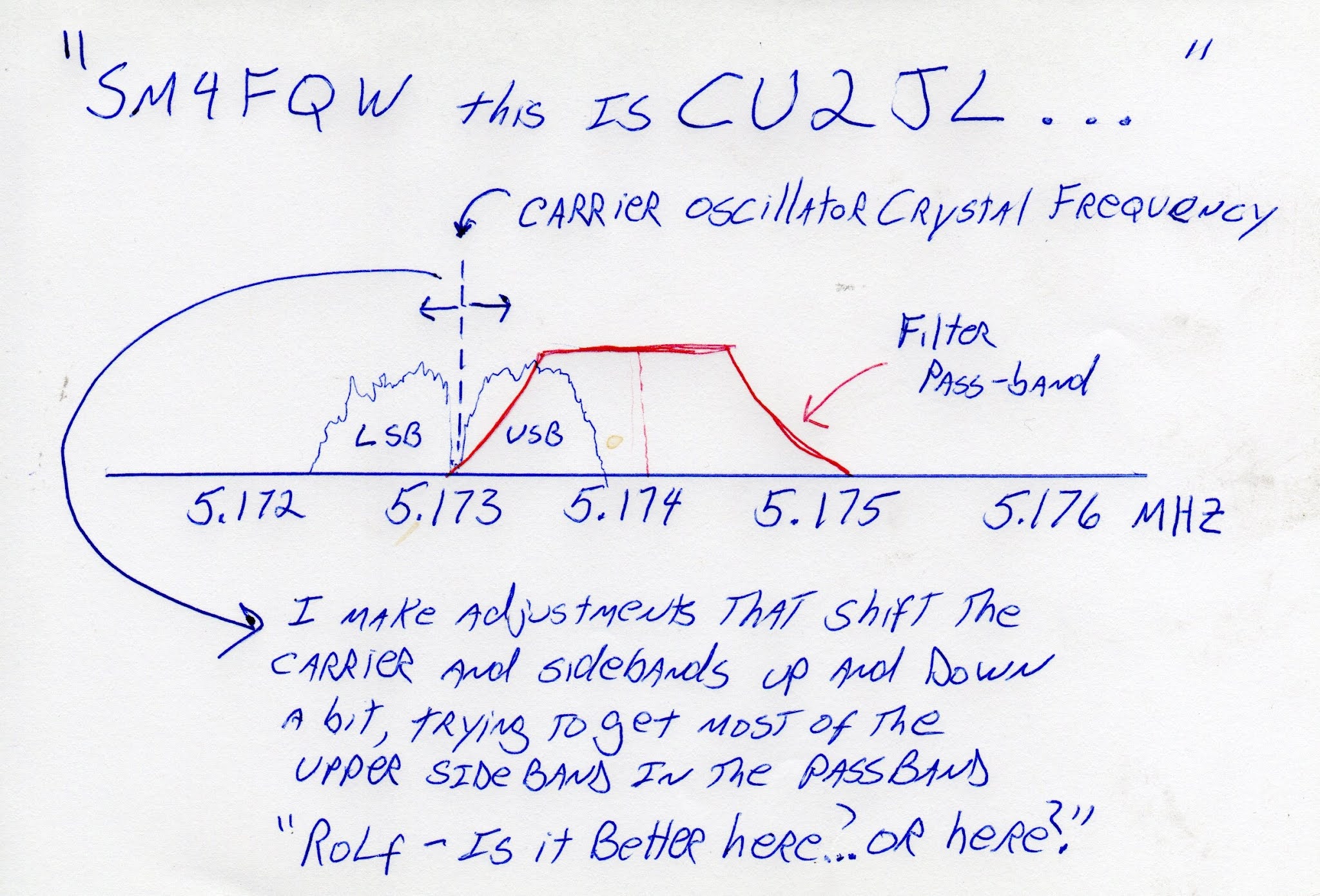
One night, during a conversation with Rolf, I explained my problem and he offered to help me make the adjustments… by ear. Performing an electronic version of open-heart surgery, with power on and Rolf on frequency, I opened the case of the new transmitter. The carrier oscillator has a small capacitor that allows the frequency of the crystal to be moved slightly. With Rolf listening carefully, I would take my screwdriver and give that little capacitor a quarter turn to the right. “Better or worse?” I would ask.
I think this little adjustment session captures much of the allure of ham radio. There I was, out in the
Some Thoughts on Singly Balanced Mixers with Two Diodes and One Transformer
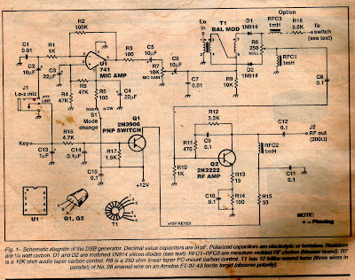
In 2001, out it in the Azores, I built a 17 meter version of Doug DeMaw’s Double Sideband transmitter (“Go QRP with Double Sideband” CQ Magazine, February 1997). I struggled to understand the balanced modulator — how it mixed, balanced, and how it produced DSB. I later presented my understanding of the circuit in my book “SolderSmoke — Global Adventures in Wireless Electronics” pages 132-137. In essence, I figured out that you had to think of the balancing and the mixing as two separate operations: The transformer provided the balance that eliminated the carrier (the LO signal) while the diodes presented the two signals (audio from the mic amp and LO from the VFO) with a highly non-linear path. The LO was successively turning on both diodes then turning off both diodes. The audio signal was being “chopped” at the rate of the LO. This produced a complex waveform that contained sum and difference frequencies — the upper and lower sidebands. The carrier was balanced out by the transformer because the two outputs of the transformer were always of opposite polarity, and they were joined together at the output of the mixer.
Fast forward to 2013. I built a 17 meter version of Farhan’s famous BITX 20 rig. Above you can see the balanced modulator stage, which also serves as the product detector. As you can see, it is essentially the same circuit as the one used by Doug DeMaw in his DSB rig.
In 2018 I built a simple direct conversion receiver for my nephew. For the mixer I used what I considered to be just a cut-down version of the circuit used by DeMaw and Farhan. I got the idea for this from Olivier F5LVG and his RX-20 receiver from SPRAT. It had the RF signal coming in on L1 and the VFO signal coming in to the wiper of the 1 k pot. But with this arrangement, the diodes were NOT both being turned off on half the VFO cycle, then both being turned on during the other half. Instead, as the VFO signal swung positive, D2 would conduct and D1 would shut down. When the VFO signal swung negative, D1 would conduct and D2 would shut down. It worked, but the diodes were being switched in a very different way than they had been in the DeMaw and Farhan circuits. If you have the strong LO signal going in on L1, BOTH diodes conduct, then BOTH don’t conduct. But if you have the LO going in through the pot, one diode conducts while the other does not conduct.
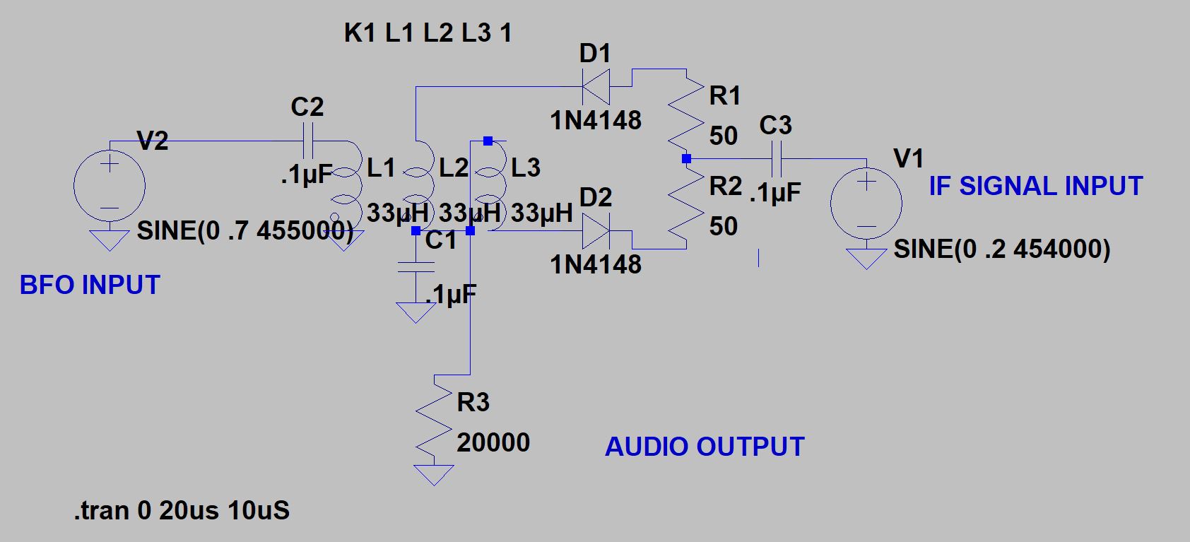
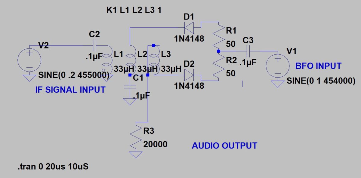
After I concluded that the BJT product detector circuit in the HA-600A was causing distorted SSB and CW reception, I tried the old DeMaw/Farhan circuit, this time in product detector mode. See above. This worked better, but I realized that this configuration was balancing out the BFO signal, and not the IF signal. My problem with the original product detector had been that IF signal was getting simultaneous envelope detection AND product detection. So I decided to just switch the inputs and put the IF signal into L1 (where it would be balanced) and the BFO into R1/R2 (the 100 ohm pot).
This seemed like it would reduce the envelope detection problem, right? I mean, L1 is the balanced input, right? But I wonder if we need to consider how the diodes were being switched in this arrangement. Instead of having both conducting and then both not conducting, in this arrangement one would be conducting during half the BFO’s cycle, while the other was not. That means that at any given moment, the two output sides of the transformer would be looking into very different loads — hardly a condition conducive to balance. But I used LTSpice to look at the audio output under the two different port arrangements. Sherwood advised looking at the output of the product detector with the BFO turned off –there should be no output with the BFO off. And indeed, putting the IF signal into L1 and the BFO into the R1/R2 pot resulted in less of the distortion causing envelope detection. The way the diodes were being switched didn’t seem to adversely affect the balancing out of the IF signal. I am not sure why this doesn’t seem to cause trouble.
There was, however, another problem with the use of this circuit in the Lafayette HA-600A: port isolation. The BFO signal was getting back into the IF signal input on L1. I could see it on the S-meter. This was worrisome not only because of the S-meter, but also because the same circuit was driving the receiver’s AGC — in effect, the BFO was turning the gain down. Theoretically, this should not have been happening. Look at the transformer. the BFO currents going through L2 and L3 should be of opposite polarities and should be cancelling each other out in L1. But obviously this was not happening. Perhaps this was the result of the sequential way the diode are switching in this arrangement. On the bench, if I put the BFO into L1, I saw very little BFO signal at the R1/R2 junction. If I put the BFO signal into the R1/R2 junction, I was a lot of BFO signal at the top of L1. And that is what I saw on my S-meter when this circuit was used in the HA-600A.
On the bench, if I turned off the BFO and put an AM modulated signal into the junction of R1/R2, I can see audio getting through once the input signal reaches 1 volt peak. I do NOT see that kind of “breakthrough” envelope detection when (with the BFO off) I put a modulated signal into L1. So the singly balanced circuit is doing that it is supposed to do — it is balancing out the the signal going into L1.
So it seemed that with the singly balanced circuit I would have to choose: suffer from the poor port isolation or AM breakthrough. Clearly it was time to go for a doubly balanced circuit. And that is what I did.
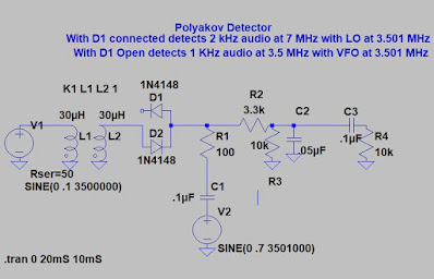
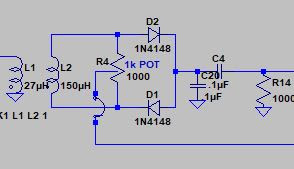
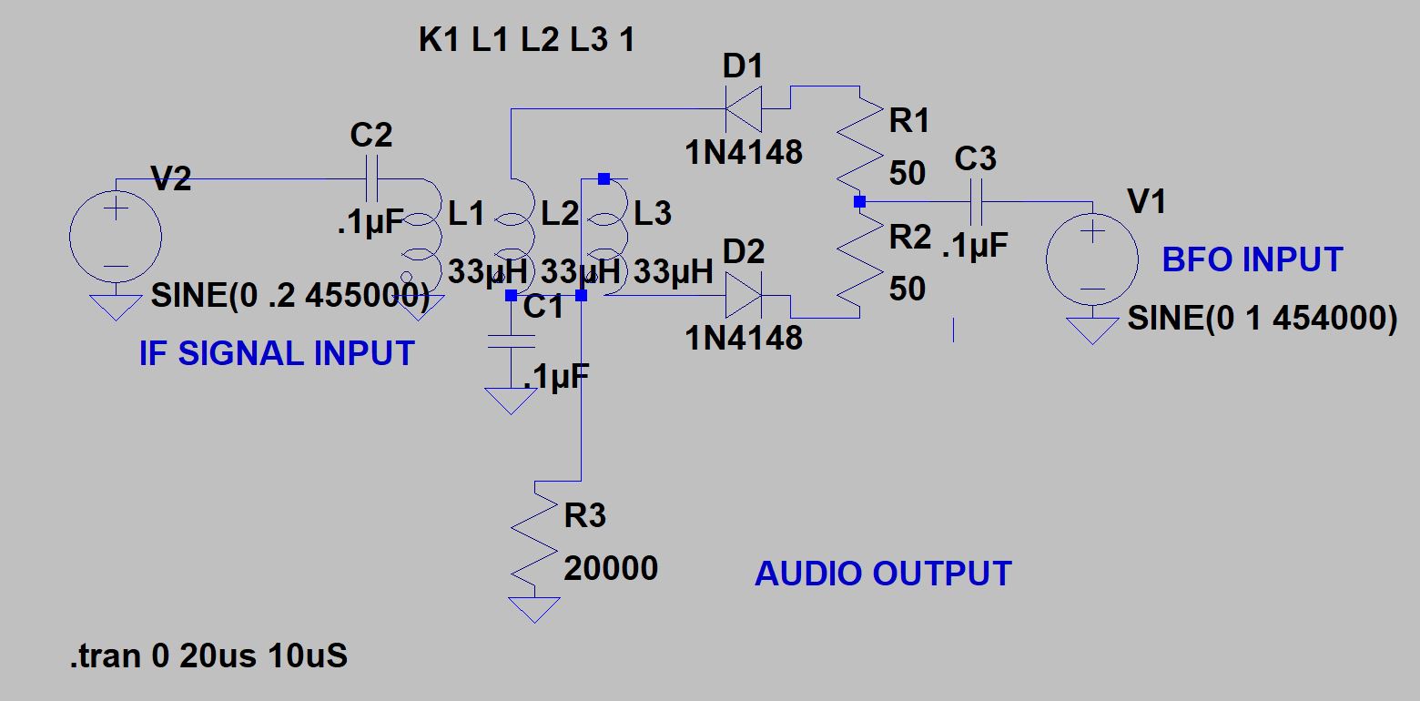
Finally, I took a look at another two diode detector, the Polyakov or “subharmonic” detector. This is a really interesting circuit that can teach us a lot about how mixers work. Here you can run the local oscillator at 1/2 the signal frequency. With two diodes back to back, the incoming signal is being sampled TWICE during each cycle of the local oscillator. That is equivalent to having the signal sampled at twice the local oscillator frequency. This circuit allows you to run the oscillator at a much lower frequency — this could allow much greater oscillator stability. In the circuit above, with both diodes connected, a 7 MHz incoming signal would produce a 2 kHz tone.
Another big plus of this circuit comes if you take D1 out of the circuit (as shown). In this configuration the circuit becomes a normal diode detector. Here it will receive a signal at 3.5 MHz, converting that signal into a 1 kHz audio tone. So you can get a direct conversion receiver for 40 and 80 meters fairly easily.
Hyderabad Field Day
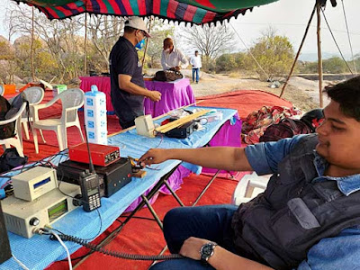
Hams in Hyderabad, India held a Field Day this week. That looks like a uBITX next to that HT. FB!
More info here:
So Many Wonderful Things on W7ZOI’s Site
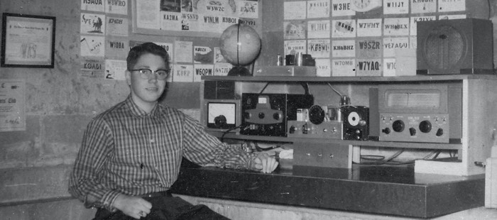
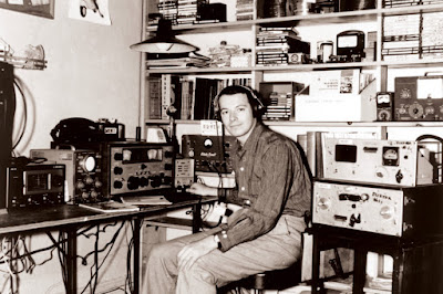
There he is. Wes Hayward, W7ZOI in 1957. I had never seen this picture before. I found it on Wes’s recently updated “shackviews” web page: http://w7zoi.net/shackviews.html .
There are so many treasures on that page, and on all the other portions of Wes’s site.
Some highlights for me:
— Wes’s description of the station in the above picture.
— On his page about Doug DeMaw, Wes mentions that after Doug edited Wes’s 1968 article about direct conversion receivers, Doug built some himself, experimenting with different product detector circuits. Having used Doug’s mixer circuit in many of my rigs, and having recently experimented with different product detectors for my HA-600A, I kind of felt like Doug was watching over my shoulder, guiding me along as I experimented.
— Wes’s use of a digital Rigol oscilloscope. Makes me feel better about giving up on my Tek 465.
— The page about Farhan’s visit to Wes, and the awesome gathering of homebrew Titans that ensued…
— Wes’s meeting with Chuck Adams.
Thanks Wes. Happy New Year and best of luck in 2021!
Diode Ring Magic
I continue to work on the product detector of my Lafayette HA-600A. This work has caused me to brush up on my understanding of how mixers really work.
I think one of the most interesting mixer circuits is the diode ring. With just four diodes and one or two transformers, this device manages to take an incoming signal and multiply it by either 1 or -1 depending on the polarity of the local oscillator signal. That is pretty amazing.
Alan Wolke W2AEW did an excellent video on this: https://www.youtube.com/watch?v=junuEwmQVQ8
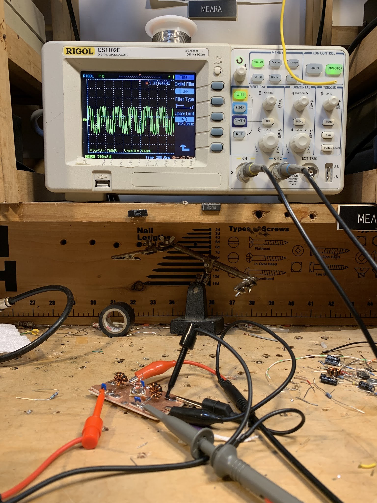
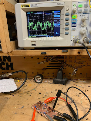
Inspired by Alan, I took my most recent homebrew diode ring mixer (with transformers from Farhan, diodes from Jim W8NSA, and a PC board base from the CNC mill of Pete N6QW) and hooked it up to two signal generators and an oscilloscope. I had the local oscillator at 10 MHz and the signal oscillator at 7 MHz. You can see my results in the pictures (above and at the end). You can see the resulting difference frequency (3 MHz) in the broad up and down pattern. And you can see the sum frequency (17 MHz) signal in the faster oscillations. All you would need is some filtering to separate them out.
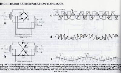
I really like the RSGB Handbook diagram (above). I think the bottom schematic with its crossed diodes really explains how the phase reversal takes place: when the LO turns on D1 and D3 (the horizontal ones), multiplication by 1 takes place. But when the LO turns on D2 and D4 (the crossed diodes), up goes to down and down to up, creating phase reversal, or, in math terms, multiplication by -1.
At a more basic level, mixing takes place whenever — in a non-linear circuit — one signal is controlling the gain or attenuation experienced by the other signal. A complex waveform results, a waveform that contains sum and difference products. A circuit like the diode ring, that alternately multiplies by 1 and -1, is non-linear in the extreme, and the multiplication is controlled by the LO. The results can be seen in the diagram’s complex waveforms, on Alan’s Tek ‘scope, and on my Rigol. And in those complex waveforms you can SEE the sum and difference frequencies. That is really cool.
Improving the Product Detector in the Lafayette HA-600A
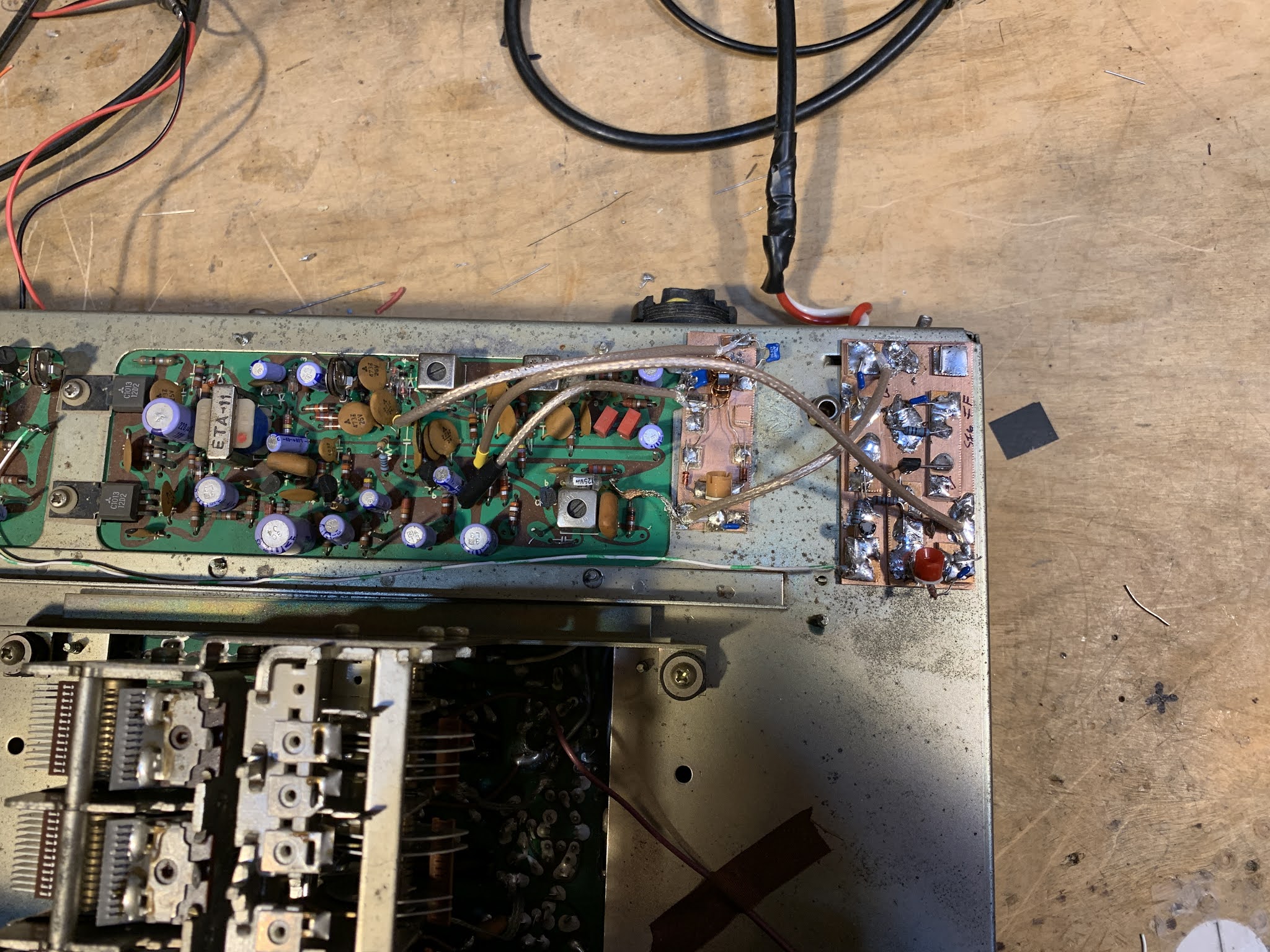
Diode product detector on the left, BFO amp in the right
As noted in an earlier blog post, I didn’t like the sound of SSB and CW when using the product detector in my Lafayette HA-600A. It just did not sound right. The receiver sounded fine on AM with the diode detector. But when I switched in the product detector, it sounded bad. The BFO was fine. The problem was there even when I used an external BFO. And SSB sounded great when I just coupled some BFO energy into the IF chain and used the diode detector to listen to SSB. My suspicions were focusing on the very simple BJT product detector.
Steve N8NM built the HA-600A product detector both in LTSpice and in the real world. It worked fine in both versions. Steve even put the product detector into his S-38 receiver — he reported it worked well there.
I too built the thing in LTSpice. Then I went and rebuilt the circuit on a piece of PC board. I connected the new circuit to the HA-600A, using my external FeelTech sig generator as the BFO. IT STILL SOUNDED BAD ON SSB.
At this point I started Googling through the literature. I found a promising article by Robert Sherwood in December 1977 issue of Ham Radio magazine entitled “Present Day Receivers — Problems and Cures.” Sherwood wrote:
“Another area that could use additional work is the product detector. As the name implies, its output should be the product of the two input signals. If BFO injection is removed, output should go to zero. If this is not the case, as in the Heath HW series, envelope detection is also occurring, which causes audio distortion.”
I checked my circuit. When I removed the BFO signal from the product detector, envelope detection continued. In fact, with the receiver in SSB mode, and with the BFO disconnected, I could listen to the music of WRMI shortwave. It seemed that Sherwood was explaining well the problem I was having: Simultaneous envelope and product detection was making SSB sound very bad in my receiver. What I was hearing just seemed to SOUND like what you’d get with a mixture of product and envelope detection: “scratchy” sounding SSB. This also seemed to explain why SSB would sound fine when using the diode detector with loosely coupled BFO energy — in that case it would be envelope detection only, with no ugly mixture of both kinds of detection.
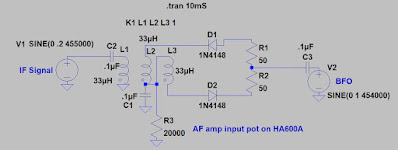
So I built a better detector. I had had great luck with the two diode one trifilar transformer singly balanced design used by both Doug DeMaw and Ashhar Farhan. I built the circuit using one of the trifilar toroids given to me by Farhan, and connected it in place of the original BJT product detector. With the FeelTech Sig Gen as BFO, I got good results — most of the signal disappeared with I disconnected the BFO. Looking at the circuit, I realized that I was balancing out not the IF signal but instead the BFO signal. To minimize envelope detection I needed to put the IF signal on the balanced input of the product detector (to L1 in the diagram above). When I did this, envelope detection seemed to disappear completely and the receiver went silent when I disconnected the BFO.
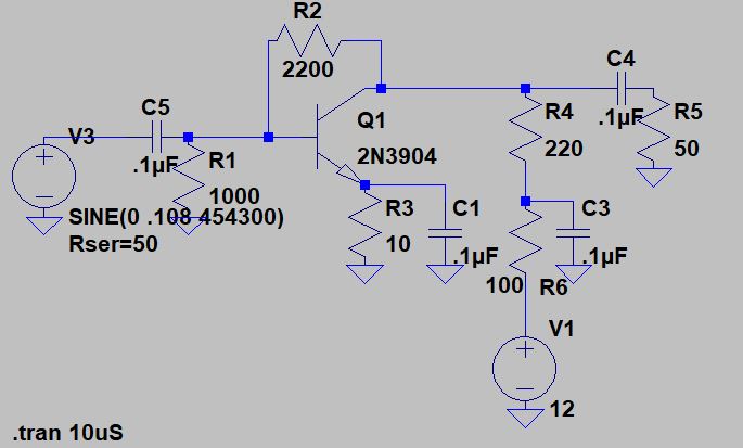
Finally, I needed to find a way to use the BFO in the HA-600A with the new product detector. Obviously I needed more BFO signal — I needed about 7 dbm, enough to turn on the diodes. I converted the outboard product detector board into a simple amplifier and put it between the HA-600A BFO and the BFO input port of the new product detector. This works fine.
A few issues remain:
1) The output from the HA-600A BFO through the above BFO amp (and across the 50 ohm resistor) is NOT a pretty 455 kc sine wave. But the peaks of the distorted wave appear to be enough to turn on the diodes, and when I look at the voltages across each diode (on my two channel ‘scope) I see mirror images — one is on when the other is off. Is this good enough?
2) Moving the BFO input from L1 to the junction of the two 50 ohm resistors (that is actually a 100 ohm pot) has big implications for how this mixer works. With the BFO energy going through the toroid, BOTH diodes are being alternately turned on and turned off. But both are on, and then BOTH are off. With the BFO energy going in through the other side, one diode turns on when the other is off. I think the mixing result is the same, with AF coming out of the output port, but the way the mixer works in this configuration is very different. Does this sound right?
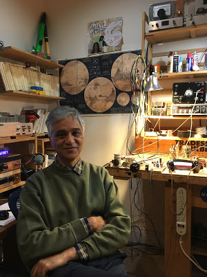
On the Cover of The Rolling Stone (Almost) — Jac Holzman, Elektra Records, and Ham Radio
Thanks to Stephen VK2BLQ for alerting us to this. That is Jac Holzman of Elektra Records fame, pictured in a recent article in Rolling Stone:
The Rolling Stone caption says he is in his “home studio,” but we recognize it clearly as a ham shack.
Here is another article about Jac:
ARRL reports that his callsign was K2VEH.
Hey, Pete plays guitar. So does Farhan. Should we have our people call Jac’s people? Maybe do lunch?
Ryan Flowers’ Admirable Approach to the BITX40 Module
We must remember that Farhan designed the BITX transceivers — and especially the BITX40 Module — in the hope that these rigs would encourage hams to tinker, to modify, to change and to repair. When I read Ryan Flowers’ blog post, I thought that Farhan’s mission has been accomplished.
https://miscdotgeek.com/bitx40-rebuild-part-1-mistakes-planning-and-teardown/
I was also struck by how nice it is that Ryan has a sentimental attachment to this BITX40 module because it was a gift from his wife. That’s the kind of thing that gives a piece of electronic circuity soul.
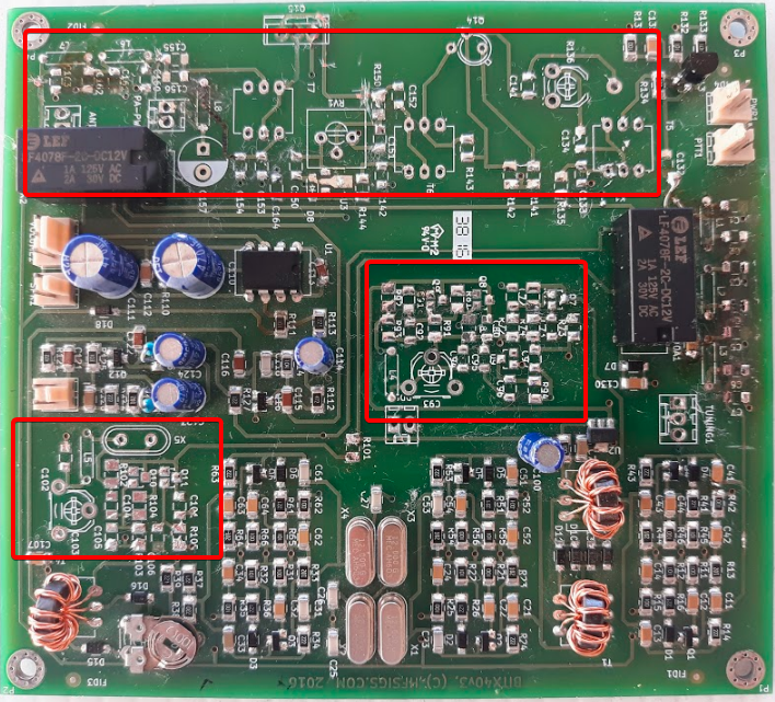
Above we see Ryan’s module with many of the parts removed in the sections that he feels he messed up. This is obviously a good approach, but it reminded me of the nightmare I’ve had (and I am not the only one) where, in frustration, I take ALL the parts off a recalcitrant board.
Stick with it Ryan! You are on the right track. And it sounds to me like you WILL soon be homebrewing from scratch your own SSB transceiver.
A while back we built a blog with many nice mods for the BITX40 Module:
Wisdom from AA0ZZ: NO LIBRARIES! ASSEMBLER CODE ONLY! — “Digital Crap” — “No Magic Fruit” What qualifies as a real rig? Si570 vs. Si5351
Bill,
Why do you guys make your Soldersmoke podcasts so darn intriguing such that I can’t listen to them in the background while I’m doing something else? Good grief! I start listening and before long you make me stop and chase down a rabbit hole to find something new that you mentioned that I had no clue was out there. Before long I’m doodling out a new sketch or playing with at a new design for something I really need to experiment with or build “next” or something I need to try. It is taking too much of my time!! J
I’ve been listening to your podcasts for years. Way back, before I knew you and before I knew you were doing these Soldersmoke blogs with Mike, KL7R, and just before he was so tragically killed, I was collaborating with him on a simple frequency counter project using a PIC microcontroller. We were making good progress on a neat design. I later completed the project but always kept his contributions noted as part of the source code.
I’ve been making PIC-based VFOs for years – dating back to about 2000 – aiming them at builders who were looking for something to go along with Rick Campbell’s (KK7B) receivers. Rick is a good friend now, after we met in the Kanga booth at Dayton where we both were demonstrating our stuff. (Bill Kelsey (N8ET) of Kanga, was the “marketer” for my kits as well as Rick’s for many years.) My original VFO kits used a DDS (high-end AD9854) that simultaneously produced I and Q signals which made it perfect for Rick’s phasing gear. Rick is a big supporter of my work but he still kids me about polluting his beautiful analog world with my “digital crap” (copyright KK7B term). When I came out with a newer version VFO using a Silicon Labs Si570 PPLL (I can hear already Pete Juliano groaning) it was a big improvement over the AD9854 in noise/spur reduction. I documented this all in a QEX article in about 2011 and Rick (and Wes Hayward) were very supportive/appreciative of my work.
I have used the Si5351 also and I understand Pete’s point of view. It’s “plenty good” for most amateur projects. However, it remains a fact that the Si570 is a better part and produces a cleaner signal. That’s the reason why the Elecraft KX3 uses a Si570. Granted, the newer Elecraft KX2 uses a Si5351 but it’s most likely because they wanted to preserve battery life (the Si570 uses more power but not nearly as much as the AD9854) and also to reduce the cost. I do understand! I also fully understand the ability of the Si5351 to produce I and Q signals via different channels. I’ve had extensive conversations about this with Hans Summers, at Dayton and online. I use a pair of Flip-Flops on the output of the Si570 instead. My PIC code driving the Si570 is ALL written in ASSEMBLER code. Yep! I’m an EE but have had a career mainly in software development and much of it was writing assembler code. I dare say there aren’t too many gluttons for punishment that do it this way. I do it because I want to understand every line of code don’t want to be dependent on anyone else’s libraries. Every line of code in my VFO’s and Signal Generators is MINE so I know I can debug it and it can’t get changed out from under me. (This problem bit Ashar Farhan hard on the Raduino of his BitX. Tuning clicks appeared because the Si5351 libraries he used changed between the time he tested it and released it. I was really appalled when I dug into this and resolved to NEVER use libraries that I didn’t write myself. Similarly, this also makes me have some distaste for Arduino sketches. I would rather see ALL of the code including the initialization code, the serial routines, etc, rather than having them hidden and get pulled in from Arduino libraries. That’s similar to the reason why Hans Summers didn’t use an Arduino in his QCX. He used the same Atmel microprocessor but developed/debugged it as “C” code with the full Atmel IDE/debugger.
By the way, Pete mentioned the Phaser FT8 transceiver by Dave, K1SWL, in a recent podcast. Dave is a very close friend, even though I haven’t met him in person since about 2000. We Email at least daily and some of it is even about radio. J I did the PIC code for the tiny PIC that controls the Si5351 in the Phaser. Yes, it’s written entirely in Assembler again! I do know how to do it for a Si5351. That Si5351 code is not nearly as much “fun”, though. I know, this will make very little difference to guys who write Arduino “C” code to control it but under the covers it’s a world of difference. It takes me about 15 serial, sequential, math operations to generate the parameters for the Si5351. None of them can be table driven and they all have to be performed sequentially. (This is all hidden in about 5 lines of complex, Arduino “C” code but the operations are all there in the compiled assembler code.) In contrast, my Si570 code is almost all table driven. I just have to do one large (48-bit) division operation at the end to generate the parameters. Yes, that’s a bit of trickery to do in ASM. There are no libraries do this.
I will point out one more advantage of the Si570 in comparison to the Si5351. It has the ability to self-calibrate via software instead of relying on an external frequency standard. In my Si570 app I can read up the exact parameters for the crystal embedded inside the Si570, run my frequency-generating algorithm “backwards” and determine the exact crystal frequency (within tolerances, of course) for that particular Si570. Then I update all the internal tables using that crystal frequency and from then on all generated frequencies are “exact”. I love this! Frequency often moves by about 6 kHz on 40M.
Oh yes, I must mention the difference of home solderability of the si570 vs the Si5351. Those little Si5351 buggers are terribly difficult to solder at home while the Si570 is a breeze. I know, many folks will just buy the AdaFruit Si5351 board and it’s already soldered on but, again, I like to do it all myself. No “magic Fruit” for me.
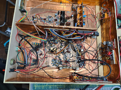
Now that I retired a couple of years ago and am getting out of the VFO kitting business I can finally build complete rigs instead of just making the next-generation VFO’s for everyone else to use. I recently build a tiny, Direct Conversion rig with a Si570 signal generator (of course) and a diode ring mixer (ADE-1). Look at my web page, www.aa0zz.com to see it, along with my VFO projects that I’ve been building in the past. As you well know, Direct Conversion is fun to build and the sound is astounding; however, they are rather a pain to use! Yes, I did make it qualify as a real rig by making several contacts all over the country. (Wes Hayward gave me the criteria: he told me that I must put any new rig on the air and make at least one contact before it qualifies as a real rig.)
The new rig that’s on my workbench is my own version of a phasing rig, experimenting with a Quadrature Sampling Detector (QSD, sometimes called a “Tayloe” mixer), using some ideas from Rick’s R2 and R2Pro receivers and many innovations of my own. At present my new higher-end Signal Generator works great, the QSD receiver works great (extremely quiet and MDS of -130 dB on 40 meters) and the transmitter is putting out about 16 watts with two RD16HHF1’s in push-pull. You can take away my “QRP-Only-Forever” badge too, not that I’ve ever subscribed to that concept! Still more tweaking to do with the TX but now I’m also working on the “glue” circuitry and the T/R switch. The SigGen, RX and TX are all on separate boards that plug into a base board which has the interconnections between boards and the jacks on the back. I’ve built DOZENS of variations of each of these boards. Fortunately they all fall within the size limit criteria to get them from China at the incredible price of $5 for 10 boards (plus $18 shipping) with about 1 week turnaround. Cost isn’t really an object at this point but it’s more of getting a hardware education that I sadly missed while I concentrated on software for so many years. it’s certainly nice to have willing mentors such as Rick, Wes, Dave (K1SWL), Don (W6JL) and many others to bounce my crazy ideas off. Yes, I’m having a ball!
I was licensed in 1964 but out of radio completely from 1975 to 1995. Do you like the picture of my DX-100 on my web page? My buddy in the 60’s had a Drake 2B and I drooled over it but couldn’t afford one.
Now I must finish this rig before you guys send me down another rabbit hole. Too many fascinating things to think about! I literally have a “priority list” on the my computer’s desktop screen. Every time I come up with a new project idea – something I really want to play with such as a Raspberry Pi, SDR, etc, I pull out the priority list and decide where it fits and what I want to slide down to accommodate it. That’s my reality check!
Take care, Bill. Thanks for taking the time to give us many inspiring thoughts and ideas.
73,
-Craig, AA0ZZ
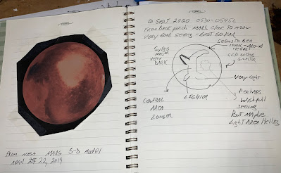
SolderSmoke Podcast #225: Mars, uSDX, G-QRP, HP8640B, DX-390, Rotary Tools, Walla Walla SDR, MAILBAG
SolderSmoke Podcast #225 is available
http://soldersmoke.com/soldersmoke225.mp3
Mars, West Coast smoke.
Pete’s Activities:
— DC receivers.
— CW offset
— GQRP talk
— The uSDX project
Bill’s Bench
— Sliding into the Vintage Test Gear Cult: HP8640B .
— Fixing up and figuring out Radio Shack DX-390 receivers.
— 220 to 110 on a few remaining devices.
— Got myself a Dremel-like rotary device.
Tech News:
— ARRL/TAPR Convention: SDR project from Walla Walla University students. Intuitive explanation for why desired and image freqs in a mixer come out with very useful phase differences.
— Chuck Adams’ Amazing Lab Notebook. Includes a simple circuit to measure resistance and Q in crystals. FB.
MAILBAG:
— Dino KL0S SITSing in his shack, homebrewing 9 MHz filters FB Dino. Airborne!
— Dave NT1U sent us the famous 1968 QST Article by W7ZOI re DC RX.
— Ron K0EIA listening to SWBC staions with uBITX.
— Ted AJ8T Korguntubes making a 12AX7 equivalent.
— Joel N6ALT sent me a nice DX-390 manual. Thanks Joel
— Bob KD8CGH alerted us to the uSDX project — story on the blog.
— Craig AA0ZZ Sent a great message with insights on computer code — I will put up on the blog.
–Tracy KN4FHX reports on optimistic prognosis for SolarCycle 25. Some chickens may have to be sacrificed.
— Stephen M0OMO Thanks SolderSmoke for rekindling interest in this hobby.
— Paul VK3HN has a cool new rig — The Prowler — check it out
— Steve N8NM working on his Sunbeam car — Pete already knew about the carburetor synch problem. N6QW knows everything.
Presence (Absence?) and Direct Conversion Receivers (with wise comments from Farhan)
Hello Bill,
I was reading an online article by Wes Hayward, W7ZO from 1968 about the history of direct conversion receivers (http://w7zoi.net/dcrx68a.pdf) . It was linked in an email in qrptech. It recounts how he had first build a dc receiver with a single diode for the detector, and how microphonic it was, and dissatisfying an experience. This was in the early days of solid state devices, and so they were hard to come by. He describes meeting another ham engineer at work Dick Bingham, W7WKR who immediately recognized that what he needed was a diode ring mixer. The story goes on to describe their experiments, and success at this design.
They decided to write up the design for QST. I won’t bore you with the details…the article is well worth reading about how Wes mailed the radio and the design to ARRL, and how it ended up in the hands of a new person on their staff there, Doug DeMaw, W1CER (later W1FB.). Here is an excerpt from the article describing Doug’s reaction to the receiver:
“This was the epiphany, the moment when Doug realized that solid-state technology had produce a new way to build a simple receiver. Doug tuned the receiver higher in the band and found some SSB. Again it was like nothing he had ever heard. It was as if the voice came from the same room. Doug used the term presence in his description.”
Here I present the earliest use, that I know of, of presence being used to describe a receiver. I have to say when I read it, I immediately thought of you guys, and decided to share.
Thanks for all you guys do.
dave /nt1u
———————————————————-
Bill replied:
Thanks Dave. Yea, that’s the 1968 article that launched the use of DC receivers. I had forgotten about DeMaw’s early use of “presence.”
Just to cause trouble, perhaps we should start commenting on “absence” i.e. “I dunno OM, I think your rig lacks a bit of absence in the mid-range… turn menu item 63b to ELEVEN!”
🙂
73 Bill
———————————————————-
Farhan wrote:
Mon, Aug 3 at 3:22 PM
When I got my license, my friend Anil SM0MFC was living in Hyderabad. He lent me his HW-8. I stringed up a 40 meter dipole with a lamp cord and worked with it. Somehow, the combination of the lamp cord length and the 40 meter inverted V made it resonate on 20 m as well. The HW-8 had a nominal antenna tuner and I worked pretty good DX.
Till date, it remains the best receiver that I have used for regular contacts. The only trouble it had was the the MC1496 was a nominal detector, it overloaded heavily with shortwave broadcast stations. There was an unnecessary RF amplifier in the front-end that they could have done without.
I made several direct conversion receivers, but never managed to hang on to any. This makes me want to build one, one of these evenings. I even have a KK7B R1 kit. but real men solder on without any PCBs or even circuit diagram!
A 7/14/21 direct conversion radio that puts out 3 watts of power is what my ideal setup would be. I am not too bothered with the images on CW. I just tune them out in my head. Real soon now, at the moment, i am trying to finish a radio that has been in the works for years. Finally, I am making some headway.
-f
———————————————
Farhan of course is no slouch in the DC receiver area. Years ago he wrote a wonderful post about building a DC receiver with his cousin for her class project:
Included in this post was a passage that I included in my book SolderSmoke — Global Adventures in Wireless Electonics:
————————–
Why build a receiver?
Why do you want to build it? These are available at the Dubai Duty Free asked Harish, an old friend, when he spotted us struggling over the DC40 one evening. I didn’t have an answer to this question and considering the amount of work piled this quarter, it appeared to be a sensible thing to ask.
I think this question is answered by us all in different ways. My personal answer would be because we human beings are fundamentally tool builders. We have an opposable thumb that allows us to grip the soldering iron.
For an engineer (by the word ‘engineer’, I don’t just mean those who have a degree, but anyone who applies technical knowledge to build things) the act of building a receiver is a fundamental proof of her competence and capability. It is much easier to put out 1 watt signal than it is to receive a 1 watt signal.
A simple definition of a good receiver is that a good receiver consistently, clearly receives only the intended signal, such a definition hides a wide range of requirements. The receiver has to be sensitive enough to pick up the weakest signal imaginable (note: clearly), it has to be selective enough to eliminate other signals (only), it has to be stable enough (consistently).
For a ham or an engineer, building a usable receiver is a personal landmark. It establishes a personal competency to be able to understand the very fundamental operation of the radio and mastery over it.
——————–
Bill: OM Ryan Flowers did a 5 part series on building the DC40. If you are want to build one, I suggest you use the schematics on Ryan’s site. There was an error in Farhan’s original schematic — Farhan corrected it but some of the incorrect schematics are still floating around the internet. Here is part one of Ryan’s series:
 |
| Farhan’s DC40 |
Paul Taylor’s Quarantine “Summit Prowler 7” and some Radio Archaeology
Paul Taylor VK3HN has really outdone himself in this video (above) and blog post. He describes coming across a somewhat mysterious homebrew SSB exciter with some cryptic markings on it. Paul eventually figures them out. We still don’t know who the builder VK3WAC was — can anyone find him in their logbooks?
As Paul goes through the description of the transceiver he built around the mystery exciter, he mentions a number of hombew heroes including Farhan VU2ESE, Peter DK7IH, Eamon EI9GQ (I have to get his book!), and Don W6JL. Also, our beloved SSDRA book plays a prominent role in the story.
Paul’s video is really beautiful — at one point the camera pans the landscape and we see kangaroos in the field. It is also refreshing — as we suffer in the heat of the northern hemisphere summer — to see Paul and his friends out on the summits in their winter coats and hats.
It looks to me as if Paul built this rig during the current emergency, so I will list it as a Quarantine rig. Every dark cloud has a silver lining, and Paul’s rig has added a bit of silver to the dark COVID cloud. Thanks Paul.
https://vk3hn.wordpress.com/2020/07/26/something-old-something-new-a-four-band-5w-50w-ssb-cw-transceiver-summit-prowler-7/
An Attenuator from Fred KC5RT
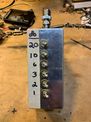
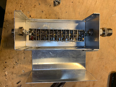
Fred, KC5RT, sent me an electronics “CARE Package” with lots of really useful stuff, including an attenuator with switches. All I had to do was find a box and some connectors. An appropriate box was quickly found in my junk box (TRGHS). So Fred’s attenuator was added to my attenuator arsenal — thanks to Farhan for getting this started.
I’ve already put Fred’s attenuator to good use: Instead of building an RF gain control for my Q-31 receiver, I just put the attenuator between the antenna and the receiver.
Thanks Fred!
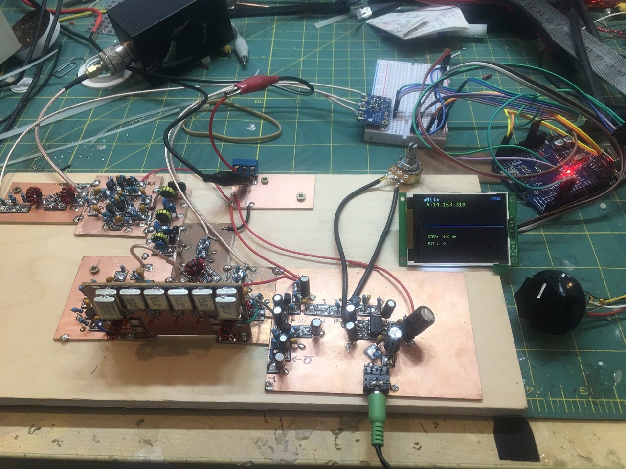
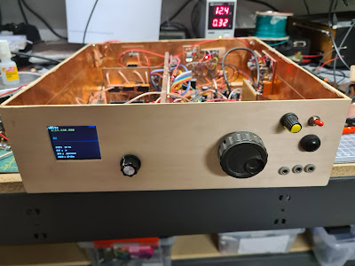
A Swedish Homebrew uBITX built in Dubai
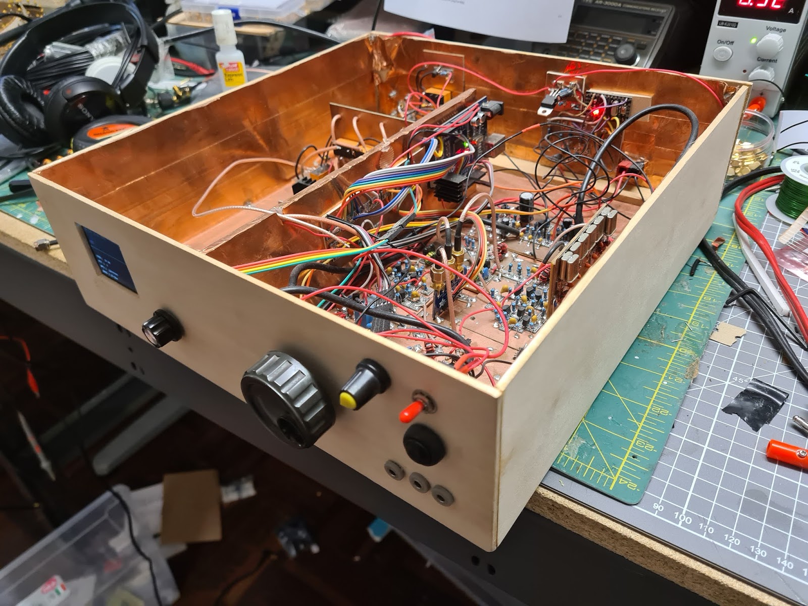
It was great to get an update from Martin. He has moved his workshop from Dubai back to Sweden. We have seen lots of homebrew BITX monobanders, but very few homebrew multiband uBITXs. Check out Martin’s. Very FB. The input from Farhan was very cool, as was Martin’s wise decision to follow Farhan’s suggestion and to pause construction once the receiver was working. As Martin put it, “I halted the build for a couple of days and just enjoyed listening.” Thanks for the update Martin.
Dear Bill and Pete,
Here comes a long overdue update from my workbench, my last update was back in March 2017 when I had completed my first transceiver project.
I did not stop building and quite soon after I completed the CW transceiver Farhan posted the first schematics of the uBitx, why not? Why not get into a multiband CW-SSB transceiver as my next project.
After completing the receive part I was amazed…
I halted the build for a couple of days and just enjoyed listening.
When it was time to start on the filters and the main RF Amp I sent Farhan an email asking about the way forward, he responded like this on May 17th 2017
“martin,
first, let me congratulate you, i suppose you are the first one to build a ubitx after me! second, i am not happy at all with the transmit line up, the drivers were not doing a good job above 14 mhz. i have replaced the 2n2219s with parallel 2n3904s. i also had to add two more LPFs, for proper harmonic suppression. i am headed for dayton today. once in dayton, i will try to find time to send you the latest circuit diagram.
once again, congratulations on a wonderfully constructed ubitx.”
Wow, what a shot in the arm for a fairly new home brewer!!! I was now back full speed with solder melting. I completed the filter bank and the RF amp, this is where I am starting to move away from the published diagram, I believe it is good to make it your own a little.
The end result was great, I worked many many stations in Europe and Asia with this little machine both SSB and CW.
In 2019 we decided to move back to Europe, the workbench and all boxes with parts and junk together with the rest of the household found their way into a 40ft container and was sent of to Sweden.
The A65DC Laboratories became SM0P Laboratories, the iron is still always hot and there is something brewing here all the time.
Thanks for a brilliant show boys,
Martin SM0P

SolderSmoke Podcast #223 Field Day, Club Talks, Patreon, NanoVNA, Farhan Video, SPRAT, BIG MAILBAG
SolderSmoke Podcast 223 is available:
27 June 2020
Quarantine Field Day!
Ironically, THIS YEAR we are both participating
Pete’s FD Plan, Bill’s FD plan
Talking to Clubs:
Pete’s talk to the Cedar Valley Iowa Club
Bill’s talk to the Vienna Wireless Society
Pete’s Bench
DDC SDR
Ideas from the Summer SPRAT
Mean Well Voltage Regulator
SHAMELESS COMMERCE DIVISION: PATREON. SS is an SV DELOS WANA-BE!
We got our very first Patreon Patron! Jonathan Magee from the UK! Upper Left on the blog.
Continue to use our site for your Amazon purchases.
Bill’s Bench
NanoVNA
Understanding L Networks
+/- 6kHz Ceramic filter for Q-31
Lobes, Nulls and WSPR
Miscellaneous:
Farhan’s feedback Amplifier Video
British Antarctic Broadcast heard (sort of)
MAILBAG:
Mauro VA6BRO liked the SolderSmoke book. Thanks Mauro
Tryg in Galway Ireland is listening. Hope to get you the signed books Tryg.
Michael N4MJR suggested that I use N2 Corona Quarantine Radio as my phonetics. I dunno…
Ed DD5LP has been helping us get SS rebroadcast on a German SW broadcast station. Stay tuned!
Rogier PA1ZZ in California sent an e-mail about the Don Lee Broadcast System. Thanks Rogier!
Rick KE3IJ Silver Skirt on his 2B also. W3GOO did it. Rick traded his Commodore 64 for the 2B. Yea!
Walter KA4KXX has a simplified circuit for the MMM! From UK
Peter VE1BZI thank us for the tribal knowledge. Dipolo Crilolo
Peter VK2EMU Wee need someone to make the Constructor Crusader badge.
Scott KA9P sent us the Amateur Wireless cover from 1934 with the Constructor Crusader thing.
John GM4OOU Built lockdown rig. we want pictures!
Jerry KI4IO His version of the Sproutie by AA7EE FB
Adam N0ZIB built a MMM
Wouter ZS1KE in South Africa — comparing notes on Drake 2-Bs
Randall KD5RC wants to get started in HB.
Feedback on Farhan’s FB Feedback Amp Video
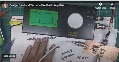
As I said a couple of days ago, Farhan has put out a very informative video on amplifier design. During the video we can see him determine bias, feedback and load levels, then select component values. We then see him actually build the amplifier “ugly style” and use his Antuino to test it. Fantastic.
Watch Farhan’s video here: https://www.vu2ese.com/index.php/2020/06/18/feedback-amplifier/
I sent Farhan some of my reactions to the video. In the hope of stimulating some discussion, I repeat them here:
___________________
Wow Farhan, I really enjoyed your video and learned a lot. You definitely have the Knack for explaining this stuff.
I have been struggling to understand feedback amps for a long time. I took up this topic on pages 187-190 of the “SolderSmoke — Global Adventures” book. I was more focused on the benefits of FB amps, and on how and why feedback affected input impedance.
I took notes as I watched:
— I liked the fulcrum analogy.
— Really wonderful how you describe the selection of components to get desired bias.
— Even better when you explain tapping down of RF coil to get 50 ohms to look like 200 ohms. Great stuff.
— Standardized on BNC. FB!
— .1uF caps. Love them! No argument here!
— I copied your resistor list. Will use it with Mouser.
— Saving the pigtails. Indeed!
— I like your ugly “resistors first” technique. I may have to move away from Manhattan.
— Wow. Ugly circuits IN SPAAAAACE! FB!
— 2N3904 I always think it is EBC when looking at the flat end of transistor with leads facing down. Only had reverse pinout with PN2N2222. EBC is my usual assumption.
— I still have the big box of trifilars you left me. I use them. Thanks!
— I like that VTVM in your Antuino. Very handy. Want one! Also, We need to get the Antuino to go down to below 455 kHz.
— I also like your dual Return Loss and SWR display. I think in terms of SWR. Return Loss sometimes messes me up.
— Didn’t know about the Hold and Zoom feature on Antuino. FB.
— Your measurement of the Q of the crystal was awesome.
— I checked my soldering iron temp: I’m at 480 C A bit too hot. Will back off.
— Good description of need for an attenuator at amp output to keep it in Antuino’s range.
— As I watched you tug on the components after the solder cooled, I remember an old and silly admonishment from the ARRL Handbook: NEVER use solder for mechanical connections. Ha! They were WRONG!
— Demonstration of the flatness of feedback was great.
— I found your measurement of impedance using the SWR feature of the Antuino to be very useful. Is there a chart relating the SWR/Return Loss to actual impedance values?
— Loved your description of how output impedance affects input impedance. That is why you advised use of TIA amps in my DIGI-TIA. But now I’m thinking that if I can accurately measure impedances of non-TIA amps, I can design L networks that will keep the crystal filter passbands ripple-free, right?
— Great explanation of the benefits of the 6 db pads at amp output. Allison often recommends this. Now I know why.
— Wow! Now I KNOW what that two-tone box you left with me is for! Now I understand how it can be used to measure IMD on FB amps. I pulled mine out just as you began to discuss yours. Really cool.
Thanks a lot Farhan for doing this. These videos will be of long-lasting use to homebrewers around the world. I hope we will see many more VU2ESE videos like this one.
73 Bill
Excellent Video from Farhan on Amplifier Design
Farhan has produced a really excellent video explaining the theory behind the feedback amplifiers that we use in so many of our circuits. He takes us through the design and construction of these amplifiers, then uses his Antuino network analyzer to test an amplifier and to measure input and output impedances.
There is a lot of tribal knowledge and wisdom in this video!
Check it out here:
https://www.vu2ese.com/index.php/2020/06/18/feedback-amplifier/
Thanks Farhan!