Farhan’s New Design: A General Coverage Transceiver: The Minima!

The homebrew phone QRP community has been waiting anxiously for the unveiling of Farhan’s new design: The Minima. It is a general coverage transceiver with many innovative circuit features. It has an Arduino in it and an Si570. Farhan’s write up of the design process and the construction of the prototypes is really interesting.

http://www.phonestack.com/farhan/minima.html

I’ve built FOUR JBOTs and TWO BITXs. I even built Farhan’s Subway Sandwich Straw signal generator. So even though I’ve been trying to keep my rigs all discrete, I know I will build this one too.

Three cheers for Ashhar Farhan! Viva La Minima!

Our book: “SolderSmoke — Global Adventures in Wireless Electronics” http://soldersmoke.com/book.htm Our coffee mugs, T-Shirts, bumper stickers: http://www.cafepress.com/SolderSmoke Our Book Store: http://astore.amazon.com/contracross-20

BITX 2040 Build Update #3 Receiver Sounds Great!

There it is, my second BITX transceiver, this one for 20 and 40. Once I got the VFO sorted out, this one went together very quickly. Obviously experienced gained on the first project was a big help.

I followed Farhan’s advice and characterized the 11 MHz crystals in the filter. Then I used the AADE filter design software to build a 3 KHz filter. Using my Arduino DDS signal generator and the new Rigol ‘scope, I was able to do a manual sweep across the passband — it looked very close to what was predicted by the software.

This morning I built the bandpass filter for 20. As soon as that was done, I fired up the receiver. This was an amazing experience for me: a homebrew receiver that worked right away! That never happened before. I’m listening to 20 meters now. It sounds great. I even managed to demodulate and display some SSTV. The VFO seems very stable.

I still have to build the RF amplifier stages, the bandpass filter for 40 and low pass filters for 20 and 40 (I know Steve Smith is watching!). Then it will be time for cabinetry. I guess I should put some paint or varnish on that walnut box. Any recommendations? I’ll line it (on the inside) with copper flashing material.

Our book: “SolderSmoke — Global Adventures in Wireless Electronics” http://soldersmoke.com/book.htm Our coffee mugs, T-Shirts, bumper stickers: http://www.cafepress.com/SolderSmoke Our Book Store: http://astore.amazon.com/contracross-20

11 MHz IF for new BITX 20/40 Dual Bander? Also: Cabinetry and Socketry

I am gathering parts and ideas for a BITX dual bander (20 and 40 meters). I know Farhan used a 10 MHz filter for his “Simple SSB Transceiver.” But I was thinking of going a bit higher, to 11 MHz. This would allow me to run the VFO from 3.175 to 3.355 for 20 meters, and 3.695 to 3.875 for 40 meters. I’m hoping that I can do this with one single VFO (Farhan used two VFOs), perhaps with a reed relay switching in some additional capacitance for the other band. I’ll also follow Farhan’s lead and switch the Low-Pass and Band-Pass filters with DPDT relays.

I set up a simple spread sheet and looked at the VFO harmonics to see if any fell within the desired tuning ranges. That looks OK. I have not looked at mixing products between VFO and BFO. What do you folks think? Would the 11 MHz IF for these bands work? Or are there evil birdies lurking in my future?

I’ve gone ahead and bought another wood box for the new rig (I didn’t even have to suffer through a second visit to the crafts store — they are available on Amazon). I also got a roll of copper sheeting at Home Depot. This time I will prepare the box first, lining the inside with copper and preparing all the “socketry” (George Dobbs’ word) before putting the PC board in.

Our book: “SolderSmoke — Global Adventures in Wireless Electronics” http://soldersmoke.com/book.htm Our coffee mugs, T-Shirts, bumper stickers: http://www.cafepress.com/SolderSmoke Our Book Store: http://astore.amazon.com/contracross-20

Words of Wisdom (on Amplifier Stability)

From “A Simple SSB Transceiver” by Ashhar Farhan:

“What if your transmitter is unstable? Don’t curse your fate. All transmitters start out as unstable beasts. Relax.” Farhan goes on to provide some good pointers on how to tame the beast.

I’ve had very good luck with the PA in the BITX — very little cursing of fate on this project.

Our book: “SolderSmoke — Global Adventures in Wireless Electronics” http://soldersmoke.com/book.htm Our coffee mugs, T-Shirts, bumper stickers: http://www.cafepress.com/SolderSmoke Our Book Store: http://astore.amazon.com/contracross-20

SolderSmoke Podcast #155 BITX17, TEK465

Podcast # 155 is available for download (or you can listen by clicking on the button above):
http://soldersmoke.com/soldersmoke155.mp3

October 14, 2013 (Delayed Back-to-School edition)

Topics covered:

— BITX Beauty — Building a BITX17

— VFO woes, and the wisdom of Doug DeMaw’s love for crystals

— Why does a 55 year old man NEED clear nail polish varnish?

— How the VFO KILLED the Tek 465

— Trying to fix the Tek 465 (not for the faint of heart)

— New products: Justin Beiber Duct Tape, bifocal safety glasses,
magnetic reading glasses, Ward Silver’s new book

— Backwards British Bike Brakes

— MAILBAG

Our book: “SolderSmoke — Global Adventures in Wireless Electronics” http://soldersmoke.com/book.htm Our coffee mugs, T-Shirts, bumper stickers: http://www.cafepress.com/SolderSmoke Our Book Store: http://astore.amazon.com/contracross-20

BITX BUILD UPDATE #13 — VIDEO TOUR

I hope to get the next podcast out within a week or so. The BITX has been keeping me busy!

Our book: “SolderSmoke — Global Adventures in Wireless Electronics” http://soldersmoke.com/book.htm Our coffee mugs, T-Shirts, bumper stickers: http://www.cafepress.com/SolderSmoke Our Book Store: http://astore.amazon.com/contracross-20

BITX Build Update #11 — Peakin’ and Tweakin’

Oh how I love the sound of a newly built receiver! I’m sitting here listening to G0MJS on 17 meters. Lots of other stations from across the pond coming in very nicely.

Earlier in the week I had some sensitivity problems. I could hear the noise floor, but just barely. And the receiver just seemed to have trouble inhaling. So I started poking around. It seemed that each poke improved things a bit. I had used Farhan’s original schematic (mostly). Later versions put an additional transistor in the IF amp. So I went ahead and added that mod. That helped a bit. Then I noticed that BFO energy was getting into the AF amp. So I put a .1uF cap to ground at the input to the AF preamp. That took care of the RF and did no damage to the AF.

But the rig still seemed a bit hard of hearing. This morning Farhan advised me to take a look at the mixers. I used some junk-box diodes that I didn’t know too much about… I measured the forward resistance and found it to be quite a bit higher than the usual 1N914s. So I switched all 6 mixer diodes. That helped noticeably.

I also checked the input bandpass filter. It seems OK. In the process I learned to use the EMRFD filter programs (thanks Wes) and the ELSIE filter program (also very nice).

Anyway, the rig sounds great now. On to the transmitter.

Farhan advises building the power amplifier on a separate copper clad board. But I have room for it on my main board. Should I live dangerously?

Our book: “SolderSmoke — Global Adventures in Wireless Electronics” http://soldersmoke.com/book.htm Our coffee mugs, T-Shirts, bumper stickers: http://www.cafepress.com/SolderSmoke Our Book Store: http://astore.amazon.com/contracross-20

BITX Build: Update #2

Not much progress to report. But I have been thinking about the filter frequency. Here is my latest idea:

Maybe I’ll build the VFO in the 5 MHz range. This would allow me to use the 9 MHz Yaesu filter (and associated crystals) that Steve Smith sent to me (see above). With this I could be on 75 and 20 meters.

I could build another filter at 13 MHz and, using the same VFO in the 5 Mhz range, get on our beloved 17 meter band. I kind of like the idea of plug-in filters.

You can see my ideas for the board layout. I’m thinking of a Doug DeMaw Universal Hartley VFO inside the box shown above. The tuning cap you see is out of an old Heath QF-1 Q Multiplier. It has a very nice reduction drive built into the tuning shaft. It measures 19 to 148 pf.
Our book: “SolderSmoke — Global Adventures in Wireless Electronics” http://soldersmoke.com/book.htm Our coffee mugs, T-Shirts, bumper stickers: http://www.cafepress.com/SolderSmoke Our Book Store: http://astore.amazon.com/contracross-20

Building the BITX! Update #1

There it is guys: A blank canvas of copper-clad board. A clean slate ready to be filled with the components for a BITX transceiver. As you can see, I am fighting my “build first, design/plan later” tendencies. No real design work for me on this one (thanks Farhan!) but I am trying to plan where everything will go on the board. (Thanks to Jim, W8NSA for the board.) I’m going to build it Manhattan style (perhaps with an ugly dead bug or two). I’m starting with a big board because I always seemed to end up with a shortage of space. It looks like I can easily get all of the circuit (minus the PA) on this board. I’ll build the PA on a separate piece of copper-clad.

I’d like to build it for 17 meters, but if I stick with the 10 MHz filter that means I have to build a VFO at around 8.1 MHz. That’s not impossible, but in my experience it is easier to build simple, stable VFOs at lower frequencies.

I notice that there are a lot of cheap crystals available at higher frequencies. So, instead of keeping the filter at 10 MHz and trying to get the VFO stable at 8.1, what do you guys think about keeping the VFO in the 4 MHz range and building the filter with crystals in the 14 MHz range?

Our book: “SolderSmoke — Global Adventures in Wireless Electronics” http://soldersmoke.com/book.htm Our coffee mugs, T-Shirts, bumper stickers: http://www.cafepress.com/SolderSmoke Our Book Store: http://astore.amazon.com/contracross-20

HB-101 ? BITX-101?

OK, so I’ve been wanting to build a BITX-20 for a long time. Then Steve “Snort Rosin” Smith sent me a nice 9 MHz filter, and I started to think about using it to build a BITX 75/20. But I don’t really like 75 meters too much… And I have this Heathkit HW-101. I like it very much, but these rigs do not age well: Too much heat, too many cheap components, tubes on PC boards… yuck. I got tired of fixing it. I’ve occasionally fantasized about scrapping most of the HW-101 circuitry and turning this rig into a 100 watt linear amplifier. But I didn’t have the heart to do this. Then, on the way to work yesterday it hit me: Why not take the beautiful bi-directional circuitry of Farhan’s BITX design and use that to solid state most of the HW-101? Obviously I’d retain the finals and maybe the driver, and the CW and SSB filters. The VFO could be transistorized. Maybe I’d retain the tube AF amp. I’d like to add 17 meter capability. Pete Juliano took an HW-101 and added a digital dial (that’s his rig in the picture).
What do you guys think? Am I nuts? Or would this be a worthwhile project?

Our book: “SolderSmoke — Global Adventures in Wireless Electronics” http://soldersmoke.com/book.htm Our coffee mugs, T-Shirts, bumper stickers: http://www.cafepress.com/SolderSmoke Our Book Store: http://astore.amazon.com/contracross-20

Ham Radio, the tsunami, HW-101, Tek 465, BITX-20

I know many of you guys have seen this before. And I know that Farhan is tired of seeing it pop up again and again. But it just appeared on my Facebook page today and I watched the whole thing and saw things I hadn’t noticed before: There’s a Heathkit HW-101 (or maybe its an HW-100). There is a Tech 465 oscilloscope. There is a BTX-20!

Our book: “SolderSmoke — Global Adventures in Wireless Electronics” http://soldersmoke.com/book.htm Our coffee mugs, T-Shirts, bumper stickers: http://www.cafepress.com/SolderSmoke Our Book Store: http://astore.amazon.com/contracross-20

Peter Parker’s Knobless Wonder Minimalist SSB Rig

Oh man, Peter Parker has done it again! As he did with the Beach 40, he has come up with a circuit that will attract a lot of attention. It is a single frequency SSB transceiver with no knobs (or windows, or menus!)

Peter Marks recently had breakfast in Melbourne with VK3YE:
http://blog.marxy.org/2013/05/melbourne-meetup-with-homebrew-legend.html
There are some great pictures of the new rig, and the Beach 40.

Here’s the message from VK3YE (to the Minimalist Radio Group) that may
someday be seen as the start of the Knobless Revolution:

Some might reckon that SSB is inevitably too complex to be in the minimalist
class, but I beg to disagree.

I reckon you could build a whole SSB transceiver in 2 days of solid work. I
took a day to build what will be described below up to the stage where it

was receiving & producing a low level SSB on Tx.

Take this recipe:

1. Build the back end of the BitX http://www.phonestack.com/farhan/bitx.html
That is everything to the right of (and including) the Q2 & Q12 stages.

2. Use cheaply available 7.159 MHz crystals in the crystal filter and
carrier oscillator. Keep filter capacitor values the same. Remove L3 in the
carrier oscillator circuit. Use a slightly bigger trimmer in the carrier
oscillator (say up to 50 pF) and wire in series with crystal. Align trimmer
so carrier freq is 7160 kHz.

3. Build a power amplifier stage / relay / LPF as per the Beach 40. Just
the last 2 stages (using BD139s) should be enough. Output maybe 2w.

The result is a 10 transistor / 1 IC SSB transceiver on 7160 kHz. It’s
crystal controlled but at least during the day 2 watts to a good antenna
should be enough for people to hear and reply to your CQ calls up to 800 –
1000 km away. Of course you could go a bit more minimalist and remove the
LM386, substituting 1 transistor instead (as per the original Beach 40)
which is what I did.

The main thing that’s odd is it has no knobs – no tuning, RIT, volume, RF
gain etc. Just sockets – for mic, phones, antenna and power to feed it what
it needs (Rx RF, Tx audio, DC power) and give what you want (Rx audio and Tx
RF).

It is philosophically different to using any other transceiver. You either
accept what the radio dishes up (frequency, AF gain, mic gain etc) or you
don’t. On or off – there is no other state. Take it or leave it. Like a
cat this is a radio that lives on its own terms.

Those used to fiddling with adjustments will find the ‘knobless wonder’
transceiver causes them to be at a loose end. Those so afflicted will smoke
more, bite their nails more or eat junk food more. Sometimes elegant
simplicity in radio can be a health hazard – maybe knobless rigs should
carry health warnings.

On the other hand, and in my view this outweighs the above, there is the
aesthetic satisfaction that comes from using a rig that cannot be made any
simpler. Especially if it’s a mode, like SSB, that’s widely thought
constructionally complex. Plus it takes little in return – the power
consumption will be a fraction of what a commercial rig will demand.

73, Peter VK3YE
Our book: “SolderSmoke — Global Adventures in Wireless Electronics” http://soldersmoke.com/book.htm Our coffee mugs, T-Shirts, bumper stickers: http://www.cafepress.com/SolderSmoke Our Book Store: http://astore.amazon.com/contracross-20

Swamping or Q-Killing

Sounds like some new TV series on the Discover Channel, doesn’t it? Actually it refers to efforts to stabilize oscillators by reducing the Q of components that may be helping to turn the amplifier into an oscillator. A 300 ohm resistor across the primary of the output transformer on my most recent version of the JBOT amplifier recently solved my instability problem. As part of an effort to understand how and why I came across a CQ magazine article by Doug DeMaw. The relevant passage appears above.

Our book: “SolderSmoke — Global Adventures in Wireless Electronics” http://soldersmoke.com/book.htm Our coffee mugs, T-Shirts, bumper stickers: http://www.cafepress.com/SolderSmoke Our Book Store: http://astore.amazon.com/contracross-20

SolderSmoke Podcast #148

SolderSmoke Podcast #148 is available:
http://soldersmoke.com/soldersmoke148.mp3
December 30, 2012

SPONSORED BY usedradiomall.com

— Hurricane Follow-up
— Subliminal Mind Control to Encourage Homebrewing (beep-beep)
— The Shortcomings of the All American Five Receiver
— Solid-Stating a Heath SG-6 (with Farhan’s circuit)
— VK3YE’s Beach DSB Rig
— Tek ‘scope connection to frequency counter
— Mod to W7ZOI/W7PUA power meter
— JBOTing my 20 meter DSB Rig — A Tale of Woe
— LU1AR “The Most Interesting Ham in the World”
— Billy’s Raspberry Pi
— Latest QST, SPRAT, Hot Iron
— Videos: Landfillharmonica, Knack in Sierra Leone
— Santa delivered a Soldering Station
— MAILBAG

Our book: “SolderSmoke — Global Adventures in Wireless Electronics” http://soldersmoke.com/book.htm Our coffee mugs, T-Shirts, bumper stickers: http://www.cafepress.com/SolderSmoke Our Book Store: http://astore.amazon.com/contracross-20

A Promising Start for the SG-6 Solid State Conversion

We have kind of half a holiday today — I have the day off, but the kids went to school. I made use of the additional shack time to test the feasibility Farhan-izing my old, not-so-beloved Heathkit SG-6 signal generator. I did a quick Manhattan build of the oscillator section from Farhan’s sig generator (link in yesterday’s post). Using an idea from an old 73 Magazine article on a similar project (thanks Clint!), I smashed the tube (appropriate, don’t you think?) and connected (using the glass stump!) Farhan’s oscillator directly to the pins that lead to the switchable coils and the variable cap of the SG-6. I just wanted to see if it would oscillate, and see if there was a big change in SG-6 dial calibration.

Wow, it worked great! It oscillates very nicely on all but the upper frequency band setting (20-50 MHz). I feel confident that I’ll get it to oscillate at least up to 30 MHz. Next I’ll build Farhan’s buffer and amplifier stages. The SG-6 had a switchable attenuator — I want to include that feature in the solid state version. I’ll have to give some thought to the audio modulation feature (nice for aligning AM receivers).

Our book: “SolderSmoke — Global Adventures in Wireless Electronics” http://soldersmoke.com/book.htm Our coffee mugs, T-Shirts, bumper stickers: http://www.cafepress.com/SolderSmoke Our Book Store: http://astore.amazon.com/contracross-20

Solid State Conversion for a Heath SG-6 Signal Generator?

I’ve recently become acutely aware of the shortcomings of my signal generator.
It is a Heathkit SG-6. It is really old. It has a selenium rectifier in it. It has one of those old mic connectors on it for the output. The output is very low. But I like the cabinet and there is a nice switchable coil/variable capacitor LC circuit in there (see above).

In 2008 in Hyderabad, India Farhan went to McDonalds with his kids and went home with some straws. Soon the straws are chopped up and turned into coil forms for a signal source: http://www.phonestack.com/farhan/siggen.html

So here is my idea: de-tube the SG-6. Turn the selenium over to the HAZMAT authorities. Save the coils and the cap and most of what George Dobbs would call “the socketry.” Use an MPF-102 for the oscillator, then make use of the buffer and feedback amp from Farhan’s soda straw circuit.

What do you guys think?

Our book: “SolderSmoke — Global Adventures in Wireless Electronics” http://soldersmoke.com/book.htm Our coffee mugs, T-Shirts, bumper stickers: http://www.cafepress.com/SolderSmoke Our Book Store: http://astore.amazon.com/contracross-20

How to Get Ready to Build a BITX-20

Continuing with our workshop inspiration theme, I spotted this in the BITX-20 mailing list this morning. The response is from Farhan:

blake,

i would suggest a different route. a long and winding one, that will
finally lead to a bitx.

the idea is to learn. you do this by understanding what you build and
building what you understand. by ‘understand’, i specifically mean, being
able to measure. here is what i suggest, buy yourself a bunch of 2N3904s
from the local radio shack and some resistors and caps. then build this :

http://www.phonestack.com/farhan/testosc.gif

this is an oscillator. if you plug a coil between the open ends, it will
become a vfo, if u plug a crystal, it becomes a crystal oscillator. you can
use your frequency oscillator to check the frequency it is oscillating at,
etc.

with this, you would have mastered the first of the three blocks that make
up almost every radio circuit. but next, you must make another test
instrument. a power meter. most of us ham start out with a simple RF probe.
while that was fine and dandy for its day, now we can do much much better.
we can make a very accurate power meter that enable you to measure things
as finely as anybody in this business. W7ZOI has designed a super simple
power meter. it is available as a kit.
read about the power meter here :
http://www.kangaus.com/Documentation%20files/Power%20Meter%20Documentation%20May%202011.pdf
you can purchase the kit at www.kangaus.com
(I have no business interest with kanga or any other kit manufacturer)

with the power meter in place, you can now measure the power levels coming
out of any circuit with great accuracy.

now, you can build a single stage feedback amplifer (there are six of them
used in the bitx) on a copper clad board. using the test oscillator as an
input, you can measure how much gain the amplifer has (measure the
oscillator output, then connect the oscillator to the amp and ,measure the
amp output. the, amp output – oscillator output = amp gain).

of course, while building both these blocks, you will discover what
voltages to expect at which junction of components in both these blocks.

next, you can build a step attenuator. which is a really simple thing and
of immense value in the home lab. here is a design
http://www.arrl.org/files/file/Technology/tis/info/pdf/9506033.pdf
or you can now buy it in a kit form from
http://www.qrpkits.com/attenuator.html

finally, you can build a simple signal generator like this :
http://www.phonestack.com/farhan/siggen.html . this will allow you change
frequencies and measure what a circuit does at different frequencies. you
can use this to test how the filters are doing and get them to ‘spot’ where
you want them to.

so, there it is, a signal generator, a power meter, step attenuator, test
oscillator. four, very simple test instruments that you can build
yourself. they will give you one helluva education in radio. and within
weeks, you will understand and start building on your own!!

– farhan


> Quoting bfabman :
>
> Hello Everyone, I have been watching the group for a few months now
> with interest. I have no electronic experience to speak of, but I have
> a burning desire to make one of these, and I am wondering what all of
> you think of someone like myself building one as my first real radio
> project, to be used for qrp mountain topping. I don’t have any
> electronic test equipment for the final alignment, other than a
> standard DIG vom meter. (I am willing to buy some equipment if
> necessary) I think that this would be an awesome winter project just
> don’t know if it would be over my head. If I got it all built, could I
> actually get it aligned and working properly. I did make a Norcal
> frequency counter project last year and it turned out very well. Thanks
> for your opinions before I spend the money. Blake
>
> Paul Daulton K5WMS
> beacon WMS 185.302 khz qrss30/slow 24/7
> Jacksonville,Ar 72076
> em34wu

Our book: “SolderSmoke — Global Adventures in Wireless Electronics” http://soldersmoke.com/book.htm Our coffee mugs, T-Shirts, bumper stickers: http://www.cafepress.com/SolderSmoke Our Book Store: http://astore.amazon.com/contracross-20

SSB Generation: Ideas from Around the World


I liked this thread on the EMRFD mailing list. The question of how best to generate SSB is very interesting, and I also liked the global scope of the Q&A: Peter in Hungary asks the question, Farhan in India and Allison in the U.S. respond.

On 9/25/12, ha5rxz wrote:
When generating an SSB signal from audio and a 9 MHz carrier which would be
the best mixer to use?
a) A high-level ring bridge mixer such as the SRA-1H
b) An H-Mode mixer using an FST3125 chip
c) An H-Mode mixer using a 74HC4016
d) Something else
Note that this mixer will not be used to demodulate.
Peter HA5RXZ

……………………………..
Ashhar Farhan wrote:
In my experience, if you keep the audio level low enough, it is
difficult to beat a simple two diode mixer.with a 10 db attenuator in
the output. Having just two diodes makes balancing of reactive as well
as resistive differences of the two diodes quite trivial. Schottky
diodes are best.
One thing, I did discover though is that the balance should be to
minimize the harmonic distortion, rather than just the carrier
suppression.
What we are shooting for is to keep the In-band IMD down. Carrier
suppression is just hygiene. So, you will want to tune in to the
signal, modulating it with two tones and see it on a audio spectrum
analyzer (freely downloadable from the net) and try getting the third
spike down.
Though the ‘packaged’ mixers don’t give you the needed control for
hi-fidelity, for trivial usage, NE602 is pretty good. Just drop it
into the rig and live with what you get (which is not bad at all).
The best resource is the chapter on phasing receivers and transmitters
in emrfd. Rick is the guru. I hope he joins this thread.

– Farhan

……………………………………..
FROM KB1GMX:

I’ll weigh in..

Yes, they all work. You need a provision for adjusting carrier balance on some but anything over 40db will be good.

I’ve used 602/612s, SBL-1, SBL-1H, diode rings, and even varicap
diodes (there is a design using them in capacitively balanced
a modulator from many years ago. They all work if the levels are correct.

These days I use the sa612 for simple designs, SBL-1 with a 50ohm
pot added for balance for better radios and the 4 diode ring I’ve
used many times as its uncritical, needs only one untapped
transformer and easy to make. Most of those are listed in the
older 1975 through current handbooks and EMDRFD.

If needed I can post to the files section a few designs but
they are all textbook and all are capable of good results.
In just about all the diode modulator cases a fairly strong
carrier (5mW or more) is needed and the audio will be about
10db lower for very good result. The active devices like the
ca3028(and friends), SA612, MC1496 the levels for the carrier
and audio must be matched accordingly for the device. You can
look at the output with a scope and get a first order eyeball
call on quality (no carrier and no clipping or limiting) and a
receiver (any your ears) will tell you if its right.

Allison

Our book: “SolderSmoke — Global Adventures in Wireless Electronics” http://soldersmoke.com/book.htm Our coffee mugs, T-Shirts, bumper stickers: http://www.cafepress.com/SolderSmoke Our Book Store: http://astore.amazon.com/contracross-20

Club 465

I mentioned on the podcast that a generous friend sent me a Tektronix 465 scope. It now seems like every day I’m discovering new and interesting things about this magnificent piece of gear. I’ve also discovered that there a LOT of guys out there who are loyal and enthusiastic users of Tek 465s. George Heron, N2APB, and Joe Everhart, N2CX, have been putting out an excellent podcast called “Chat with the Deigners.” They recently talked about oscilloscopes with our friend Alan Wolke, W2AEW: http://www.njqrp.org/teamspeak/Apr10.html
George mentioned that he has a 465. Our friend Farhan, VU2ESE, is using one. Who else is in Club 465? Send us your names!


Preston. WJ2V, up in the Big Apple sent me a very interesting message about a feature of the ‘scope that I was unaware of. Thanks Preston!

Bill,


I am caught up and just listened to number 142. The podcasts continue to be new and interesting each issue. I too have a 465 workhorse in the shack. I have one suggestion that will turn it into an even more valuable instrument. Note that you have an amplified output in the back with the vertical signal presented at a BNC connector. This is made for connection to a frequency counter. In fact, some of the military versions of this scope came with a frequency counter. If you have a counter in the shack, just connect it to the vertical output in back of the scope. This will faithfully report the frequency of any wave you see on the screen. Since the signal is amplified, the counter will be able to read small signals in receiver stages, while you view them on the scope. Amazingly helpful in setting up and troubleshooting receivers. I leave a dedicated counter connected to the 465 all the time, as it enhances the usefulness of the scope many times. I also am lucky enough to have an early Steve Weber (“Melt Solder”) SASA II device available for connection to the scope whenever needed. This is a 100 MHz spectrum analyzer adapter, with a built-in calibrator. It gives a great view of the output of transmitters. But, of course, you can see the quality of a clean sine wave with just the scope. The SASA II will just help you to see where in the spectrum the junk is coming from. Sadly, I don’t think Steve made more than about a hundred of these terrific kits. Also, it did not have provision for a tracking generator, which would have made it an ideal instrument for designing and checking IF filters. Steve and I talked about this, and he said he might revisit this someday.

As to seeing your QRP (or even higher) signals on the scope, of course you would not connect a transmitter to the input of the scope–that would burn it out in short order. But a proper bypass/attenuator connected to a proper 50 ohm pass-through termination at the input to the scope would give the ability to see why your SWR meter is showing an abnormally high SWR with your homebrew transmitter that’s generating spurious stuff. There is a very practical article for building the two pieces you need on simple PC board “cabinets” (more like half-cabinets) in the wonderful Drew Diamond books, I think in volume II. These simple devices will give you the ability to see what you’re doing with your transmitters, using the scope–

72,

WJ2V

Our book: “SolderSmoke — Global Adventures in Wireless Electronics” http://soldersmoke.com/book.htm Our coffee mugs, T-Shirts, bumper stickers: http://www.cafepress.com/SolderSmoke Our Book Store: http://astore.amazon.com/contracross-20

JBOT Thoughts

Posted today to the BITX-20 Group:

Good to see so many JBOTs under construction. I recently built two of them. Farhan has asked me to share with the group my experiences using -43 core toroids. Ironically, TV cores are a bit harder to find here, so I had to go with the fancier toroids!

In my first amp (used in a 17 meter DSB rig) I used the smaller FT-37-43 cores in all three transformers. T1 and T2 were wound and placed in the same way that Farhan did with the TV cores. For T3 I used superglue to stack 4 of the cores 2×2, then wrapped them with a bit of electrical tape. I wound T3 so the input wires were on one side and the output on the other. (On this amp, I had started out using some large binocular cores from the junk box, but I had a tough time getting the amp stable with these cores, possibly because using them resulted in longer lead lengths. So I went back to the smaller FT-37-43 cores).

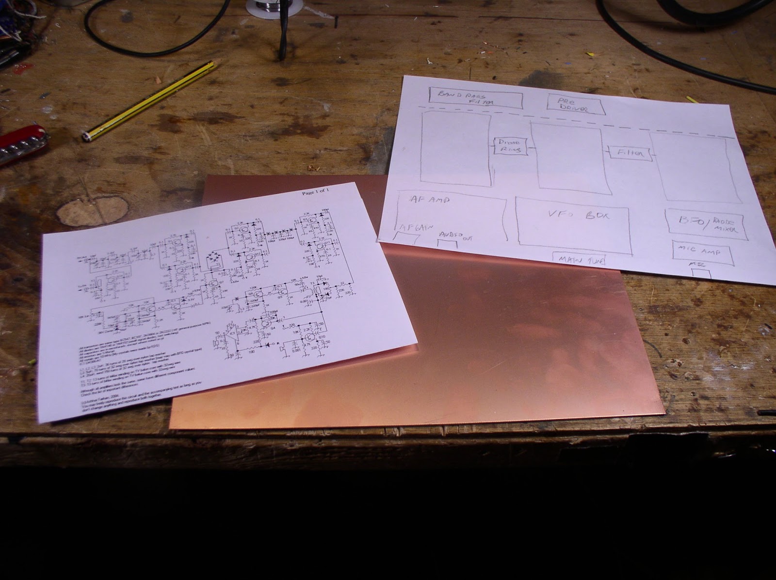
In the second amp (used in a 17 meter SINGLE Sideband rig) I used FT-50-43 cores for T1 and T2. The bigger gores were a little easier to work with. I glued them vertically to the copper clad board. For T3, I again went with 4 FT-37-43 cores. (I tried using 4 FT-50-43 cores for T-3, but I found that output was low, so I went back to the smaller cores for T3). Note that on the second amp, I put some insulation between the heatsinks and the copper clad board (gorilla tape) — I was worried about possible short to ground if the anodized layer on the heatsinks got breached.

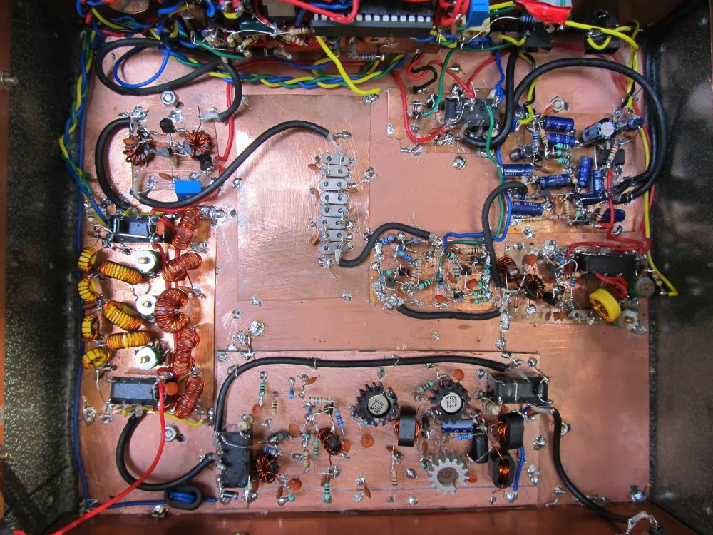
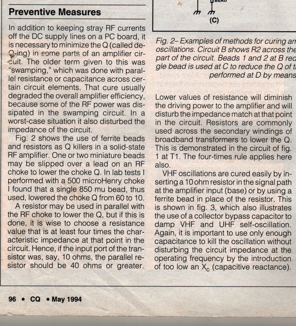
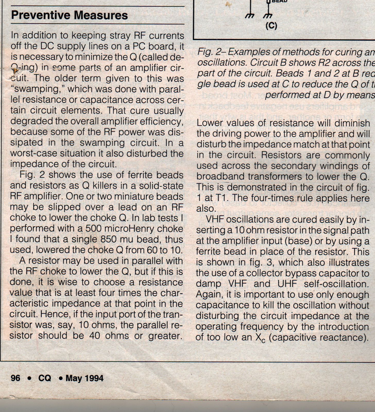
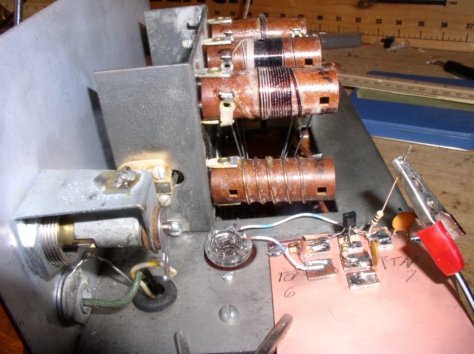
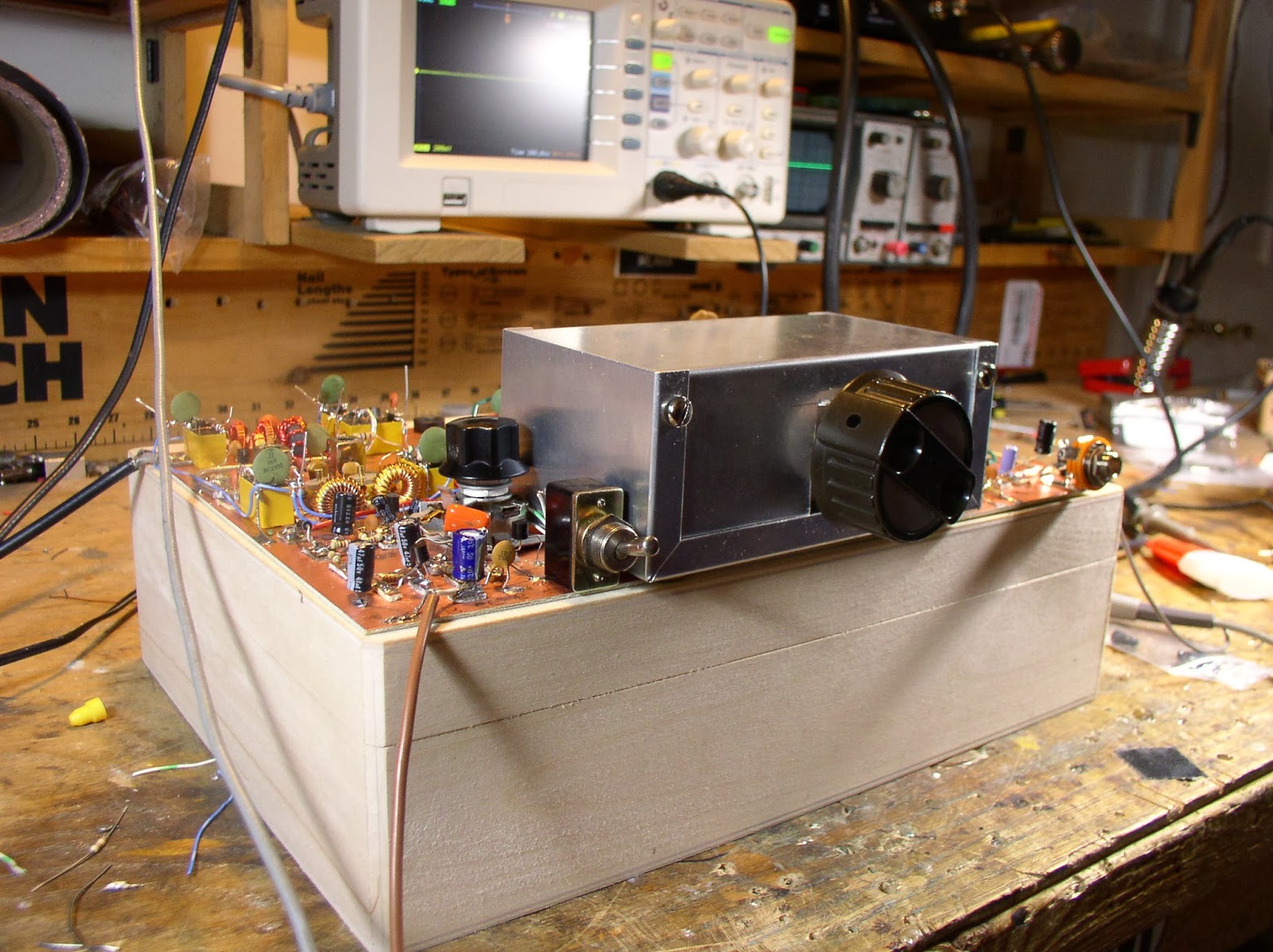
In building my amps, I used the photo on Farhan’s Phonestack page as my guide.

As is always the case with amps that I build, I found that a certain amount of “taming of the beast” had to take place before I got the devices stable. This is certainly the result of the kind of homebrew devices into which they are being inserted! Following advice from Doug DeMaw, I made liberal use of ferrite beads. I put one on the lead carrying 12 volts to the amp board. I put another on the lead from the 12 volt line to the final’s RF choke. And I put one on the line carrying the .6 volt bias to the secondary center tap of T2.

I put a bit of shielding (copper-clad board) between the low pass filter and T3.

These steps allowed these amps to work nicely with my contraptions.

As long as we are talking about JBOTS, I have a question for the group:

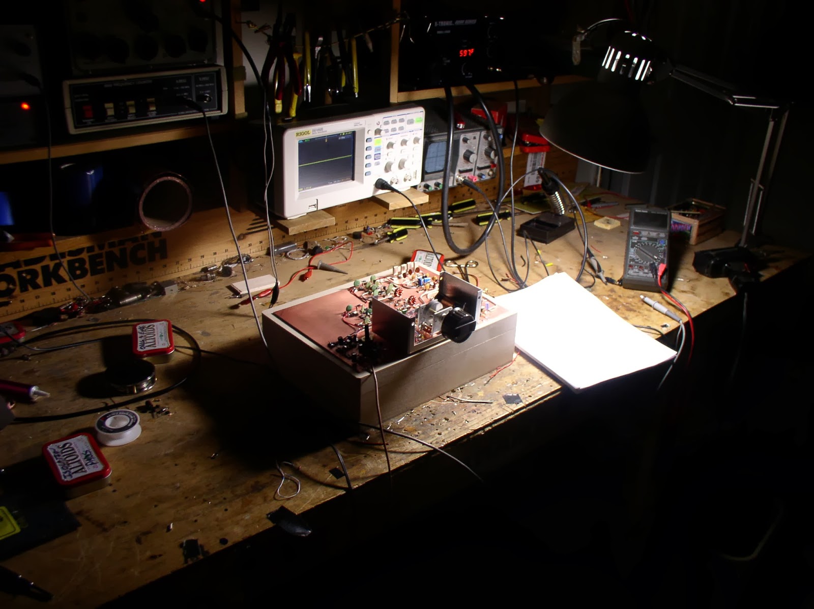
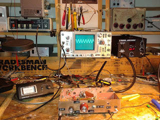
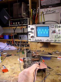
On my second amp, I noticed that the output was a bit lower than it should have been — only about 1.5 watts. I did a lot of troubleshooting, then I finally checked the bias currents in the first two stages. I found that BOTH were running at about 50 ma.

I looked at Farhan’s JBOT notes and found that the second stage is supposed to be running at 100 ma. I found that the base bias voltage on the second stage was 1.13 volts, while the first stage had 1.9 volts on the base. That didn’t seem right.

I then turned to the bias.exe program that comes with EMRFD. I plugged in the values from the JBOT schematic and, sure enough, the predicted collector bias current was 50 ma, not the 100ma the design was looking for.

Using that program, I made some changes to the base resistor in the second stage. I found that with 150 ohms instead of 100 ohms, the collector bias current goes up to the desired 100 ohms. This also seemed to bring power output up to the desired range of 3-4 watts (output should be a bit lower at 18 MHz, right?)

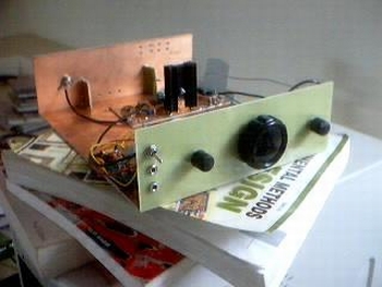
More info (and pictures) on my JBOT adventures can be found here:
http://soldersmoke.blogspot.com/search/label/JBOT

GOOD LUCK WITH YOUR JBOTS!
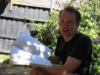
73 Bill N2CQR
http://soldersmoke.blogspot.com

Our book: “SolderSmoke — Global Adventures in Wireless Electronics”http://soldersmoke.com/book.htmOur coffee mugs, T-Shirts, bumper stickers: http://www.cafepress.com/SolderSmokeOur Book Store: http://astore.amazon.com/contracross-20