SolderSmoke Podcast 176: Knack-Related Conditions: Termination Insensitivity, Sideband Inversion, Dongle Modification, Area 5351 Conspiracy Disorder

SolderSmoke Podcast #176 is available! (And it is GOOD!)

http://soldersmoke.com/soldersmoke176.mp3

16 May 2015

Bench Update:
Pete releases some magic (amplifier) smoke
Pete’s new termination-insensitive transceiver makes first contact
Bill goes Yaesu (well, just a filter)
Juliano Mill-Pad boards
Termination Insensitivity is not a personality disorder!
Flip those Bilat Boards! Pete’s cool technique for bilat building
Bill’s project notebook and stage testing
Installing the W6JFR EMRFD SBL-1 Bal-Mod Mod

AREA 5351: Myths, Urban Legends, and Conspiracy Theories about the Si5351

A Rule of Thumb for Sideband Inversion

Dongle Madness and the Dangers of Dongle Modification
What is a dongle?
24 Mhz to 1.7 GHz right out of the box
Modification for 0-29 MHz
Tapping the IF of a Drake 2-B
Getting another one for VHF-UHF
Dongling Meteors, Satellites and Airplanes

SPRAT cover AD9850 in 1988! Three cheers for SPRAT (and QQ and QST).

Elecraft’s new Rig

Our book: “SolderSmoke — Global Adventures in Wireless Electronics” http://soldersmoke.com/book.htm Our coffee mugs, T-Shirts, bumper stickers: http://www.cafepress.com/SolderSmoke Our Book Store: http://astore.amazon.com/contracross-20

BITX DIGI-TIA Build Update #2 Installing and Testing Yaesu SSB Filter

Termination Insensitivity. It sounds like some sort of psychological problem, but it is not!

Our book: “SolderSmoke — Global Adventures in Wireless Electronics” http://soldersmoke.com/book.htm Our coffee mugs, T-Shirts, bumper stickers: http://www.cafepress.com/SolderSmoke Our Book Store: http://astore.amazon.com/contracross-20

Termination Insensitive BITX Amps

Back in 2009 Wes Hayward and Bob Kopski designed a termination insensitive amplifier block for use in BITX-like transceivers. Farhan urged me to use it. The advantage of this design is that the input impedance stays at 50 ohms no matter what you hang off the other end. That’s very helpful, especially when you start trying to get specific impedances at the ends of crystal filters. I’m planning on using this circuit in my next BITX. This morning I was playing around with it in LTSPICE. The “mirror” feature in that program is quite helpful when you are working on circuits like this!

Here is the article by Wes and Bob that describes this great circuit:
http://w7zoi.net/bidirectional_matched_amplifier.pdf

Our book: “SolderSmoke — Global Adventures in Wireless Electronics” http://soldersmoke.com/book.htm Our coffee mugs, T-Shirts, bumper stickers: http://www.cafepress.com/SolderSmoke Our Book Store: http://astore.amazon.com/contracross-20

VK3MO’s 20 Element Monobander for 20 Meters!

Ian VK3MO was booming in from Australia this morning. No wonder: he has a 5 over 5 over 5 over 5 array on a rotatable tower. He can get a 3 degree takeoff angle with this antenna and I think I heard him say that he is working on another so that he can get a one degree takeoff angle. He was also using a using a Collins 30L1 linear. Lots of soul in that old machine!
At one point in our QSO, I turned off my .12 kW amplifier. He said I was still 58-59 with 3-4 watts.
And Ian is a homebrewer! He has built a number of transceivers and has another one in the works. I told him about the BITX and he printed out Farhan’s article (to read later). He tells me that he has heard Peter Parker, VK3YE, on the air.
In this QSO, Ian was using a modern commercial rig, but wouldn’t it be great if we could get him to connect a homebrew sideband rig to that big antenna. Go for it Ian!

More on Ian’s antenna here: http://vk6ysf.com/vk3mo_visit.htm

Our book: “SolderSmoke — Global Adventures in Wireless Electronics” http://soldersmoke.com/book.htm Our coffee mugs, T-Shirts, bumper stickers: http://www.cafepress.com/SolderSmoke Our Book Store: http://astore.amazon.com/contracross-20

The Original BITX 20 — Designed at 35,000 Feet in 6 hours, Built in India in 3 Days

I came across what appears to be an early version of Farhan’s description of the design and initial construction of the BITX 20 (see below); this version has some interesting information on the origins of this important rig. The picture below shows the designer himself working on that first BITX20. It is from a CNN video. I know Farhan is sick of seeing this old video, so I present here only the shot of the designer’s hands at work on the original transceiver.

Some thoughts from the designer, Ashhar Farhan, VU2ESE:

This transceiver was designed during a six hour flight from Europe with paper, pencil and the basic calculator built into my cell phone. It was soldered in three sittings over three days. Very little went wrong during the construction. It was one of those easy designs. The only mistake that I made during construction was that I soldered one of transistors in reverse. The design worked as ‘advertised’. I guess that extensively using feed back amplifiers provides designers with greater repeatability. Also, I realized, a little late in life though, that detailed forethought and ‘mental’ home-brewing is important for a clean design.
The linear chain was initially unstable. It tended to oscillate in the 14MHz band as well as around 500 KHz. I traced the 14MHz oscillations to a choke that I was using at the output of the balanced modulator. It has been removed. The 500 KHz oscillations were because of excessive gain in the driver and pre-driver stages. From 5 ohms, the emitter degeneration has been increased to 10 ohms and better bypassing on the power rail has eliminated the oscillations.The receiver is as hot as I need it to be on 20 meters. Signals from USA, Europe, South Africa and of course India were heard with clarity reminiscent of a clean Direct-conversion receiver on the first evening. The transmitter is powerful enough for local rag chew and it is a modest challenge for DX. VU2PEP has an excellent two element beam at 20 meters at about 40 feet height. DX is easy for OM Paddy who uses the rig regularly. We netted LA2FKA within the first 20 minutes of firing up the rig.
No, I don’t offer PCBs. I don’t repair rigs. I don’t offer kits. I might do a PCB for this rig (I hate PCBs, they hamper experimentation).
This transceiver is dedicated to the memory of OM Juggie, SK (VU2JH) who was a great organizer of India hams, he wrote technical articles in Electronics For You magazine about amateur radio, spurring many to take on ham radio as a hobby. He organized the Millennium Ham Meet in the year 2000. He was always searching for a good and simple homebrew SSB transceiver. He died young. He gave me my first morse key.

Jagdish, VU2JH

Our book: “SolderSmoke — Global Adventures in Wireless Electronics” http://soldersmoke.com/book.htm Our coffee mugs, T-Shirts, bumper stickers: http://www.cafepress.com/SolderSmoke Our Book Store: http://astore.amazon.com/contracross-20

World Radio Day! Article with Farhan

The Hindu did a nice article on World Radio Day. They wisely featured someone with a true case of The Knack, someone with a strong emotional connection to radio and radios: our friend Farhan.

http://www.thehindu.com/features/metroplus/thank-you-for-the-radio/article6886601.ece

Our book: “SolderSmoke — Global Adventures in Wireless Electronics” http://soldersmoke.com/book.htm Our coffee mugs, T-Shirts, bumper stickers: http://www.cafepress.com/SolderSmoke Our Book Store: http://astore.amazon.com/contracross-20

A Thatched Roof, Some Palm Trees, A Dipole, and a Homebrew Rig


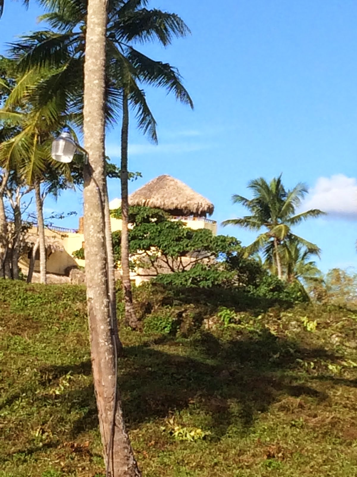
Look at the drawing above. That is the banner logo of Rod Newkirk’s column in QST magazine. For many years Rod regaled us with exciting reports on the activities of intrepid foreign radio amateurs, transmitting from exotic locations using ingeniously devised homebrew radio equipment. Look at the picture on the left side. See the palm trees? See the thatched roof shack with the dipole antenna? Well, that’s pretty close to what it was like for me out on the Samana Peninsula in the Dominican Republic last month.

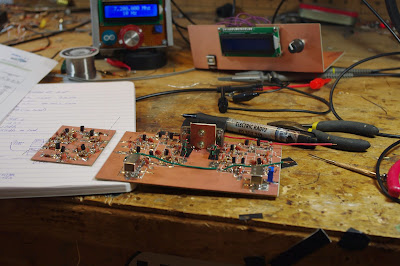
I set up the station under the thatched roof in this picture:

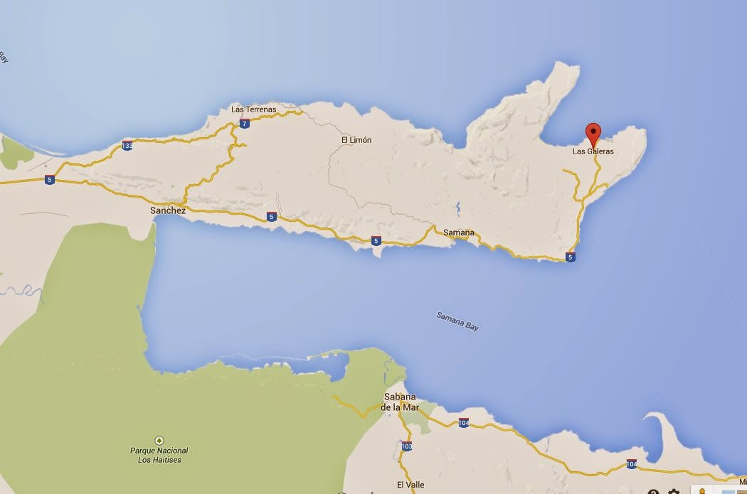
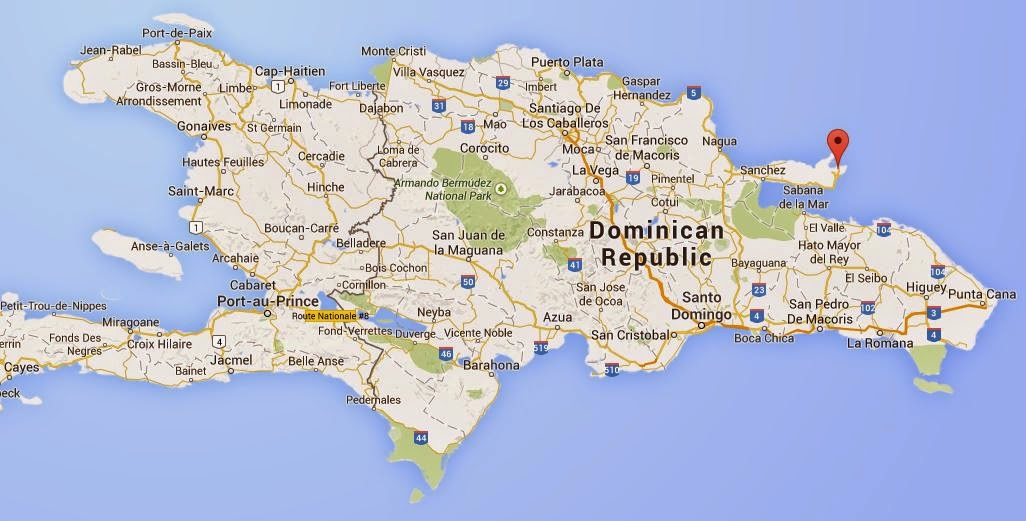
The red pins mark the spot:

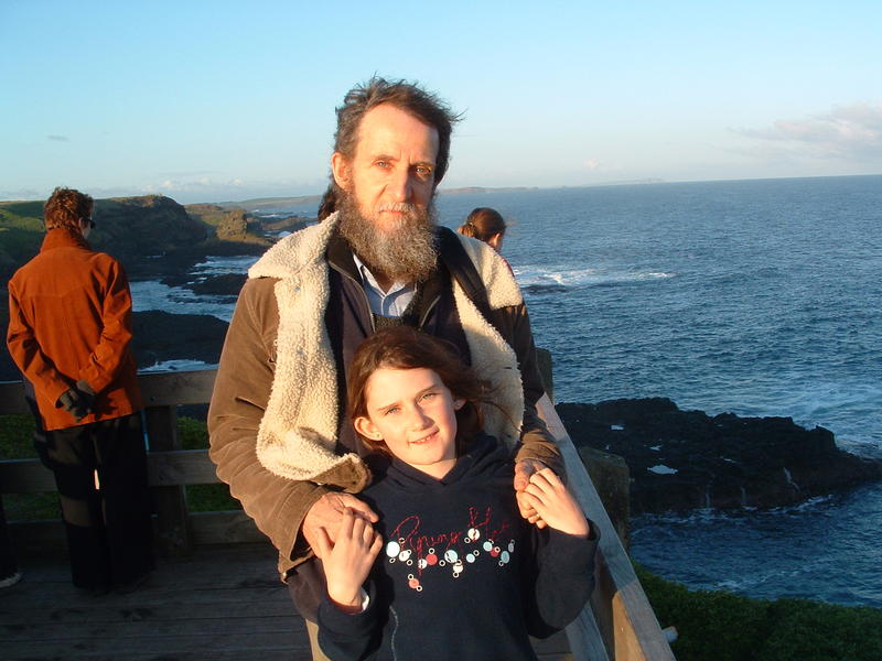
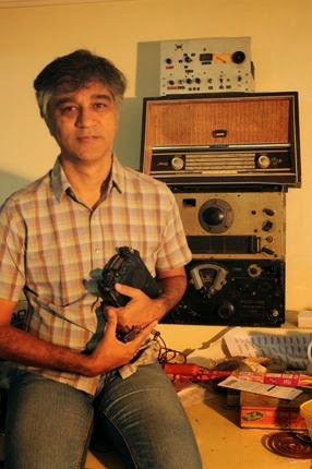
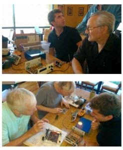
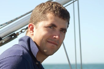
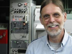
Here I am, tuning the rig while looking across Bahia Rincon:

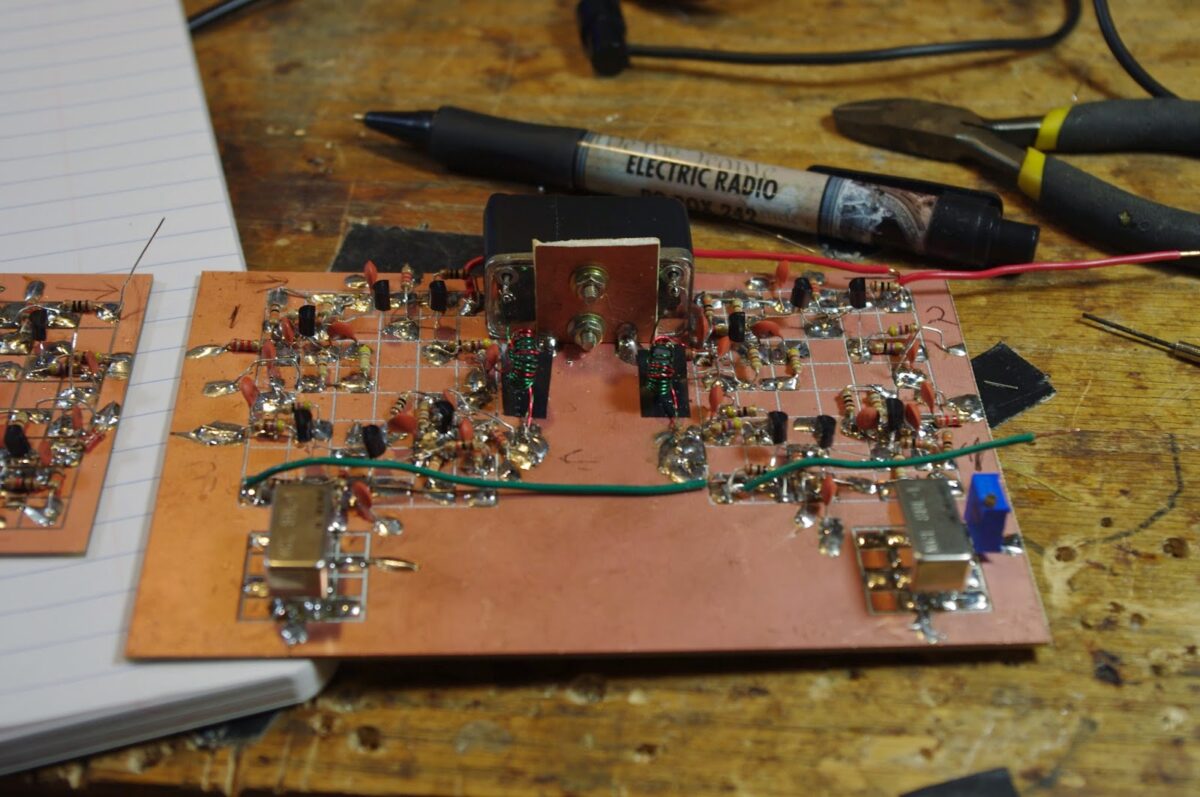
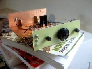
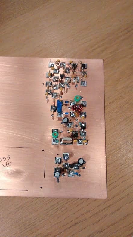
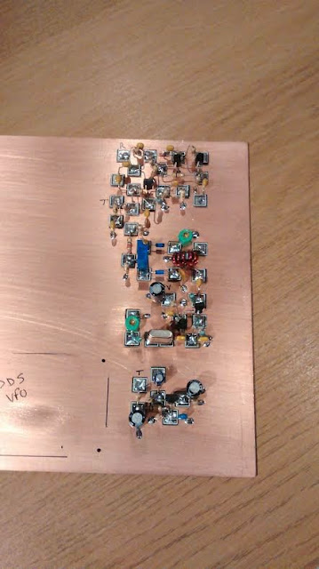
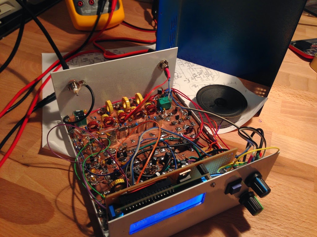
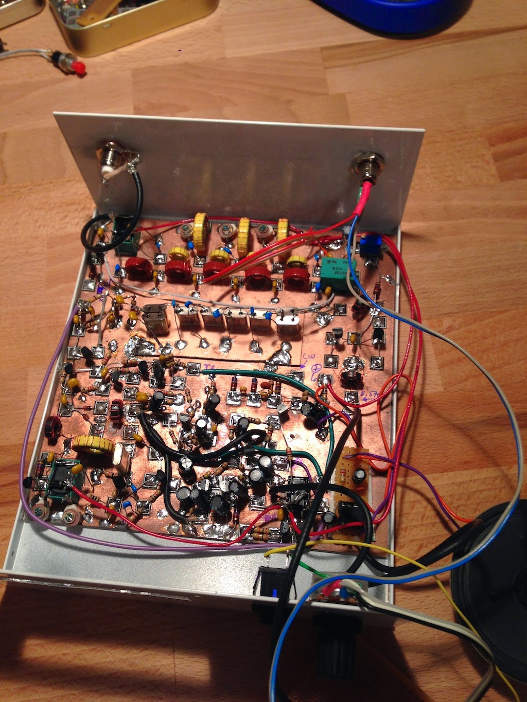
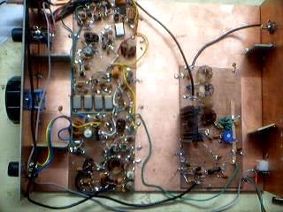
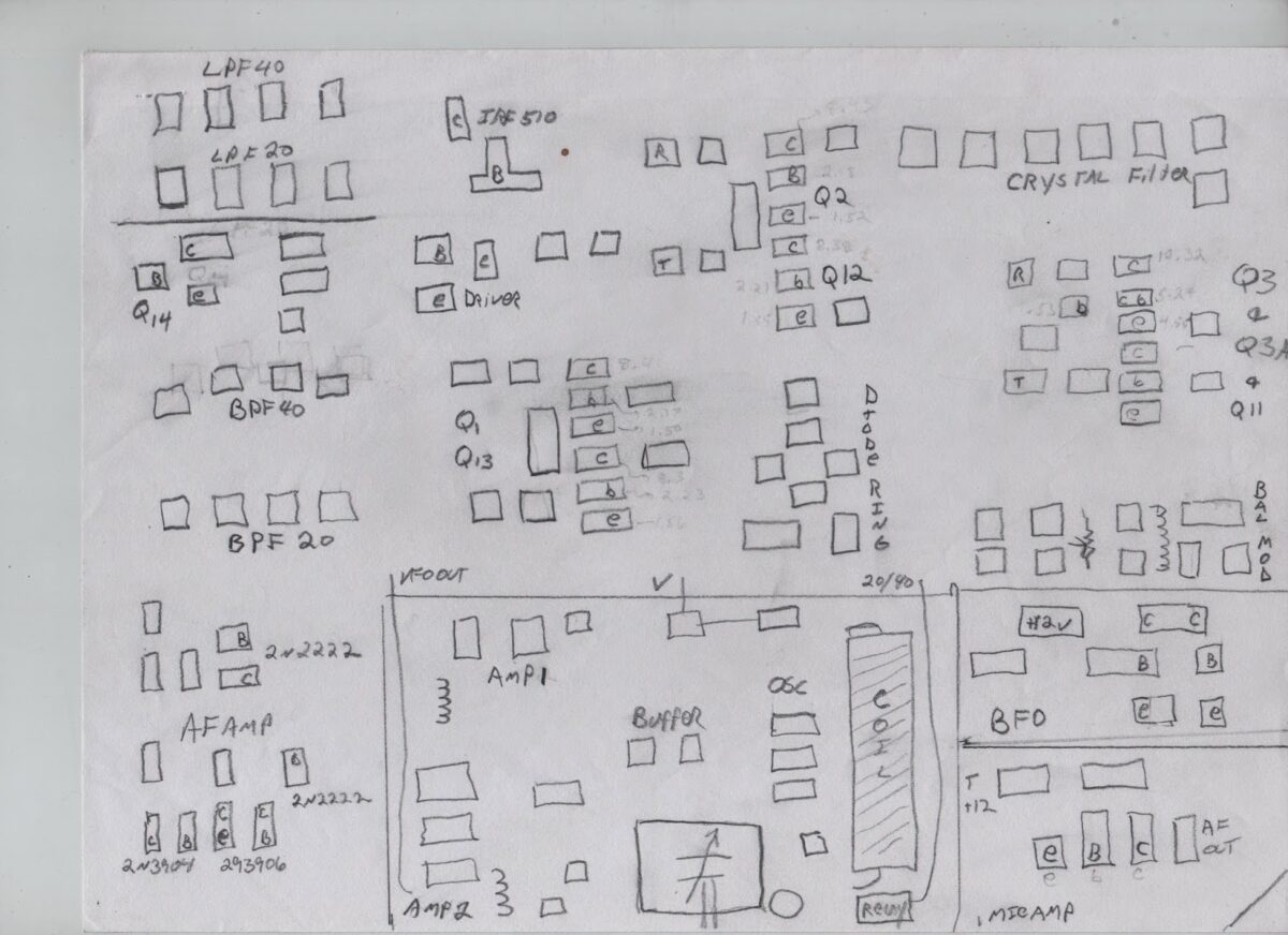
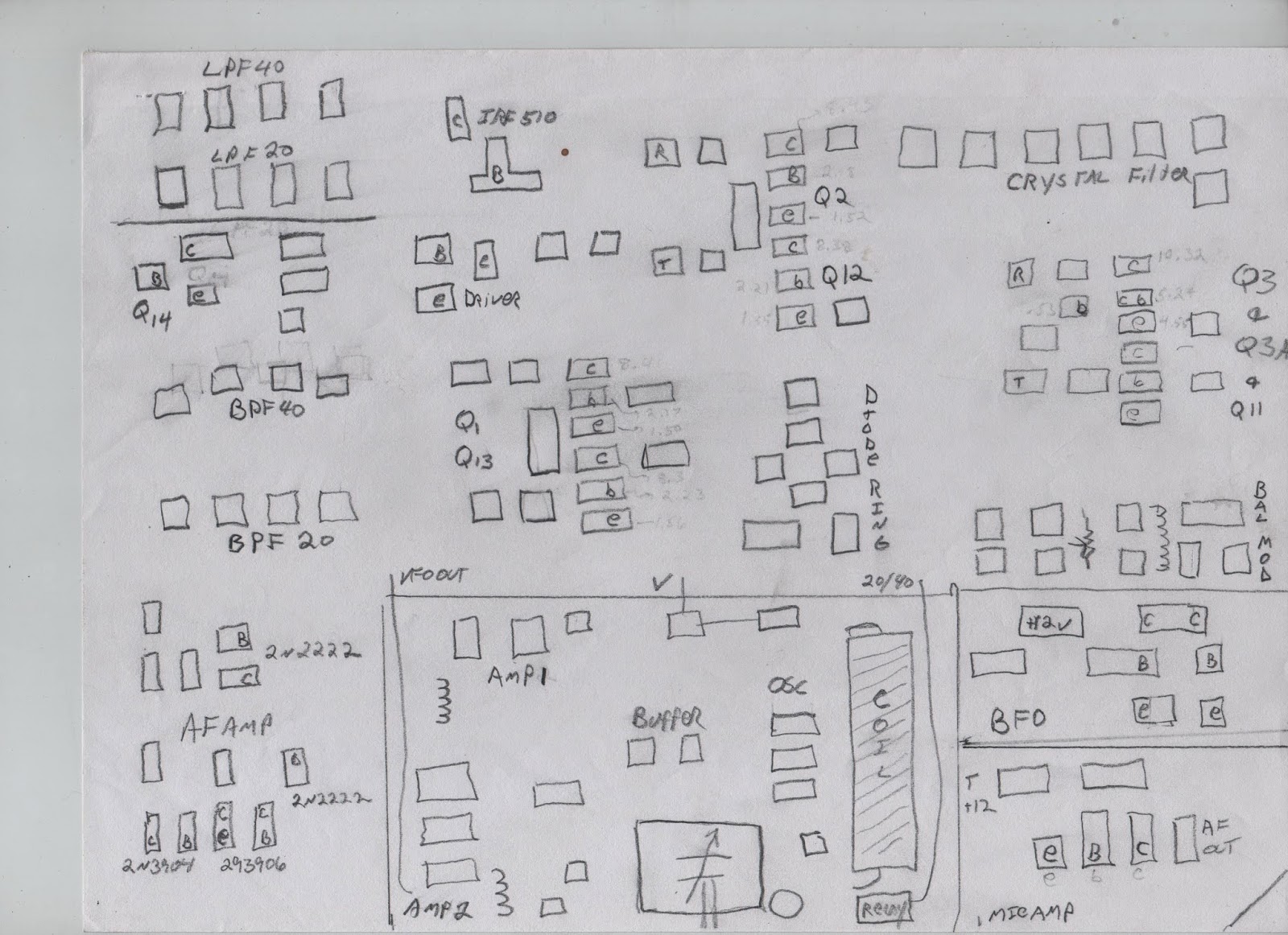
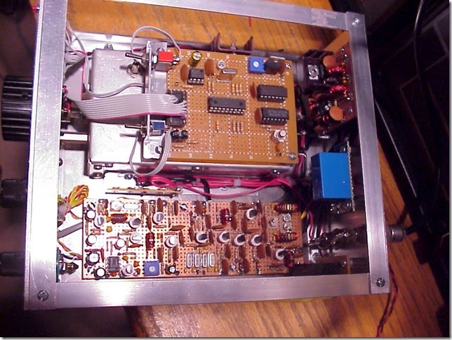
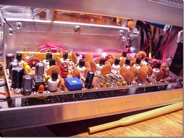
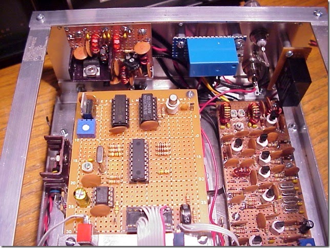
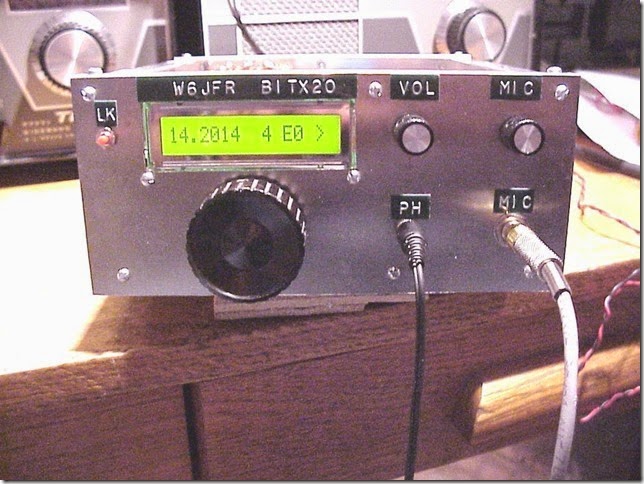
The rig was my Azores-built, oft-modified, NE602-based, ceramic resonator DSB transceiver with a recently added India-designed BITX IRF510 RF amplifier chain. A little article I wrote about the ceramic resonator VXO was featured in SPRAT 127. My antenna was a half wave dipole strung up in the thatched roof. Power came from 10 AA Batteries. So this was the Double A, Double Sideband, Dipole DX-pedition.

I had given some thought to building an SSB rig for this trip, but because of the efforts of Peter Parker, VK3YE, I felt compelled to take a DOUBLE Sideband rig with me to the beach.

Here is an old (2006) video on the rig. The power amplifier has been significantly modified:


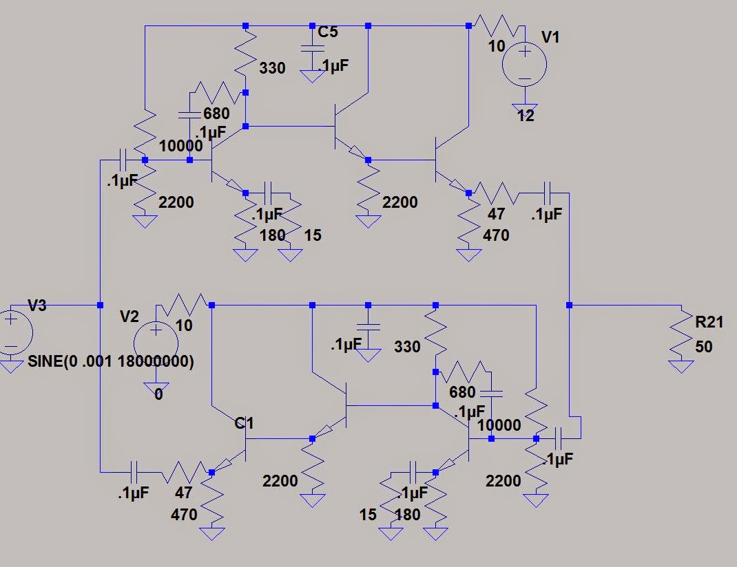
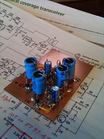
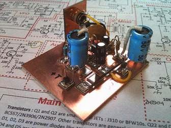
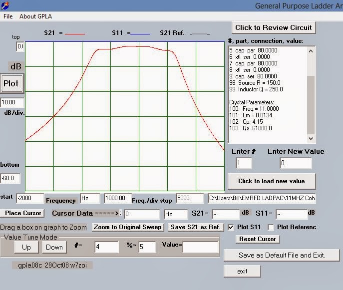
Here is some more information on the rig, including a schematic for the receiver and the SPRAT article on the Variable Ceramic Oscillator:

http://www.gadgeteer.us/PORTABLE.html

Here is the log book for my contacts.

17 DECEMBER 2014
W1JPR PAUL MT. DESERT ISLAND MAINE
8P6AE (BARBADOS) COULD BARELY HEAR ME, BUT GOOD QSO

18 DECEMBER 2014
N4USA DAVE IN FLOYD, VA. FAIRS NET. (KK4WW.COM)
KE4UGF DON ALSO FAIRS, NICE GUYS. FUN CONTACTS!
KA4ROG ROGER NORTH OF ORLANDO

19 DECEMBER 2014
WB2HPV GUIDO TALKING TO ITALIANS EVERY MORNING FROM WAYNE NJ. HE HAD TROUBLE HEARING ME.
CONDITIONS SEEMED POOR, BUT I WAS HEARING AUSTRALIAN STATIONS
W8GEO GEORGE IN THE INTERCON NET. HEARD ME. ALSO ON INTERCON: KA4AOQ AND 6Y5MP (JAMAICA) ALSO HEARD ME.
N4PD PAUL
W3JXY/4 NAT IN KEY WEST
N1FM TOM, NORTH OF MIAMI SOLID QSO.
KM4MA PAUL IN ORLANDO WITH MARITIME MOBILE NET.

20 DECEMBER 2014
NA2LF LLOYD IN NY
WB8YWR JIM IN DALLAS
KM4MA.
W1AW/3 IN MARYLAND (TOOK ME A WHILE TO GET HIM)

21 DECEMBER 2014 NICE 4 WAY SPANISH LANGUAGE QSO:
KI4PZE MIGUEL
CO8OT JUAN IN SANTIAGO DE CUBA
WA4RME RAFA IN CHARLESTON S.C.

C08KB MARCO IN CUBA


Here is a short video showing the station and the location. Note the little birds (Golondrinas or Swallows) flying by. They nest in the thatched roof. They often got confused and flew inside the house. Billy and Maria rescued many of them. Whales breed in this bay in January and February. There are also manatees. It is really a beautiful place.

There were obviously other attractions (!) so I didn’t spend a lot of time on the radio — just a half hour or so every now and then. But it was really very satisfying to carry this little homebrew device with me, set it up in this amazing place, and use it to send my voice across mountains and hundreds of miles of ocean. I built this rig in the Azores and have used it in the UK, France, Italy and the Dominican Republic. It contains circuits devised by members of the British QRP club and by my friend Farhan in India. The ceramic resonator circuit is something I cooked up on my own. The microphone is from my old Sony Walkman and the pen that serves as its support is from that wonderful magazine “Electric Radio.” In short, there is a lot of soul in this little machine. And it was a lot of fun to take it to the beach.

Thanks to Elisa for finding us this wonderful place. And to Rod Newkirk and QST for the DX inspiration.

Our book: “SolderSmoke — Global Adventures in Wireless Electronics” http://soldersmoke.com/book.htm Our coffee mugs, T-Shirts, bumper stickers: http://www.cafepress.com/SolderSmoke Our Book Store: http://astore.amazon.com/contracross-20

Colin’s BITX is Receiving!

Wow, quite a bit of progress at M1BUU since our last look (see below). I must admit, that Arduino DDS board looks quite nice sitting there in the VFO territory. In his original BITX20 article Farhan recommends a pause before the construction of the final portions of the transmitter — the builder is advised to sit back and enjoy the receiver that has just been created. Colin is at that point! Congratulations Colin. He has noted that his board is a bit(x) smaller than mine. Maybe he should stick with Farhan’s recommendation and build the PA and driver on a separate board. This will also help prevent the dreaded oscillations — no need to tempt fate or anger the radio gods!
Hi Pete,

Another great SolderSmoke episode this weekend, I really like the humour between you and Bill! I listened to SS whilst melting solder on my BITX project.

I had really wanted to get my BITX working as a receiver before the end of the weekend, but Lewis Hamilton and his (successful) bid to become Formula 1 World Champion, put an end to that idea! I also decided that I wanted to buy some better quality capacitors for the band pass filter, so I’ve ordered them today.

I fired up the receiver chain for the first time this evening from where the BPF should be, right through to the AF amp, I’m pleased to report that I seem to have created a working superhet receiver! I heard some BC breakthrough at certain points of the tuning range and the rig receives the second harmonic of my Rishworth Buildathon 40m transmitter beautifully (on right part of dial too!). I hadn’t tested the RX IF amps or AF amp before, but they seem to be doing just fine.

I’m so pleased to have got so far, and I’m very pleased with the build. That big copper clad board doesn’t look so big now, but I think I have room for the TX/RX switch, BPF, RF driver, RF PA and LPF which I still need to add.
Thanks for the encouragement and advice so far, I doubt I’d be feeling so elated at this point without it!
This is going to be a really cool rig!
73, Colin M1BUU

Hi Colin,
Two words come to mind: Absolutely Superb! Wow that is such a work of art. I may never show another one of my projects as you have set the standard and benchmark.
You also have demonstrated building from the back end which we discussed in SS168. Now what you have built is a part of the test system.
Really outstanding. Be sure and video your 1st qso and share on You Tube.
Bravo!
73’s
Pete

Our book: “SolderSmoke — Global Adventures in Wireless Electronics” http://soldersmoke.com/book.htm Our coffee mugs, T-Shirts, bumper stickers: http://www.cafepress.com/SolderSmoke Our Book Store: http://astore.amazon.com/contracross-20

Colin’s BITX

With advice and tribal knowledge from N6QW and MeSquares from W1REX, Colin M1BUU, is making excellent progress on his BITX. I see that he has some territory on the board reserved for a DDS VFO. That’s fine, but here’s and idea for Colin and other builders: Why not build it with the standard VFO first and then add the DDS or Si570 VFO later, perhaps as an external accessory? That way you get the experience of building an LC VFO — the full BITX experience.

Yea, it is hard to imagine Paul M0XPD as a newcomer to the hobby such a short time ago — he is definitely now in the ranks of the esteemed digital Elmers.

And yes Colin, we do hope you avoid unwanted oscillations. Because of Farhan’s great design you have a good shot at avoiding this plague. But be prepared OM. It happens to the best of us. A lot. Stiff upper lip! Never give in!
*************
Hi Bill,
I enjoyed your video about your Arduino experiment. You bet me to it! I’m really looking forward to getting my version of an Arduino powered BITX up and running.
Steady progress is being made, yesterday I added my first bidirectional amplifier to the build. I now have the mic amp, BFO, balanced modulator and first amp completed. I tested the BFO on it’s own and got a respectable looking signal out of it and with a good swing below 10MHz.
Next I need to add the crystal filter, second IF amp and mixer. Pete’s video will help for the mixer! BTW, I’m using the ver3 schematic but I intend to use the ver1 band pass filter.
I set out building the circuit following the N2CQR layout diagram but I’ve already run short on space! I do have a good excuse though, my board is smaller than yours (10″x6″).
Despite my best intentions, I’m falling back towards old habits of making my circuits physically small. I’m using MeSquares in order to try and force myself to space things out a bit. I do hope that I don’t end up with any unwanted coupling!
I must try hard to leave lots of space between the next bits of circuit.
I was listening to SolderSmoke 104 today and Paul M0XPD was introduced as a new ham. Little did we know that Paul would become such a big player!
73, Colin M1BUU

Our book: “SolderSmoke — Global Adventures in Wireless Electronics” http://soldersmoke.com/book.htm Our coffee mugs, T-Shirts, bumper stickers: http://www.cafepress.com/SolderSmoke Our Book Store: http://astore.amazon.com/contracross-20

Mailbag: Coils Wound Backwards, Last QSO 1981, Visions of Transistors Keeping Him Awake. Paul has THE KNACK


Hi Bill

I’m just getting back into ham radio after 33 years (last QSO: 1981),
want to do it all through homebrew, seem to have the same mindset as
guys like you and Frank K0IYE, bought your book [love it and Frank’s],
and just “discovered” the Soldersmoke podcasts. I’ve been listening to
them with one ear as I bike to and from work (about 40 minutes each way, so it’s almost perfect). I’m employed as a digital geek, but yearn for the days of DeMaw’s prime (worked him once when he was W1CER), when the 40673 ruled. I’m very glad that, 40 years later, people like Farhan can weave discrete analog wonders, even if they later choose to use digital *control* (NOT DSP! No!).

I had to start somewhere with your podcasts archive, so I started with
2014 and really enjoyed your struggles with the Herring-Aid 5. My 1st
receiver was the “DC 80-10” by DeMaw from somewhere around 1970 in QST or the Handbook — used a CA3028 as the product detector — and I had similar struggles. While listening to it, I immediately thought “you wound the feedback coil backwards, you idiot!”

I got my license back in March 2014 and want very badly to get back on
the air with a homebrewed, or at least minimally-kitted, station. I’ve
built the receiver: David White’s (WN5Y) Beginner’s and Experimenters
receiver[1] heavily modified, have a long wire antenna up, a decent RF
ground, and all the parts I need for QRP z-match tuner, swr meter, T/R
switch, sidetone, and IRF510-based transmitter. Target: 40m CW by the middle of December, 30m in the couple of months after that with a
fully-Manhattan-style Barebones Superhet and another IRF510
transmitter. Then one of these BitX things. It’s been a couple of
decades since I felt that there weren’t enough hours in the day. Some
nights I can’t sleep, what with all these transistors and simple analog
ICs whirling around…

Anyway, keep it up, I’ll be listening.

— Paul Lender, AD0HQ

[1] I built an Arduino/AD9850 DDS — a la AD7C — and used it to tune a
4-crystal filter (10-cent crystals from Tayda!) for the receiver with
the same Rigol scope that you use. I tried, really tried, to do it with
an analog RF signal generator. Change is good. Change is good.

Our book: “SolderSmoke — Global Adventures in Wireless Electronics” http://soldersmoke.com/book.htm Our coffee mugs, T-Shirts, bumper stickers: http://www.cafepress.com/SolderSmoke Our Book Store: http://astore.amazon.com/contracross-20

Thomas KK6AHT’s Pacificon Minima Presentation: Noodling! And Maxima Inspiration!

Wow, the Minima presentation by Thomas at Pacificon was really great. I think he had exactly the right tone and tech level for the digitally-savvy California audience. His very open description of the ups and downs of his Minima build will surely lure in some new builders, and will at the same time prepare them for the travails ahead! Great stuff. I like the mention of Pete’s “noodling.” Thomas obviously gets it. And he obviously has THE KNACK. Thanks Thomas!

Thomas has posted his slides and (MOST IMPORTANT) the audio of his presentation. Just click on the BIG ORANGE play arrow below the slides. You folks will love this:

http://www.sarfata.org/2014/10/Minima-Presentation-at-Pacificon/

Our book: “SolderSmoke — Global Adventures in Wireless Electronics” http://soldersmoke.com/book.htm Our coffee mugs, T-Shirts, bumper stickers: http://www.cafepress.com/SolderSmoke Our Book Store: http://astore.amazon.com/contracross-20

Thomas’s Magnificent Minima

Wow, Thomas’s page makes me really want to build a Minima. Note the Manhattan style with Rex Harper’s Me-Pads. Excellent. Thomas provides a really great stage-by-stage description of the project with the kind of candid descriptions of mistakes that SolderSmoke listeners are so fond of!

http://www.sarfata.org/ham/minima/

Thomas himself has an interesting “international brotherhood” personal history:

http://www.sarfata.org/about.html

Our book: “SolderSmoke — Global Adventures in Wireless Electronics” http://soldersmoke.com/book.htm Our coffee mugs, T-Shirts, bumper stickers: http://www.cafepress.com/SolderSmoke Our Book Store: http://astore.amazon.com/contracross-20

Harv’s Minima

Good Evening Bill & fellow Solder-smoke friends,
Well, I’m following the pack. I began gathering items for the Minima Transceiver back in March 14. There had been a good bit of strong back-N-forth discussions on the Minima Blog about what works and what doesn’t work. Some circuit refinements had been agreed upon while other were left to individual preferences. So, I decided to just be silent an learn from the experts. As a result, I did several months of observing before I took the plunge. While my efforts are not nearly as aggressive as others, I decided to forge a much slower path to success.
In my own quirky way of doing things, I kitted each module, measured all the parts statically, laid out the components, and finally built & tested each assembly before going to the next.
As a result, the learning’s were great and the performance of each section equal or better than my expectations.
I went the Manhattan Style this time but, I have purchased several sets of Minima PCBs to use in the future. As I see it, there is a lot more solder melting ahead.
Bill, building radios is NOT DEAD yet. That desire to get back to the golden days of home-brewing still lives on.
At the end of the Memorial Weekend, this is my current Minima progress…
· Construction of all 3 Audio Stages now complete (see photos)
· The Microphone Pre-Amp is now awaiting voice testing
· Audio Amplifier and Final Amplifier have been tested together
· The results of audio testing has been superb for all stages thus far
· 3 complete sets of Micro Relays have been order and I’m now awaiting their arrival
· 24 – various ferrite and powered iron cores arrived several weeks ago, these are the heart of the front-end RX/TX stages
· 100 – 20 Mhz. crystals have arrived and await characterization
· 25 – 8” Male to Male SMA Cables have arrived this weekend, will need to order 15 – 4” Male to Male SMA Cable Assemblies next
· 5 – 12” X 15” Copper Clad Boards have arrived this weekend
· 25 –J310 N-channel J RF Power FETs were ordered and arrived this weekend, these are used in the Mixer Stage

Final Audio Stage
Audio Amplifier Stage

Microphone Pre-Amplifier Stage (see microphone connector mounted at rear)
I’m ready to begin kitting the Side Tone Oscillator and RX/TX Relay Stages.
The largest and most intense modules are yet to be tackled.
The Bi-Directional Amplifier has 34 parts alone. So far I have installed over 40 parts in the three modules I’ve completed…
I realize it is just a start but, I’m motivated to see this one project through to completion.
73’s & Happy Soldering
Harv -=WA3EIB=-
Albuquerque, NM.

Our book: “SolderSmoke — Global Adventures in Wireless Electronics” http://soldersmoke.com/book.htm Our coffee mugs, T-Shirts, bumper stickers: http://www.cafepress.com/SolderSmoke Our Book Store: http://astore.amazon.com/contracross-20

Parts Cost for BITX in India: $5 US (that’s buying all the parts!)


I knew that in India you could build a BITX for a few bucks, but I thought that this cost estimate assumed a fairly well-stocked junk box. Not true! This morning an e-mail from Farhan points out that even if an Indian ham has to BUY all the parts, he can get all of them for the equivalent of 5 dollars U.S.:

“Less than half a cent per resistor, less than a cent per capacitor, two cents per npn transistor and 50 cents for the IRF510. We use ‘tv baluns’ and tap washers for coils.”

And, from the original BITX design page:

The purpose is to address the need among Indian hams in particular for an SSB rig that is easily and cheaply built. My original aim was to keep the price under Rs. 1000. The current design brings the cost to well under Rs.300 (less than 7 dollars).”

Now, when you are talking to someone using a new $10,000 Yaesu/Icom/Kenwood rig, it might be a bit unkind to mention that your rig can be had for $5.

Our book: “SolderSmoke — Global Adventures in Wireless Electronics” http://soldersmoke.com/book.htm Our coffee mugs, T-Shirts, bumper stickers: http://www.cafepress.com/SolderSmoke Our Book Store: http://astore.amazon.com/contracross-20

Manhattan meets Hyderabad: Pad Pattern for my BITX 20/40

A rough guide to how I laid out the isolation pads on my BITX 20/40 board. The copper-clad board is 8 inches x 11 inches (22 cm x 28 cm). I just cut out the pads as needed using tin shears and scrap pieces of copper clad board. Gorrilla SuperGlue is my preferred adhesive. I will put this in the appropriate file on the BITX 20 yahoo group site.

Our book: “SolderSmoke — Global Adventures in Wireless Electronics” http://soldersmoke.com/book.htm Our coffee mugs, T-Shirts, bumper stickers: http://www.cafepress.com/SolderSmoke Our Book Store: http://astore.amazon.com/contracross-20

Pete Juliano’s Bilateral Rigs (with videos)

Hi Bill,
I was finally getting around to reading one of the recent SPRAT’s and saw a photo of your magnificent BITX17. Congratulations! A tip of the hat to Farhan for that very excellent design and it truly is a design that has traveled the world and made a radio available to many who otherwise would not be on the air.
It is a very robust design as I scratch built one in 2005 (or maybe 2006) and just for fun socketed every transistor so I could try various devices. I even had a bag of 2N706’s dating back to the late 1960’s. They all worked except for the carrier oscillator where I just couldn’t get enough swing in the oscillator to correctly place the CIO on the filter slope. That I attribute to the junction capacitance of the 2N706. By far the lowly 2N3904 that I bought for 4 cents each worked the best. Back when I built this I was W6JFR. Adding the EI9GQ frequency stabilizer really added a nice touch to the radio.
I should also tell you that when I built the radio my intent was to uses a piece of single sided copper vector board for the main chassis. It was the weekend and I didn’t realize the piece I had was not big enough for the project. So I took a piece of standard perf board and overlaid that on top of a piece of single sided copper PC board –AND hand drilled all of the holes – I went blind, cross-eyed and had a terrible hangover after consuming 6 beers in a short time span! See the photos below.
BTW I also built a 17M SSB transceiver using the bilateral amp stage from G4GXO as appeared in the SPRAT 128. That used a 4.9152 MHz IF and a 23 MHz Super VXO. In the case of the VXO I used 11.52 MHz crystals in the VXO and used a diode doubler to put the LO at 23 MHz. With the doubler –you get the bonus of 2X the frequency shift of the Super VXO. I also had made a custom set of crystals and used a small relay to switch those into the circuit and that essentially gave me almost the full SSB Band coverage. You can see that here
Also I have been using a simple bilateral stage consisting of a 2N3906 and 2N3904 and the results have been amazing. The latest work is a follow on to my shirt pocket transceiver and uses SMD components. See attached.
Here are some videos of the latest –which is now a two bander 40 and 20M. (Originally it was 75 and 40M)
Have fun – this is such a wonderful hobby!
73’s
Pete N6QW

Our book: “SolderSmoke — Global Adventures in Wireless Electronics” http://soldersmoke.com/book.htm Our coffee mugs, T-Shirts, bumper stickers: http://www.cafepress.com/SolderSmoke Our Book Store: http://astore.amazon.com/contracross-20

Farhan’s RM386 RF Amplifier

An RF amplifier inspired by a quest for an AF replacement for the LM386. I like it! Check it out:

http://www.hfsignals.org/index.php/RF386

Our book: “SolderSmoke — Global Adventures in Wireless Electronics” http://soldersmoke.com/book.htm Our coffee mugs, T-Shirts, bumper stickers: http://www.cafepress.com/SolderSmoke Our Book Store: http://astore.amazon.com/contracross-20

On the Origins of “Ugly”

Yesterday I posted a link to a Maker Blog article about a fellow who designed a DIY, junkbox, homebrew machine tool. I noted that in the book “The Ugly American” the hero also makes use of old engine blocks. Farhan commented on this, reminding me of the connection between “The Ugly American” and our beloved ugly construction method: This is from Todd’s (wonderful) QRP Pops site:

http://www.qrp.pops.net/ugly.asp

The Origin of the Term “Ugly Construction”

Roger Hayward, KA7EXM and Wes Hayward, W7ZOI coined the term “Ugly Construction” while writing the “Ugly Weekender” published in the August 1981 issue of QST. I asked Wes about this in 2009. The term was a takeoff from the 1958 book entitled The Ugly American by William Lederer and Eugene Burdick.

Our book: “SolderSmoke — Global Adventures in Wireless Electronics” http://soldersmoke.com/book.htm Our coffee mugs, T-Shirts, bumper stickers: http://www.cafepress.com/SolderSmoke Our Book Store: http://astore.amazon.com/contracross-20

BITX 2040 Build Update #10 : Fixing my Filter

That dip on the high side of the passband was bothering me. The GPLA crystal design program predicted it, and indeed, when I measured the performance of the actual filter, there it was. The rig was working fine — the receiver sounded fine and everyone tells me that it sounds great on transmit. But still, it bothered me.

So I started working out with the various crystal filter software packages.

This filter was — sort of — a Cohn Min-loss filter, but I had built it with four crystals and three shunt caps (80 pf each) and no series caps at the input/output. This morning I decided to see what would happen if I put the series caps in there. Here is what Wes’s GPLA predicted:

Wow, that looked a lot nicer. And the 150 ohm terminations seemed to be just about perfect for the BITX design — no need for impedance transformation. I heated up the soldering iron and searched the junkbox for suitable caps (I found 2 82 pf caps — close enough).

Here is what the results looked like (I didn’t measure insertion loss so the top of the curve is just the peak of the response curve).


Exactly as predicted! Thanks Wes! And thanks to Farhan for encouraging me to characterize my crystals and to use the available software

Now I have to go back and de-ripple the 5 MHz filter in my BITX 17.

Our book: “SolderSmoke — Global Adventures in Wireless Electronics” http://soldersmoke.com/book.htm Our coffee mugs, T-Shirts, bumper stickers: http://www.cafepress.com/SolderSmoke Our Book Store: http://astore.amazon.com/contracross-20

G0MGX’s Minima

Wow, Mark didn’t waste any time in building his Minima. FB OM. His web site has a lot of good info on this project: http://g0mgx.blogspot.co.uk/

Our book: “SolderSmoke — Global Adventures in Wireless Electronics” http://soldersmoke.com/book.htm Our coffee mugs, T-Shirts, bumper stickers: http://www.cafepress.com/SolderSmoke Our Book Store: http://astore.amazon.com/contracross-20