 The HW-8 rehab project of Ed, WA3WSJ, has led to a nice discussion on QRP-L about the possibility of using the HW-8 as a DSB rig. Mike, KL7R, did such a mod on his HW-8 many years ago and used it successfully in the field in Alaska. Read his story here:
http://kl7r.ham-radio.ch/hw8/hw8story.html
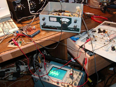
Nick, WA5BDU, and I have been discussing the possible need for an additional mod to put the HW-8’s final in linear mode. The picture above is of Mike’s rig, with the finals unbiased. Check out the scope. Looks pretty good to me!
Here’s the e-mail exchange:
I had the same thought regarding amplifier class, and Steve, WB6TNL also emailed the same observation.
The balanced modulator is inserted between the driver and final amplifier, which has no fixed bias and has its emitter grounded, so it’s definitely class-C. I do note that the balanced modulator is passive and probably has 6dB or more of loss, so you’re getting a pretty good drive reduction. And Mike said he adjusted the audio while watching the RF output until there was minimal flat topping on a scope. So I wonder if it’s possible to keep things fairly linear if the power is kept quite low?
At any rate, I love the idea. Here’s Mike in the 70s. He has an HW-8 he’s familiar with, and he’s reading SSDRA. Going over the simple DSB generation examples, he thinks — why not stick this in the RF train of my HW-8?
72-
Nick, WA5BDU
On 9/19/2011 4:36 AM, Bill Meara wrote: Nick: I enjoyed reading about your HW-8 adventure, especially the part about Mike’s work with this rig. I remember talking to him about it, and I’ve since come across some articles describing similar DSB mods. One thing that all of these plans lack, however, is a modification to the PA. It is Class C in the HW-8, and would need to be made linear for DSB service, correct? 73 Bill N2CQR
— On Sun, 9/18/11, Nick-WA5BDU wrote:
From: Nick-WA5BDU
Subject: Re: [QRP-L] WA3WSJ Heathkit HW-8 Rebuild Status
To: qrp-l@mailman.qth.net
Date: Sunday, September 18, 2011, 9:44 PM
Sounds like a great project (or projects!) Ed.
I’m working on an HW-8 also. Bought it at a hamfest this Spring at a
good price, but suspected it might have some issues. When I started
playing with it I noted that transmit power was down, the loading
control was stuck, and there was no sound from the receiver.
The receiver issue was the most challenging and I eventually tracked it
to a leaky transistor in the T/R circuit which was activating the mute
function even when key up. I suspect that the transistor’s problem may
have been due to the lack of a de-spiking diode on the T/R relay’s coil
so I added one.
So far I’m not keen on modifying the rig and am even keeping the RCA
connector (spent an outrageous $5 for a RCA to BNC adapter from Radio
Shack). Well, maybe not outrageous, but I’m pretty cheap. Other than the
diode, I did add a 1A fuse and a reverse polarized diode downstream of
it for reverse-polarity protection.
After going thoThe HW-8 rehab project of Ed, WA3WSJ, has led to a nice discussion on QRP-L about the possibility of using the HW-8 as a DSB rig. Mike, KL7R, did a mod on his HW-8 many years ago and used it successfully in the field in Alaska. Read his story here:
http://kl7r.ham-radio.ch/hw8/hw8story.html
Nick, WA5BDU, and I have been discussing the possible need for an additional mod to put the HW-8’s final in linear mode. The picture above is of Mike’s rig, with the finals unbiased. Check out the scope. Looks pretty good to me!
Here’s the e-mail exchange: ugh most of the alignment procedure (I don’t have a tool
that will reach the bottom coils of the dual-coil adjustable inductors),
the VFO looks good and the power output seems about right.
It was nice that QRP Afield and the Washington Salmon Run were going
right after I did my repairs, so I was able to make ten or so QSOs to
try it out. It also reaffirmed the idea that QSOs can come pretty easily
at 1 or 2 watts out — you don’t need the full pentawatt. I had my first
QSO with the rig the night before, when it was fitting that I worked a
guy running a HW-101 who said he also had a HW-8. Heath to Heath at
random — what are the odds?
I find that if I buy a used rig and have to work on it to get it going,
I develop a greater appreciation for it. If the repair is successful,
that is.
The HW-8 rehab project of Ed, WA3WSJ, has led to a nice discussion on QRP-L about the possibility of using the HW-8 as a DSB rig. Mike, KL7R, did a mod on his HW-8 many years ago and used it successfully in the field in Alaska. Read his story here:
http://kl7r.ham-radio.ch/hw8/hw8story.html
Nick, WA5BDU, and I have been discussing the possible need for an additional mod to put the HW-8’s final in linear mode. The picture above is of Mike’s rig, with the finals unbiased. Check out the scope. Looks pretty good to me!
Here’s the e-mail exchange:
The HW-8 has an interesting mixture of modern and semi-vintage (70s)
features. Some things I found interesting were –
It uses a LM3900 quad Norton op-amp for the active audio filter, one
stage of audio amplifier, and the sidetone oscillator.
The final amplifier is a 2N4427 with a small heat sink. According to the
data sheet it is rated for 1W output at 175MHz and has GWB of 500MHz.(I
assume that’s original — I was sort of surprised it wasn’t “house marked”.)
It has a direct conversion receiver but has a heterodyne frequency
generation system. The product detector is an MC1496 balanced modulator IC.
The VFO tunes the same linear scale 250kHz on each band, 8.645MHz to
8.895MHz with a reduction drive. Pretty state of the art for the 70s.
Heath rates power the old way with power /input/ of 3.5, 3.0, 3.0 and
2.5 watts input from 80 through 15.
Bandswitching, covers 80, 40, 20, 15 meters.
The audio output stage is a small transistor in a common emitter
configuration with a 1kΩ resistor in the collector lead.So it can only
put out a small amount of AF power and into a high impedance (1k)
load.Has a mono ¼ inch phone jack and no speaker.
Keying is by pulling 12V to ground like in a modern transceiver.There’s
a keying offset of 750 Hz and you tune to the HIGH side to get on frequency.
Antenna switching is done by a relay with adjustable drop-out time for
semi-QSK.
Relative power output meter, not used on receive.
While doing web searches on the HW-8, I came across the web site of
Mike, KL7R (SK), late co-host of Solder Smoke.
http://kl7r.ham-radio.ch/hw8/hw8story.html
The idea that he put the HW-8 on DSB with such a simple mod really
impressed me. I think I’m going to fool with some DSB stuff in the
future, although I’m not sure I’ll try it with the HW-8.
72,
Nick, WA5BDU
Our book: “SolderSmoke — Global Adventures in Wireless Electronics”http://soldersmoke.com/book.htmOur coffee mugs, T-Shirts, bumper stickers: http://www.cafepress.com/SolderSmokeOur Book Store: http://astore.amazon.com/contracross-20

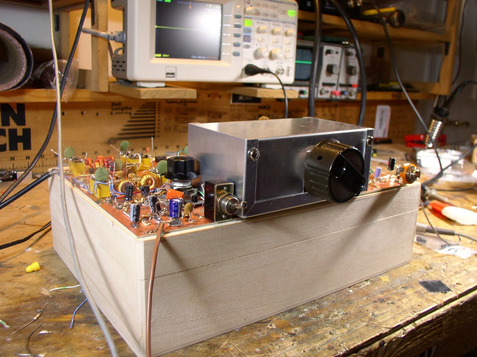
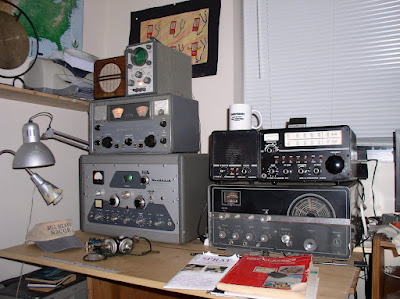
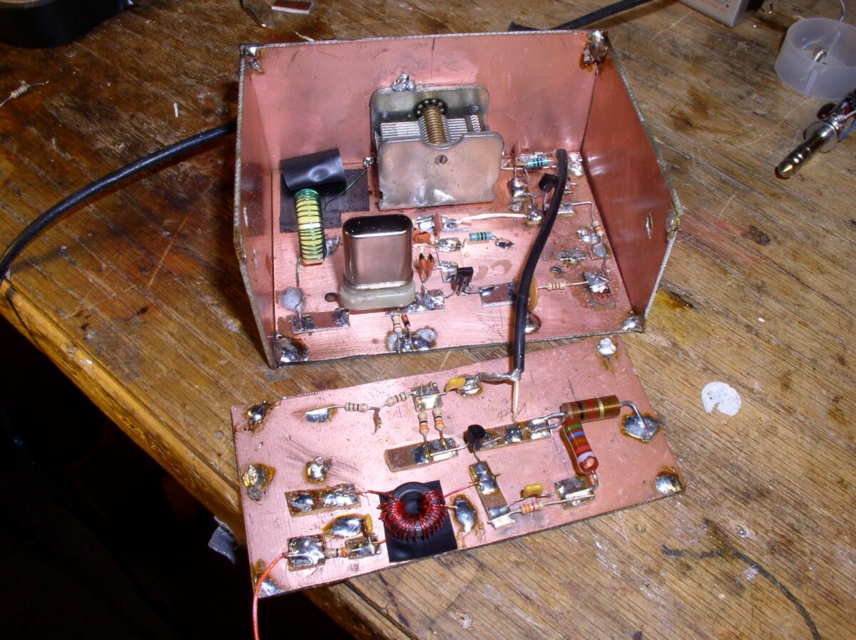
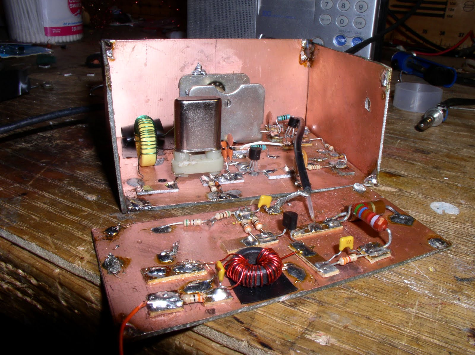
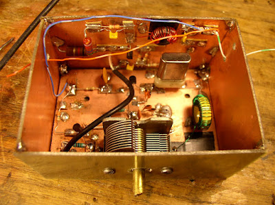
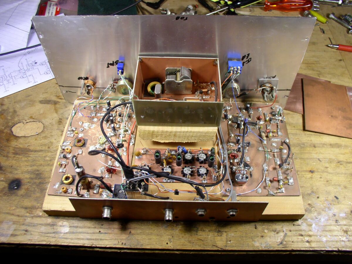
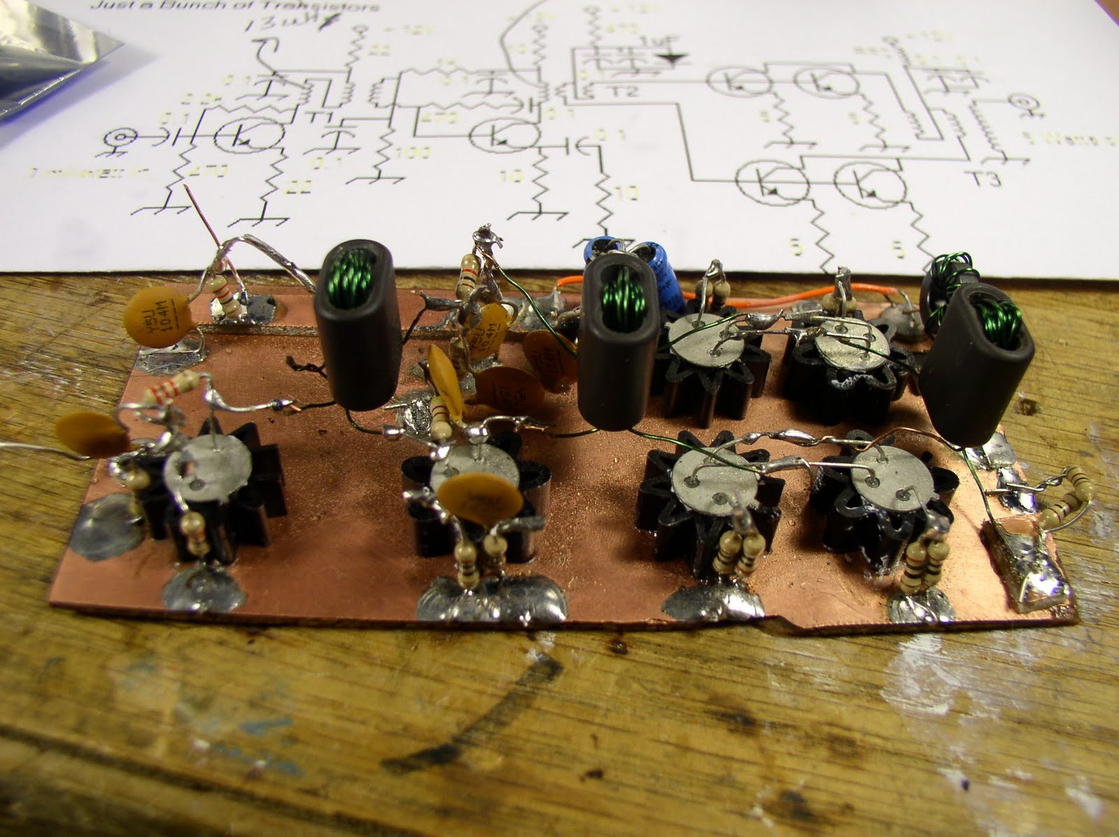
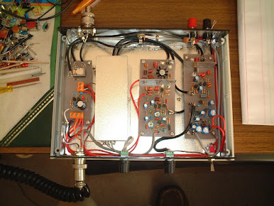
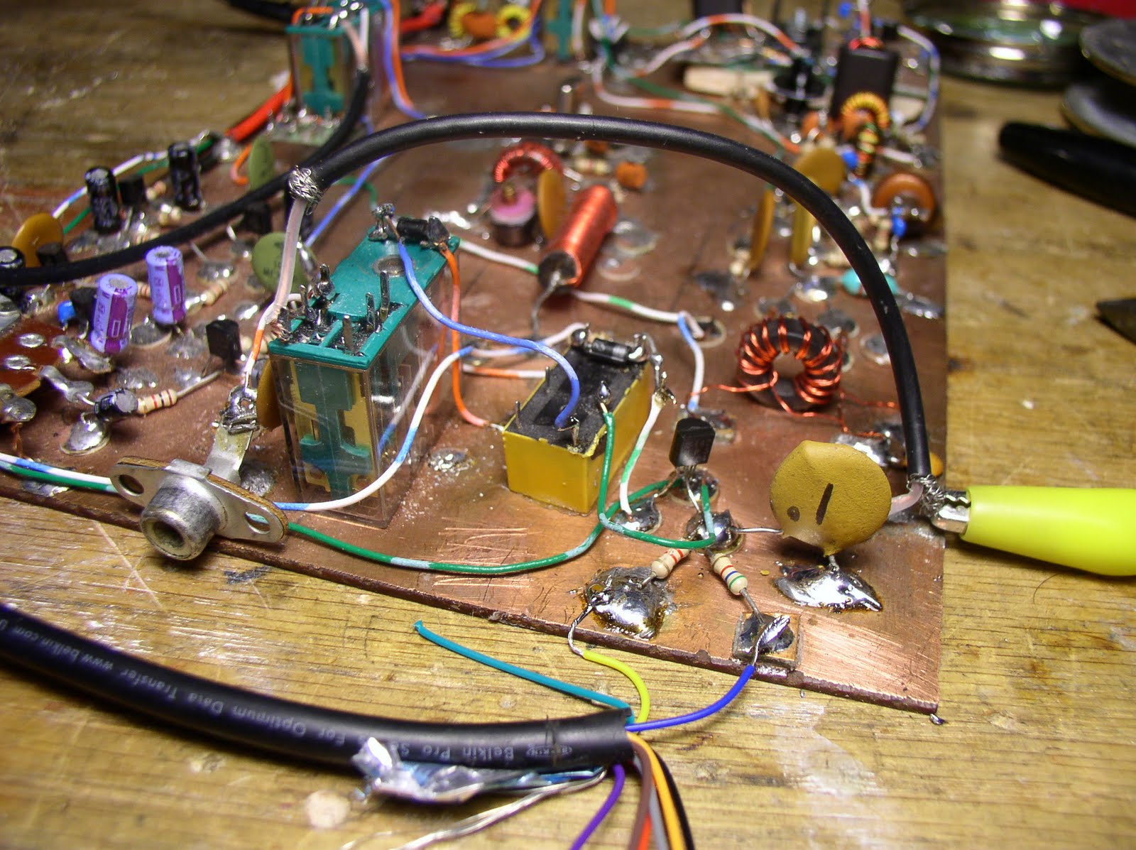
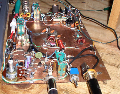
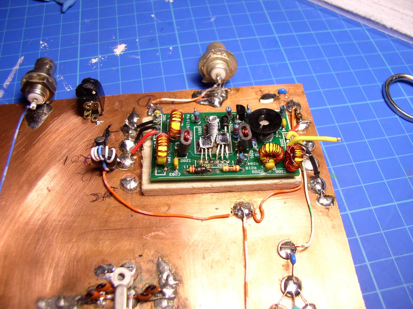
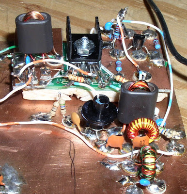
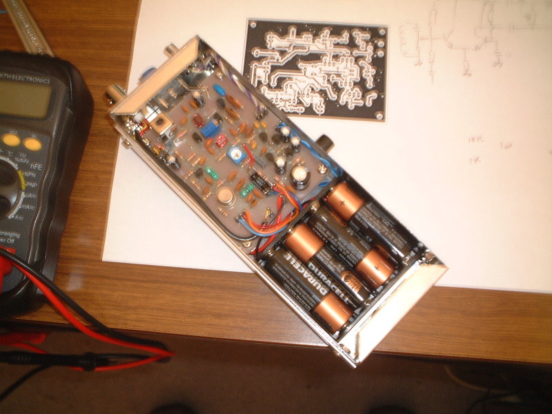
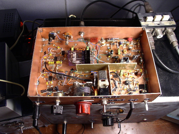
 I‘ve been remiss in posting to the blog, but I have a good excuse: I’ve been melting solder. I have working on the installation of my new Farhan-designed JBOT amplifier in my old Azorean DSB transceiver. I’m really enjoying this project, and I now see it as the first in a series. My shack has a number of creations that were built during the peak years of the last solar cycle, but have since fallen into disuse. Many of them were partially cannibalized — usually it was the RF amplifier that was taken out. The JBOT was just what I needed. I plan to refurbish all of these rigs, adding a bit of India to each one of them. This is very much in keeping with our “International Brotherhood of Electronic Wizards” ethos.


.JPG)