An Old but Cool DiFX: The Epiphyte


I’ve been hearing about this rig for many years. It first appeared in the September 1994 issue of QRPp, the journal of the NORCAL QRP club. A condensed version of that article appeared in SPRAT 81 (Winter 94-95). The designer is Derry Spittle VE7QK from Vancouver, British Columbia.

The name always puzzled me. Here is the explanation: It started with the Neophyte: A very simple direct conversion receiver that many of us built. The Neophyte was mostly an NE602 and an LM386. In the Epiphyte, a crystal filter and a second NE602 were added, turning the Neophytes into a superhet receiver and — with some additional circuitry — an SSB transceiver. The Oxford English Dictionary reportedly defines an Epiphyte as “a plant that grows on another plant”(see picture below). The Epiphyte grew out of the Neophyte.

And this plant grew in British Columbia, which seems — like Australia and New Zealand — to be fertile ground for simple phone rigs. I’m pretty sure the “Wee Willy” DSB rig also came out of BC, and it may have had a similar purpose: allowing for portable contact with the BC Public Service Net on 75 Meters.

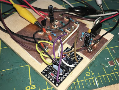
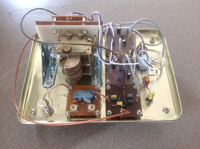
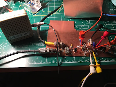
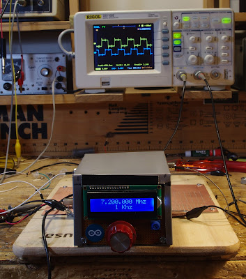
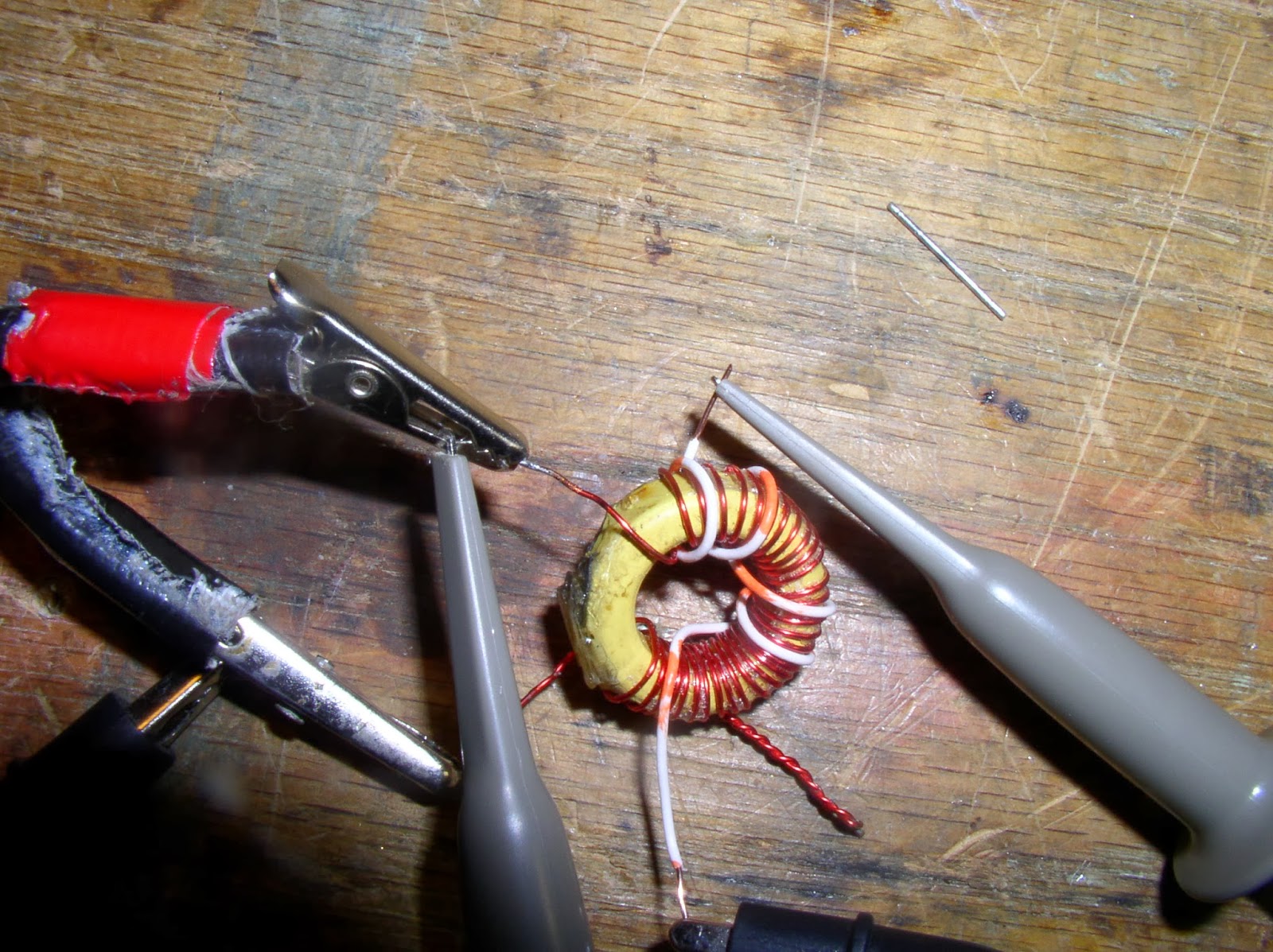
There are many features of the Epiphyte that I like: There is a simple 455 kHz filter and a ceramic resonator BFO/Carrier oscillator. The original design featured a VXO-like circuit using a ceramic resonator at 4.19 MHz. And it ran off AA batteries (as did the NE602 DSB rig I took to the Dominican Republic).

Unlike my NE602 rig, the Epiphyte made an artful use of the fact that NE602’s can be set up to have TWO inputs and TWO outputs. Where I used DPDT relays to switch inputs and outputs from both NE602s, OM Spittle left all the inputs and outputs connected, and simply switched the VFO and BFO signals. Ingenious.

There were updates and improvements. The Epiphyte 2 and 3 featured increased power out (5 watts vs. 1 Watt). Version 3 has an IRF-510 in the final, driven by a CA3020A chip. That chip is capable of 70 db gain. Wow.

In 1996 NORCAL and G-QRP donated 50 EP-2 kits to radio amateurs in third world countries. Very nice.

In 2000 NORCAL did a kit of the EP-3 — it sold out in 24 hours. Here is a nice article on the EP-3:
http://www.norcalqrp.org/files/Epiphyte3Mnl.pdf

And above we have a video from Japan of an EP-3 in action.


FB IBEW HB DC CW de UAE: A65DC’s International Homebrew Rig

Good evening!


After my JOO moment, Bill put me in contact with Pete Eaton, who suggested that I would have a look at the schematics for K4GC 40m CW Transceiver.
And I did, It was just perfect for me, low part count, lots of things done in software!!! Perfect Bryan!


I started off the build and both Bryan and Pete supported me along the way, thank you!

So here we have it:
The design slowly deviated further and further from the original, but I think I learned quite a lot by starting to make it “my own”.

The Arduino was changed to an UNO, yeah they are clunky and big, but I was not shooting for a pocket-size anyway… and they do have a proper USB port.
The RF-path is now switched by a relay straight after the filter, when the relay is relaxed the antenna is connected to the mixer, when I touch a paddle it connects to the TX circuit.
I have a short hang time from the last key input and it goes back to RX, VOX Delay I guess.

I completed the 700Hz bandpass filter, boy! this makes it a much nicer rig to work CW, I originally I skipped this filter for no good reason? That is the board standing up in the picture.
The TX circuit is a two stage, the first stage is a replica of VK3YE beach40 amplifier circuit, that also uses DB139. The second stage is a spin of the EMRFD Page 2.38 IRF511 Amp.
I have cranked it up to 17w, but it gets too hot too fast, as you can see I don’t have any proper cooling yet, I need to redo this board and plan for the heatsink a bit better.. it is now set around 10w, still getting hot, “599 TU 73”.
To be honest my CW does not go much further anyway, but I guess with this radio now completed I have one more reason to get my speed up.
I use for convenience both CLK0 and CLK1, when I go into TX I switch off CLK0 and do the keying on CLK1, both transmitter stages are powered up the whole time (until I stop keying as described above)

As the 700Hz filter worked so superb, I decided that I wanted to introduce “modes” to the rig, I can now switch the audio either thru the filters (CW) or straight to the AF amp (AM).
I do enjoy listening around, and we have a lot of AM stations on offer in my region.

I kept the smart RX mute transistor circuit and when I ask the Arduino to change mode, it will mute the receiver quickly, pull the relay and then un-mute again, no ear pain from the loud relay click. (I am happy with that detail).
The 2 line display became a four line, and I can change Tuning Rate, RIT, Key Speed and Mode by using only the encoder and the one button built into the encoder.
The front panel sports, on off, Headphones, Paddle and volume, the display and the big knob.
Power connector and USB Port on the side. I did complete the CAT control changes while working on this radio, it now uses the classic Kenwood interface e.g. TS480. (A lot fewer questions from the PC to answer.)

The CAT control works very nice while using N1MM, it works a lot less nice using CQRLog, I guess it has to do with the number of times the software in the PC is asking about things from the radio.
I will look into logic to only worry about incoming serial requests if I have not answered for some time, and never answer while in TX…

By pressing the VFO button a small arrow appears next to TR, if I push again it moves the arrow down to RIT and so on.
if I turn the knob with the arrow standing in front of e.g. KEY it will increase or decrease the KEY speed, when I press again, it will return to frequency control.

Oh, another detail (that I am happy with) while the arrow is in front of the KEY, you can fiddle with the paddle with out transmitting.. practical for testing the speed.

So this is a K4GC transceiver with bits and pieces from VK3YE and bits from the A65DC laboratory in Dubai, truly international.

To trim things in I scheduled a QSO with a local ham here, and things worked very nice, later the same night I made my first “DX” contact with RM2D!!! Moscow!!
What are the odds that a Swedish guy living in the UAE makes the first contact to another Swedish ham who lives in Russia!

73,
Martin A65DC

VK2EMU’s Biscuit-Tin Direct Conversion Receiver


Bill and Pete:
First Sound
The enclosure came first, then the radio. The Homebrew challenge – build something in a Christmas Biscuit tin – only one rule, no mains power.
Step one – eat the contents.
VK2WI is an Australian version of W1AW and transmits weekly new bulletins on a number of bands from 160m to 23cm. On 80m the frequency is 3595kHz, so let’s build a DC receiver for that.
I used a 7190kHz crystal, divided by 2 with a 74HC74 to get 3595kHz. The rest of the radio is pretty standard – double tuned front end, NE612 mixer, followed by a TL071 and a LM386. The reduction drive on the tuning cap gives a band spread of about +/- 300Hz.

The boards are all 2 inch x 2 inch and made on a PCB mill that I was given a few years ago.
There should be enough room in the bottom of the tin a pack of 8 C cells to make the radio truly portable. Next step is to fit an audio low pass filter.
It is a pleasure to sit on the rear porch and listen to the Sunday night broadcast on a home brewed radio, while eating the contents of another identical tin – I wonder what I will do with that one?

73 Peter VK2EMU


“First Light” on Brad’s Direct Conversion Receiver

So cool. You can just feel the enthusiasm. Congratulations Brad!

Bill and Pete:

After 63 years, I was finally able to build a DC receiver of my own design. We achieved “first light” at 7:20P last night. I attached the antenna, speaker, then applied power – and a all of a sudden “Bob’s your uncle!!” There are some things I still don’t quite understand but right now none of that matters as I listen to the sound of clean, crisp CW pouring out of the speaker and filling the room!! Major components – SI5351, SBL-1, TL072 op amp bandwidth filter, LM386 audio amp. I plan to use clk2 of the SI5351 with some Arduino code to create the companion transmitter and CW keyer. Life is good!!!
Brad WA8WDQ

N3FJZ’s New Blog and Impressive Rigs (and a Bandscan!)

Rick N3FJZ and his Lakeside direct conversion receiver bolstered my spirits when I was getting some harshly critical reviews of my signal on 40 meters a while back. Rick happened to pick me up with his homebrew receiver. The Radio Gods seemed to be trying to balance things out. There is a LOT of radio mojo in Rick’s Lakeside receiver. Not only does it eschew digital synthesis of the VFO signal, it goes a step further and uses a permeability tuned oscillator — very cool. The component and material sourcing adds more luster to the rig. Rick writes: “A lot of the components used to construct the LS-40 were harvested from discarded consumer electronics I collected back in the 1980’s. The base substrate material for the Manhattan style construction, as well as the RF tight enclosure for the PTO, is made from a flattened out tin plated food can. All components are discrete; i.e. no IC’s or CPU’s.”


Rick has launched a blog. He has some amazing stuff on it. Be sure to check out his ZX-SSB rig. Amazingly detailed documentation Rick! Thanks.

Find Rick’s Blog here:
http://www.remmepark.com/circuit6040/

New Rig: The FRANKENSTEIN Phasing Receiver

Here is my latest project. I call it The Frankenstein because of the two BNC connectors that come off the side of the DDS oscillator box — they look to me like the bolts on Frankenstein’s neck. The square waves from the DDS LO also seemed to evoke Frank’s bolts. There may be other similarities. We’ll see.

Here is the idea: Phasing, Direct Conversion, Image Rejecting receiver based largely on the R2 design by Rick Campbell KK7B as presented in the January 1993 QST.

I’m using an AD9850 with an M0XPD Kanga board and an Arduino to generate the quadrature LO signals (you can see the square waves on the ‘scope in the background). I’m using the software of Richard AD7C; this, combined with the divide-by-4 scheme on the Kanga board, puts the upper limit of reception at 7.3 MHz. That’s OK for now.

When I first fired up my AD9850 box I was dismayed to find that the square wave quadrature output was no longer there. I was about to give up and get anther shield board, but this kind of surrender bothered me. So I started troubleshooting and isolated the problem to the /4 chips. My soldering of the surface mount chips was, well, a bit dodgy, so I changed to a tiny soldering tip and reheated all those tiny little pads. Hooray! I fixed it.

The receiver will be built mostly on a PC board that Pete made for me back when he was trying to convince me to build a fourth BITX receiver. I am pleased to put the board to use. See below.

Yesterday I soldered on the two SBL-1 mixers that will form the heart of this receiver. I realized that the very robust quadrature square waves from the Kanga board might be robust enough to fry the sensitive little SBL-1s. Sure enough, I measured about 17 dbm coming out of the Kanga board. I threw together two roughly 10 db resistive pads. These should prevent the SBL-1s from releasing their smoke.

I hope this receiver will be four receivers in one:

1) Standard DC receiver.

2) Binaural Receiver! Groovy, stereo CW that floats around in your head, man!

3) I-Q receiver that can be fed into the sound card of the computer for DSP, panoramic display, etc. I promise not use it to find fault with the signals of homebrew SSB rigs.

4) SSB image rejecting receiver for easy, Direct Conversion SSB listening without the burden of having to listen to the other side of zero beat.

There is already a lot of soul in this new machine: Kanga board with the design my Paul M0XPD, PC board made on Pete’s $250,000 CNC machine, and all of it on an actual breadboard (from Italy, I think).

Rick Campbell and Peter Parker have commented on the allure of phasing rigs. There is something very attractive about them. There is a cleverness in the way this design exploits the phase relationships between sidebands to allow us to null out the unwanted side of zero beat. It took me a while to really understand how this is done — once I understood it, I really wanted to build a rig that would make use of this principle.

Bryan KV4ZS’s “Let’s Build Something” Direct Conversion Receiver

Bryan:
I think it sounds great! There is nothing really wrong with it — that is what 40 meters sounds like! Sure there is static. And those whistles you hear near the top of the band are the carriers from shortwave broadcast stations. You might have a little hum, but that should disappear once you get it all packaged in a metal box. Congratulations Bryan! You have done something that very few hams have done: You have built a receiver. 73 Bill N2CQR
………………….
Hi Bryan,
First let me congratulate you. That is one fine build and you may actually have absolutely nothing wrong!!!!!! I really must applaud your “squares”. They look like they were made on a CNC machine. Bravo!!!
You are operating the LBS without an RF amplifier and as such you are trying to make up the gain in the audio amp. I would say that the results you are hearing are very consistent with the DCR without an RF amp. Get the RF amps stage working and then run your test –you will find with the RF amp that at the gain setting you have for the video will be room filling. It actually sounds pretty good. You might also try connecting a 1 NF across the audio trimmer pot as that will cut down on the “hiss’ sound.
Concentrate on the RF amp stage and then re-run your test –you will see the difference.
Great build – very nice job.
73’s
Pete N6QW
………………..
Very nice!
Sounds pretty good to me in terms of noise – that’s what a direct conversion receiver sounds like (they tend to be very wide in terms of reception – static is normal… Welcome the world without noise reduction and DSP!!). DCR’s – because they are not run through a narrow IF filter – allow a very broad range of signals to get to the audio stage. So, for example, if you tune that around during a CW contest, you’ll hear a LOT of signals at the same time – versus only one or two at a time, once you have this run through the 4.9152 crystal filter. That’s the nature of the beast.
The 1nf across the audio trimmer definitely will help with reducing the hiss, although I must say my Kenwood receivers all have a similar amount of hiss and I prefer my radios with more, not less, noise (it lets me know what the band conditions are like…). I have noticed on my builds, however, that if you have a very, very high pitch WHINE on the other hand, that tends to be a bad solder joint or bad capacitor somewhere – probably on a capacitor – introducing an offset into your RF someplace it shouldn’t. What that looks like on an oscilloscope is the audio signal will have a large DC offset versus ground – almost always a bad solder joint on a capacitor—or a bad/broken capacitor–somewhere in the audio amplifier. That’s the same problem you get when you try to record audio sometimes from an external source (TV, radio, CD player) on your computer – DC voltage offset on the audio line. Kind of like what you might have heard on a stereo if you ever tried to switch to a channel where the input was hanging open.
Ben
KK6FUT

Peter Parker Reviews a DSB Kit and Presents Cool Mods (3 Videos). Also: Why DC Receivers Don’t Work with DSB sigs. (It doesn’t seem fair!)

I found Peter’s recording of the DSB signal being received by a DC receiver to be very interesting. We’ve long been warned about the very ironic incompatibility of DSB rigs and DC receivers.

In “W1FB’s Design Notebook,” Doug DeMaw wrote (p 171): It is important to be aware that two DSSC (DSB) transmitters and two DC receivers in a single communication channel are unsatisfactory. Either one is suitable, however, when used with a station that is equipped for SSB transmissions or reception. The lack of compatibility between two DSSC (DSB) transmitters and two DC receivers results from the transmitter producing both USB and LSB energy while the DC receiver responds to or copies both sidebands at the same time.” Bummer.

In essence, we’ve been warned that the simple DSB/DC rigs we’ve put on the air cannot communicate satisfactorily with similar rigs. We are, it seems, doomed to only speak with SSB/Superhet rigs.

The later portion of Peter’s second video allows us to hear just what happens when we try to listen to a DSB signal with a DC receiver: It sounds, well, unsatisfactory. I was trying to figure out why. Here are some ideas:

Simplify things by assuming we are transmitting only a single audio tone of 1000 Hz through our DSB transmitter. The rig’s VFO is at 7100 kHz. The 1 kHz tone results in signals at 7101 and 7099 kHz. Along comes somebody with a Direct Conversion receiver. If he were able to put (and keep) his receiver oscillator on EXACTLY 7100 kHz, he would end up (by taking the difference products from the product detector) with a 1 kHz tone resulting from the 7099 kHz signal AND a 1 kHz tone from the 7100 kHz signal. But there would be phase differences between these two signals, so you would end up with a less than pure 1kHz tone. (Did I get that right?) And if — as is likely — your local oscillator is a bit off frequency you’d get a real mess. If for example the local oscillator was at 7100.1 kHz, you’d have tones at 900 Hz (7100.1 – 7101) and 1.1 kHz (7100.1 – 7099). Yuck.

You might think you could just use the local oscillator in your DC receiver to replace the carrier in the DC receiver, turning it into an AM signal, then use an envelope detector as you would with any AM signal. But not so fast! For this to work your local oscillator would have to be not only at the same frequency as the original carrier, but also in the same phase. That is hard to do. (Hard, but possible — that is what they do with synchronous detectors using phase locked loops.)

I think you can actually hear many of the DC-DSB problems as Peter tries to tune in the DSB signal of VK7HKN using the DC receiver in the MDT transceiver. It is indeed unsatisfactory. But don’t worry. It is highly unlikely that when using a DSB rig you will encounter another DSB rig. I speak from experience on this. Pity.


Our book: “SolderSmoke — Global Adventures in Wireless Electronics” http://soldersmoke.com/book.htm Our coffee mugs, T-Shirts, bumper stickers: http://www.cafepress.com/SolderSmoke Our Book Store: http://astore.amazon.com/contracross-20

Pete and Ben’s “Let’s Build Something” Reference Page

Lots of tribal knowledge here! That’s the direct conversion receiver that forms phase 1 of Pete and Ben’s “Let’s Build Something” project. Arduinos! Si5351s! AD9850s! And it will morph into an SSB transceiver. Check it out:

http://www.jessystems.com/LBS_Detail.html

Our book: “SolderSmoke — Global Adventures in Wireless Electronics” http://soldersmoke.com/book.htm Our coffee mugs, T-Shirts, bumper stickers: http://www.cafepress.com/SolderSmoke Our Book Store: http://astore.amazon.com/contracross-20

SolderSmoke #171 DC RX in QQ, Power Supplies, Small Screens, 12 Buck Counters, HW8 Error?, KX3 RX

SolderSmoke Podcast #171 is available:

http://soldersmoke.com/soldersmoke171.mp3

Bench Report:
Pete’s Small Screens (in Color!)
Si5351s
Bill’s Graph Paper Frequency Readout
Bill’s Broadened Barebones Barbados RX. DIGITIZED!
Another AD9850 DDS using M0XPD Kanga UK Shield
New 13 dollar Color Display (Prettier than Graph paper!)

Pete and Ben’s Article in QRP Quarterly Available free here:
http://www.qrparci.org/qqsample/qqsample.pdf

The DEEP SPIRITUAL REWARDS of DC Receivers
The Importance of Good Power Supplies
SPRAT Article on HW8 Design Error
Latest Edition of Hot Iron
Elecraft KX3 — Has one of the best receivers in the world

Our book: “SolderSmoke — Global Adventures in Wireless Electronics” http://soldersmoke.com/book.htm Our coffee mugs, T-Shirts, bumper stickers: http://www.cafepress.com/SolderSmoke Our Book Store: http://astore.amazon.com/contracross-20

Pete and Ben’s “Let’s Build Something” Direct Conversion Receiver

This direct conversion receiver is part of the “Let’s Build Something” project of Pete N6QW and Ben KK6FUT. Publication will be in QRP Quarterly late in January 2015. Pete reports that the front panel is a piece of galvanized sheet metal from Home Depot –total cost 82 cents.

Our book: “SolderSmoke — Global Adventures in Wireless Electronics” http://soldersmoke.com/book.htm Our coffee mugs, T-Shirts, bumper stickers: http://www.cafepress.com/SolderSmoke Our Book Store: http://astore.amazon.com/contracross-20

Pete’s Boards Come Alive as a Direct Conversion Receiver (video)

I love it when a new rig is spread out on the workbench like this, pulling in its first signals. Like First Light on on a new telescope. These are the same boards you have been seeing in Pete’s previous videos: The Si board, the mixer, and the AF amp. Now they are linked together in the form of a Direct Conversion receiver.

Our book: “SolderSmoke — Global Adventures in Wireless Electronics” http://soldersmoke.com/book.htm Our coffee mugs, T-Shirts, bumper stickers: http://www.cafepress.com/SolderSmoke Our Book Store: http://astore.amazon.com/contracross-20

Pete’s “Let’s Build Something” Audio Amplifier (video)

Who needs LM386 ICs? Pete goes discrete! Love the MePads. And I knew Pete was going to test it with his finger! He’s just taking stray hum from the power lines and coupling it to the input through that Exacto knife.

Seems to me like these boards is getting close to actually receiving signals.

Our book: “SolderSmoke — Global Adventures in Wireless Electronics” http://soldersmoke.com/book.htm Our coffee mugs, T-Shirts, bumper stickers: http://www.cafepress.com/SolderSmoke Our Book Store: http://astore.amazon.com/contracross-20

Bert’s EMRFD Direct Conversion Receiver

Very nice Bert. Sounds great. I like the pill bottle coil core. Lew McCoy used them in his designs. I do think that air core coils do provide better stability than ferrites or iron powder. I kind of like the SW broadcast background music. I also like the internal 9V battery. Glad to see someone else resurrecting an old DC RX project.

Our book: “SolderSmoke — Global Adventures in Wireless Electronics” http://soldersmoke.com/book.htm Our coffee mugs, T-Shirts, bumper stickers: http://www.cafepress.com/SolderSmoke Our Book Store: http://astore.amazon.com/contracross-20

First Contact with Herring Aid 5 AND Tuna Tin 2

Ah, it was a good morning in the N2CQR shack! Last week I ran into fellow ham David Cowhig at work. I was regaling him with tales of Herring Aid and Tuna Tin derring-do. Oh the stations I had heard with the receiver! And the stations that I’d worked with the transmitter! Then David asked the question: “Yea, but have you worked anybody with the receiver paired up with the transmitter?” Uh, no. Not yet.
Well this morning I took care of that. 7040 kc. 1115 UTC. W4ELP was calling CQ. He wasn’t too strong, and I wasn’t sure if we were on the same side of zero beat (that’s what happens with direct conversion — you get all the sigs in two places on the dial) but I took a shot at it. And he heard me!
Here’s the icing on the cake: This was his SECOND QSO with my Tuna Tin 2! Ed had been contact #4 when I was running the TT2 with the Drake 2B. After exchanging reports he asked “Bill ARE YOU STILL ON THE TUNA TIN?”
The rig (TX AND RX) is pictured above. Close-up of the receiver appears below. And below that is a picture of Ed, W4ELP, in his Georgia shack. Note the HW-8.
Thanks Ed! Thanks David!


Our book: “SolderSmoke — Global Adventures in Wireless Electronics” http://soldersmoke.com/book.htm Our coffee mugs, T-Shirts, bumper stickers: http://www.cafepress.com/SolderSmoke Our Book Store: http://astore.amazon.com/contracross-20

Herring Aid 5: Working after 38 years!

I know, it is just a little Direct Conversion receiver. Getting it going is no great technical achievement. But this little receiver gave me such trouble as a teenager, it has been in the back of my mind for a long time. Finally, yesterday afternoon it started picking up signals.

I felt a bit bad about insinuating (a few days ago — see below) that QST may have made an error in the 1976 schematic. They didn’t. So it was kind of spooky when I heard that first call-sign coming through the speaker: It was W1AW! It was as if they were saying: “See, the schematic was correct!”

Our book: “SolderSmoke — Global Adventures in Wireless Electronics” http://soldersmoke.com/book.htm Our coffee mugs, T-Shirts, bumper stickers: http://www.cafepress.com/SolderSmoke Our Book Store: http://astore.amazon.com/contracross-20

Herring Aid: It was NOT the dots! Rotational Sense and Phasing

Opposite “sense” winding and resulting phase shift


My second attempt at building a Herring Aid 5 (the first was 1976) continues.

I thought I had discovered an error in the schematic that (I hoped) explained my failure to get this simple receiver running (scroll down for details). But Dex, ZL2DEX, in New Zealand spotted something that got QST off the hook and put all the blame back on me:

I had failed to check the rotational sense of the windings. The schematic called for 4 turns over the Radio Shack choke. So I just went ahead and wound them. I didn’t pay any attention to the direction of the winding. I then hooked it up in accordance with the phasing dots in the diagram. And it didn’t work. So I switched the coil connections around. And it worked. Aha! I thought! QST messed up! It wasn’t my fault.

Dex brought me back to reality. He noted that I probably wound the coils with the wrong rotational sense. I confirmed this. I rewound the coil following the rotational sense of the choke. I hooked it up following the phasing dots of the schematic. This time the oscillator started right up. So the problem wasn’t an incorrect drawing of the phasing dots. Instead it was my failure to remember that phasing is more than just the top or the bottom of a transformer’s winding. Rotational sense is also important. That’s why “phasing dots” are sometimes referred to as “sense dots.”

This doesn’t come up very often, because most of the toroidal transformers we make are bifilar or trifilar — the windings are always in the correct sense because we twist the wires together before putting them on the coil. When we look at those phasing dots, we are focused on getting the proper tops of coils connected to the appropriate bottoms of other windings. We don’t pay any attention to the sense of the windings. Thanks to Dex for bringing me back to my senses 😮

Grob’s Basic Electronics has this definition for those phasing dots:

Used on transformer windings to identify those leads having the same instantaneous polarity.”


This morning I did a little experiment to confirm all this: I took a toroidal core and wound a little transformer. Using a dual trace scope, I looked at the input and output wave forms. Sure enough, when the windings are in the same rotational sense, there is no phase shift. But when that secondary is wound in the opposite sense, you get a 180 degree phase shift. I know this is very basic, but it was fun to re-learn it and to confirm is.

But I still don’t have the little receiver running. I think there are a few problems. That single BJT mixer stage needs a lot of RF (2.5 volts p-p) from the oscillator. Also, I think the 10 uH chokes that I am using are not the same as the chokes used in the original Herring Aid design. So when I build transformers on these chokes, they don’t work very well.

But I will keep at it. It has been 38 years… I can wait another week or two.

Our book: “SolderSmoke — Global Adventures in Wireless Electronics” http://soldersmoke.com/book.htm Our coffee mugs, T-Shirts, bumper stickers: http://www.cafepress.com/SolderSmoke Our Book Store: http://astore.amazon.com/contracross-20