N8NM’s “20 Dollar Bill” DC Receiver

Steve N8NM wrote:

I call it “The $20 Bill” because it contains about $20 in junkbox parts and complies with Bill’s discreet component, hardware defined radio ethos.
73 – Steve N8NM


I replied:

Excellent Steve. Very nice.

Your post caused me to fire up my DC RX — I was listening on 40 earlier today. I think the world needs MORE 40 meter direct conversion receivers.


Too bad about the regulator IC chip. We need to get you an 8 volt Zener so that you can bring that receiver into a state of discrete component purity.

DISCRETE HDR FOREVER!


73 Bill N2CQR

Building the Ceramic Discrete Direct Conversion Receiver #4 — The Mixer

I think the most important stage of a direct conversion receiver is the mixer. This is the stage that takes the RF energy coming in from the antenna and — in one fell swoop — turns it into audio.

It is important to understand how this happens. I go into this in some detail in the SolderSmoke book. To summarize:

1) You have two signals going into a non-linear device. The way in which the smaller signal passes through the device — how much it is amplified or attenuated — depends on the instantaneous value of the larger signal. We are not just adding the two signals together.

2) The waveform that comes out will be a complicated repeating waveform. We know from Fourier that any complicated repeating waveform can be broken down into sine wave components.

3) When you analyze the complicated repeating waveforms coming out of the mixer, you will find that the sine wave components include a frequency that is the sum of the two inputs and another that is the difference between the two.

So lets suppose we have a non-linear device. We send in a signal from our oscillator at 7061 kHz. Coming in from the antenna we have a signal at 7060 kHz. The non-linear device will produce outputs at 14121 kHz (sum) and at 1 kHz (difference). We are interested in the difference frequency. We can HEAR that one. We feed it into our audio amplifiers and we can copy the Morse Code coming in. It will sound like a 1 kHz tone going on and off as the operator at the distant station presses his code key. (We don’t really have to worry about the 14121 kHz signal — it is easily eliminated by filters and would never make it through our audio amplifiers. And in any case we could not hear it.)

What can we use as a non-linear device? In this receiver we will use diodes. Diodes are extremely non-linear devices. They can be used as on-off switches, with one of the signals determining if they are on (conducting) or off (not conducting). When used like this they are “switching mixers.” In essence, a larger, controlling signal from the VFO will be turning the diodes on and off. Thus the signal coming in from the antenna will be chopped up by the switching action of the diode being turned on and off. This is non-linear mixing at its most extreme. It will definitely produce the sum and difference products we are looking for.

We could build the mixer with just one diode. You could apply the VFO signal to the diode to turn it on and off, and then feed the signal from the antenna into the same diode. You would get the sum and the difference product out the other end. You will see very simple direct conversion receivers intended for use in software defined radio schemes using just one diode. But this kind of circuit has a couple of serious shortcomingsq: it is susceptible to “AM breakthrough” and it is “lossy.”

The circuit we are using addresses these problems by using two diodes. To reduce loss, one conducts during half of the oscillator signal’s cycle, the other during the other half. Here LTSpice is ueful. You can model this mixer and see in the simulator how each of the diodes handles half of the oscillator RF cycle, with both contributing to the AF signal we want at the output (the difference frequency). (The schematic above is from LTSpice but it is not ready for simulation. For this you should replace the variable resistor with two fixed 500 ohm resistors, and add two oscillators — one with the weak incoming RF signal and the other the strong local oscillator signal.)

The AM breakthrough problem is also addressed by the use of two diodes. Here’s the problem: If you are on 40 meters, there will be strong shortwave AM broadcast signals coming in from your antenna. Some will be so strong that they will get past your front-end filtering. If you were using just one diode, that diode might demodulate the AM signal — the AM carrier would mix with the AM sidebands and you would have an undesired audio signal heading for your AF amplifiers. Many of us have experienced this — you are trying to listen to ham radio SSB signals, but you can hear China Radio International playing in the background.

The two diodes take care of this easily. Look at the way an AM signal would reach the diodes. The carrier (and its sidebands) going through the top diode will be 180 degrees our of phase with the signal going into the lower diode. But the output of the diodes are joined together. They will cancel out. We say that for the RF signal coming through from the antenna, the circuit is “balanced.” That signal — in this case the undesired AM signal — will cancel out at the junction of the two diodes.

But to understand this circuit you must see what is NOT cancelled out. The signal from the VFO is hitting each diode with the SAME polarity at the same time. Look at the 1k variable resistor. So the signal from the VFO will NOT be cancelled out at the output. Nor will the mixing products produced in the diodes. That last sentence is the key to all of this. The sum and difference products that result from the mixing of the signal from the antenna and the signal from the VFO SURVIVE. They are not cancelled out.

We can easily select the one we want. An RF bypass capacitor connected from the output of the mixer to ground will get rid of most of the VFO signal (7061 kHz) and most of the sum product (14121 kHz) while passing the audio to the AF amplifiers.

When I built this detector I used a trifilar toroid out of a box of them that Farhan left with me back in May. I used two of the windings secondary and one of the windings for the primary. You might want to make a more simple transformer using an FT-43 type core. I recommend W8DIZ as a source.

I hope this explanation helps, and I hope I got it right. Let me know if you see any errors in my explanation. Tinker with the circuit when you build it. You should be able to get it going.

Complete Schematic

Ceramic DC Receiver on the Cover of SPRAT. Happy New Year to All! Straight Key Night.

G-QRP very kindly put my little DC Receiver on the cover of issue Nr. 173. (Very sorry to see that GM3OXX has become a Silent Key. )

As we often say on the podcast, if you are not subscribing to this wonderful magazine, you are missing out on a lot of great ideas and circuits. Information on how to join the club and start receiving SPRAT can be found here: http://www.gqrp.com/join.htm It is only 22 bucks!

Reminder: Straight Key Night is upon us. It begins at midnight UTC 1 January. It is a great way to begin the new year. My HT-37 and my Drake 2-B are warming up now (and are helping to keep the shack warm on a very frigid day). HNY to all! 73 Bill


Building the Ceramic Discrete Direct Conversion Receiver – Part 3 — The Audio Amplifier

Once you have achieved JOVO and have the oscillator covering the frequency range you desire, it will be time to build the audio amplifier stage. Now, I’m sure many of you will be tempted to just throw an LM386 or 741 op amp in there. But don’t do that! You want to build the WHOLE receiver. Don’t let that IC manufacturer rob you of the FULL HB EXPERIENCE.

The DISCRETE amplifier circuit we will used is based on a design that several of us used to replace the LM386 in the BITX20 receiver.


And here is a tutorial that does a GREAT job of explaining how this circuit works. I strongly recommend you study the tutorial carefully. This site will allow you to really understand how your amplifier works.
It is not that complicated. But here you have to take care to make sure that your amplifier does not turn into an oscillator. Keep the outputs away from the inputs. Keep the leads short. Some planning is needed here. Click on the picture below for layout ideas. The right 1/3 of the board contains the AF amp circuitry.
After you build the circuit, TEST IT! If you have an AF signal source and a ‘scope, great. But if not, just hook some earbuds or headphones to the output, connect a 9 V battery and PLACE YOUR FINGER on the input of the first AF amplifier. If you hear a noticeable increase in hum when your finger makes contact, congratulations, your AF amplifier is amplifying.
The Complete Schematic

When you get this stage and the oscillator working, you are 3/4 of the way to completion. Next we will built the mixer, and then the front end filter and amplifier.

Building the Ceramic Direct Conversion Receiver Part 2 — Building the VFO — Our Goal is JOVO!

DC RX VFO and Buffer
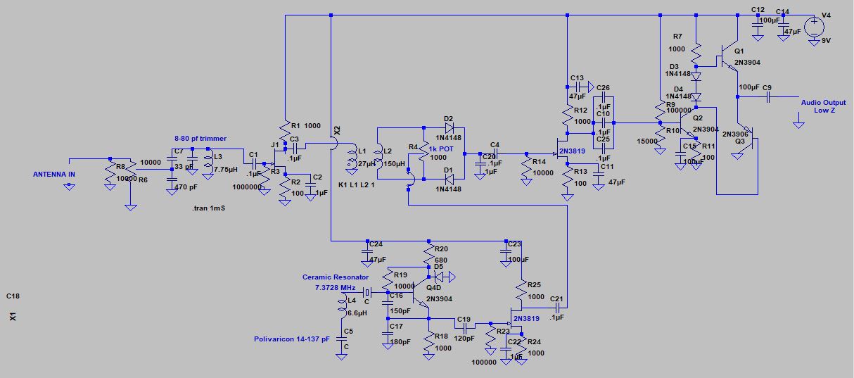
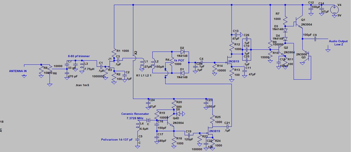
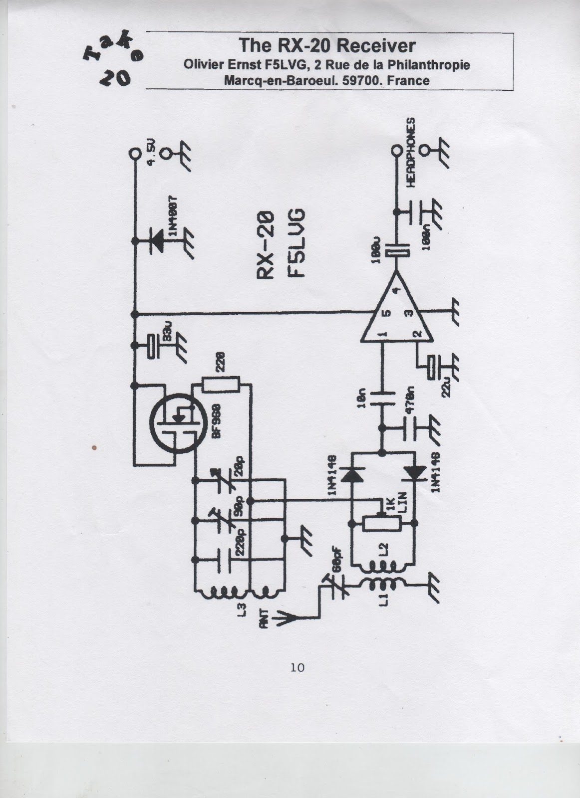
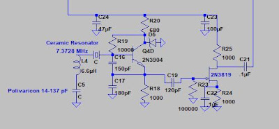
I’ll put the full schematic at the bottom of each of the posts so that you can easily refer to the big picture. Above you see the schematic of the VFO circuit.

OK, here we go. Let’s build the oscillator. Our goal is JOVO — the Joy Of Variable Oscillations.

At this point you should have a big-enough copper clad board, and you should have given at least some thought to what kind of enclosure you are going to put the board in when you are done. It pays to think ahead at least a bit, but don’t get so carried away with planning that you never get around to building.

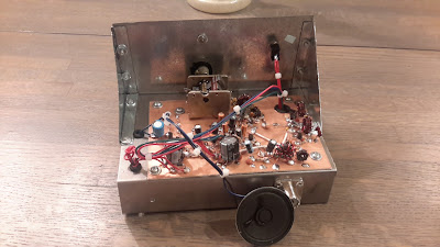
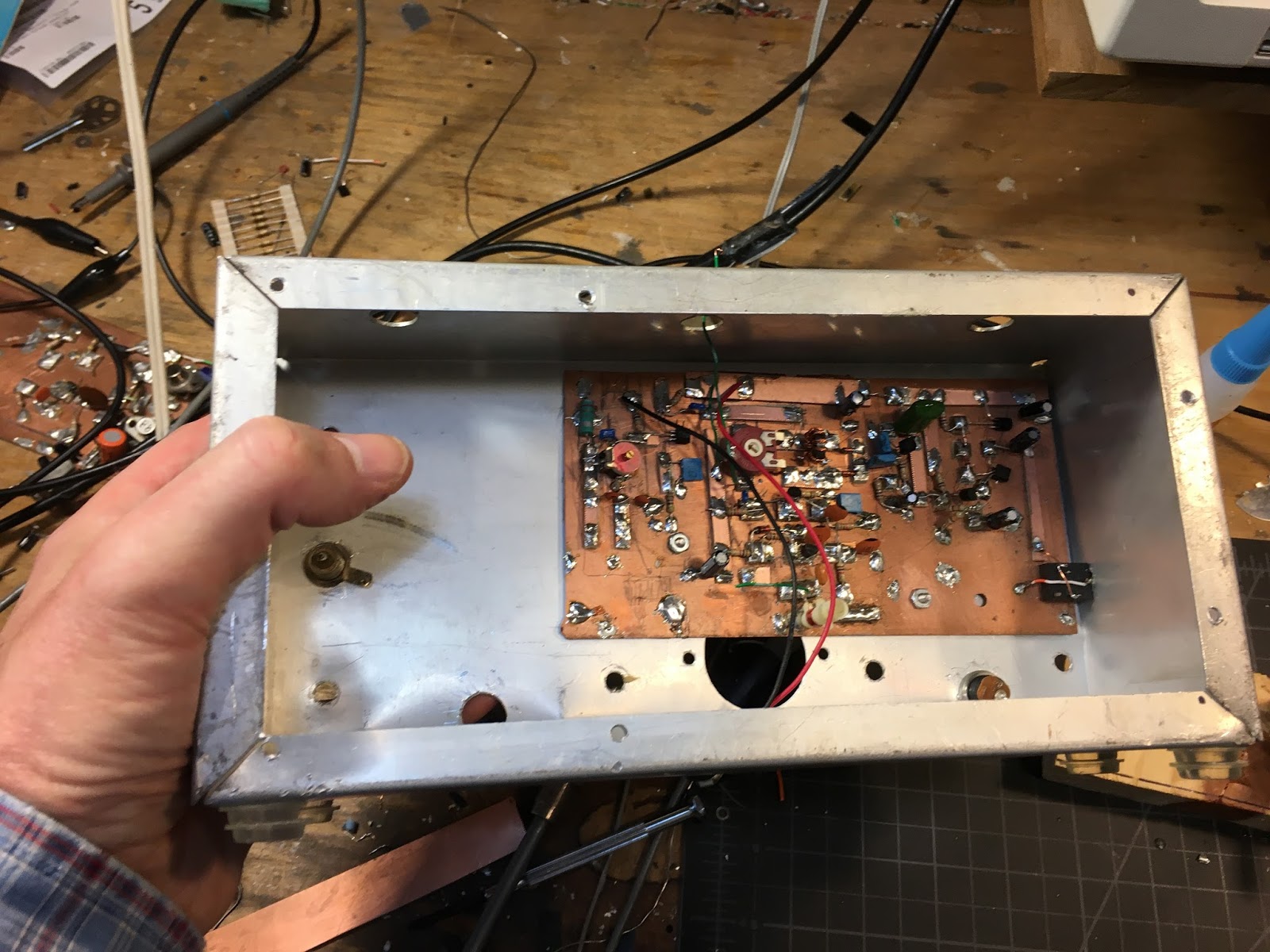
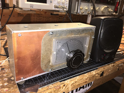
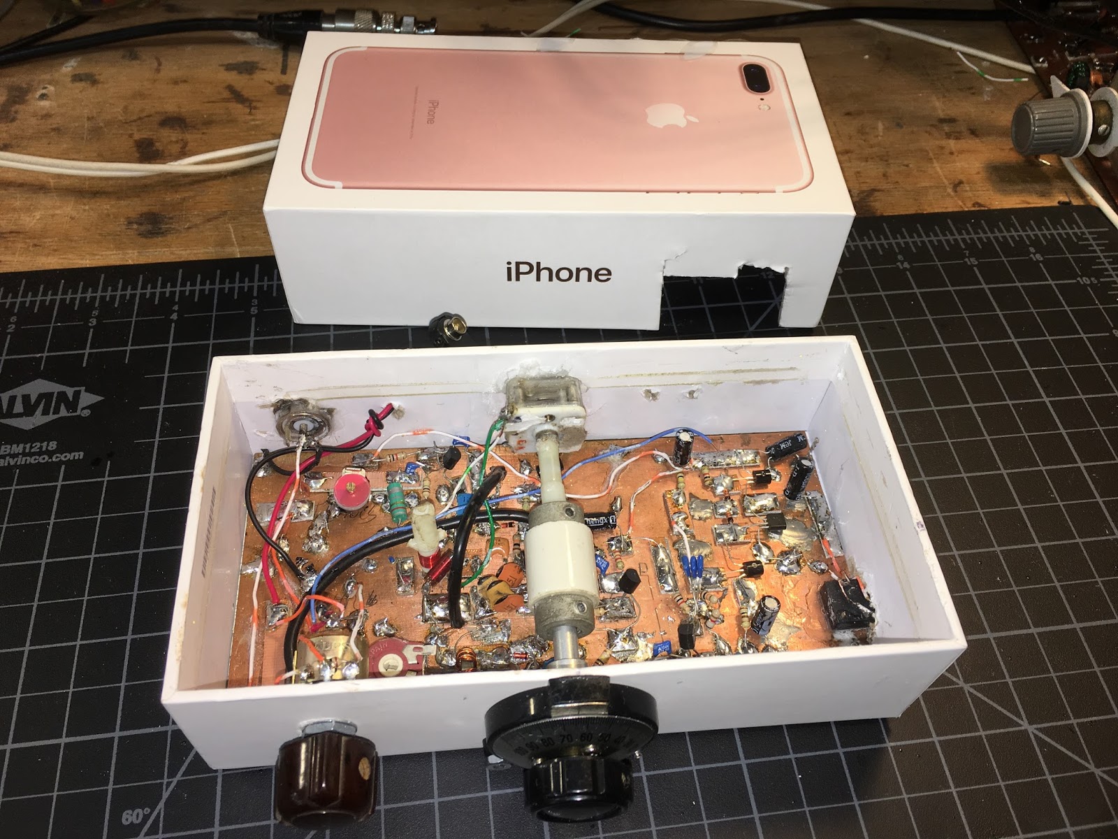
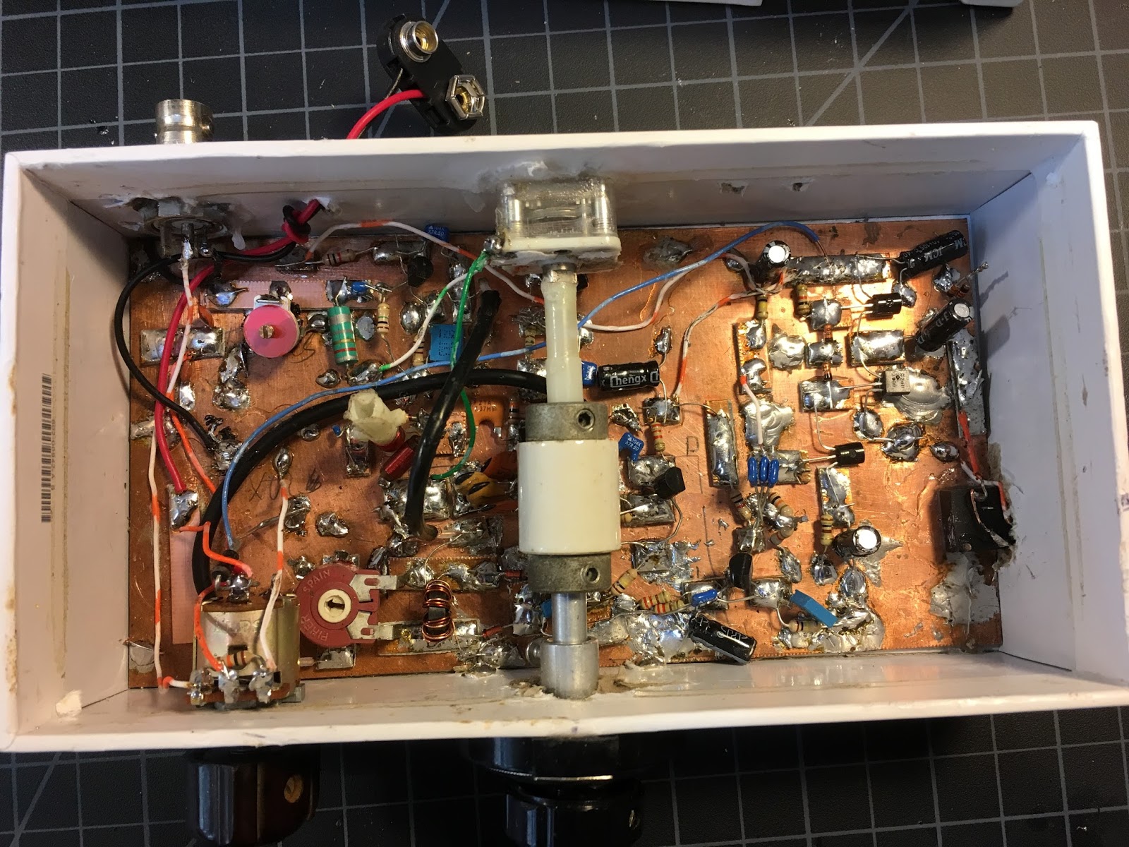
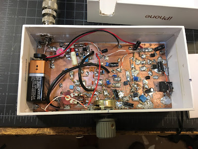
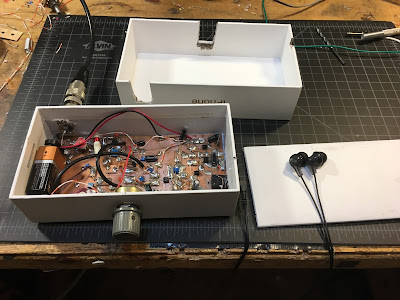
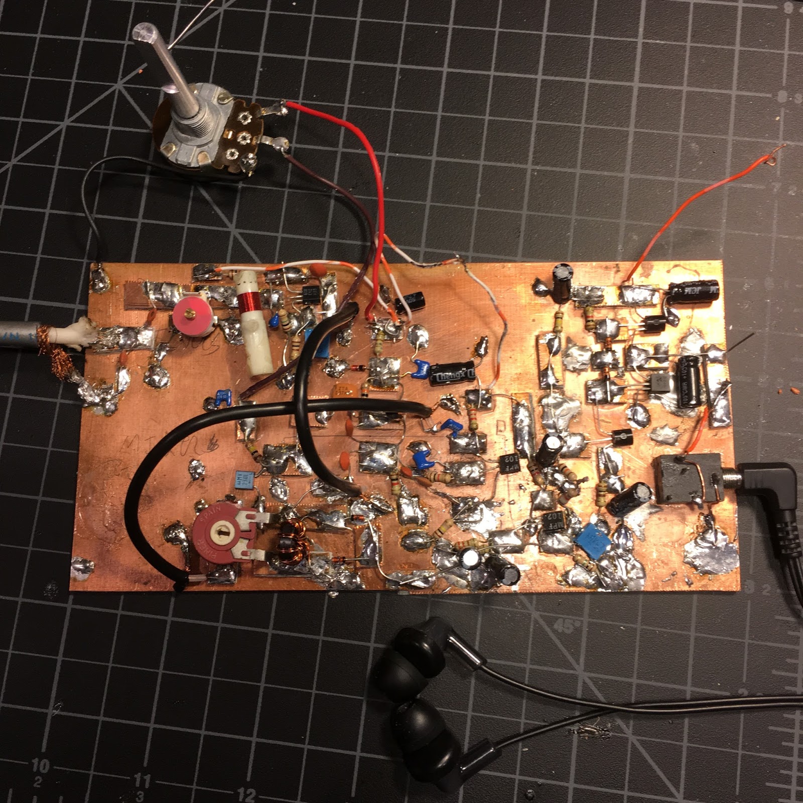
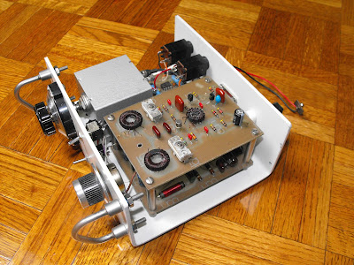
You should plan the allocation of the space on the board. Think about where you are going to place each stage. You can mark out the spaces with a pencil or a Sharpie marker. You might want to look at my board for ideas:

In the picture above you can see the four stages. On the left side of the copper-clad board you can see the Front end: the input filter and the RF amplifier (transistor near the top). Moving toward the center you can see the mixer stage (around the circular 1k trimmer potentiometer). Below the mixer (near the big round hole in the Bud Chassis) is the Variable Ceramic Oscillator stage and its buffer amplifier. The right 1/3 of the board is taken up by the audio amplifiers. Note the use of Manhattan pads throughout. Click on the picture for a closer look.


Once you know where you will put the VFO, eyeball the schematic and think about where you will need Manhattan pads. I often start by thinking of three rectangular pads for each transistor, one for each lead. You can see that there are a lot of parts hanging off each of the terminals. I sometimes put a long strip across the top or the middle of the board to carry the DC voltage.

Since this is an oscillator, you don’t have to worry too much about keeping the outputs away from the inputs. You want this one to take of on you.

For the feedback capacitors (C16 and C17) and the output capacitor (C19) , get some ceramic disc NPO caps. I put a 180 pf cap at C17 only becasue I didn’t have a second 150 pf cap in the junkbox. Either value will probably work.

You will need a ceramic resonator. I recommend this one from Mouser. Again, buy a bunch. They are cheap: https://www.mouser.com/productdetail/520-zta7.3728mt

You can, to start, build this circuit WITHOUT the two components that allow you to vary the frequency: without L4 and C5. Just run the left end of the ceramic resonator to ground. See below.

Connect a 9V battery to the top of C24. Without L4 and C5 (with one end of the resonator to ground) you should be oscillating at around 7.168 MHz (the capacitors in the oscillator circuit are pulling the frequency down from 7.37 MHz).

You need some way to find out if it is oscillating. If you have an oscilloscope, great. Put the probe at the output and take a look. But perhaps a simpler and more satisfying way to do this test is with a radio receiver. Tune the receiver around 7.168 MHz. You do not need to connect your receiver to the oscillator. You should be able to hear it. If you do, congratulations. If not, check your work. Be patient. This is not plug and play radio!

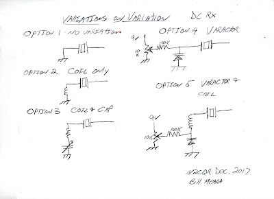
Once you get the thing oscillating, it is time to make it variable. Here is an opportunity for variety and experimentation. Here are some of the options you have:

Here is what I found. The frequency stability of these circuits vary. But all of them are stable enough. They might drift a bit so that you have to retune the dial every few minutes. If that realy bothers you you can upgrade to the air core coil with air variable cap arrangement.

When I put just a variable capacitor that goes from 17 pf to 159 pf between the ceraamic resonator and ground, I was able to tune the oscillator from 7.220 MHz to 7.420 MHz.

If I put a fixed 8.18 uH coil between the ceramic resonator to ground that moved the frequency to 7.010 MHz. You could use a toridal core coil for this, but I had best results with an air core coil. By putting the 17-159 pf variable cap between the coil and ground (similar to the arrangement shown above) I could tune from 7.010 MHz up to 7.367 MHz.

You could also replace the variable capacitor with a voltage variable capacitnce diode (aka a varactor or a varicap diode). I had good results with an MV2301.

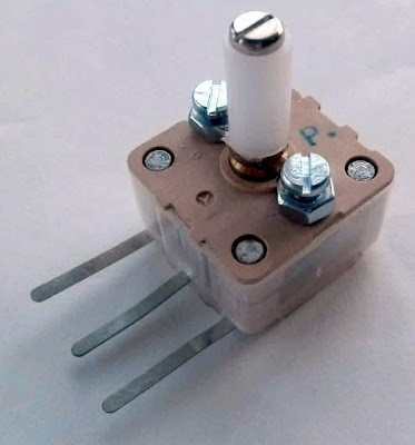
You could try using a cheap little polyvaricon capacitor for C5, but my best results came with an air variable. Walter KA4KXX points out that nice variable capacitors are available here:
https://www.amplifiedparts.com/products/capacitor-365pf-variable If you can, get one with a reduction drive to slow the rate of tuning as you turn the shaft. If you can’t get one of these, try to get find a reduction drive to slow down the tuning.

I ended up using a 3 uH air core coil with a variable cap of around 365 pf this allows me to tune from 7.115 MHz to 7.300 MHz (all of the phone portion of the band) with very good stability — Juliano Criteria levels of Stability.

One more idea: As you build this stage, or right after you finish it, go ahead and build a dulicate circuit, perhaps without the variation components. Why? Well that second oscillator might be useful when it comes time to peak and tweak the front end input filter of your receiver. And that second oscillator can become the start of a second version of this project.

We talked about this project in SolderSmoke Podcasts #199 #200 and #201

Now I’m going to the beach. I hope the holiday season bring you all joy — especially the Joy of Variable Oscillations. Send us reports on your progress, your joy, or your tales of woe.
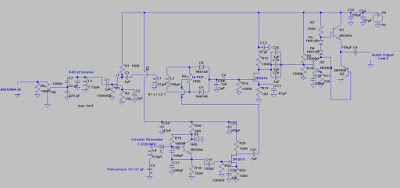
The Big Picture

SolderSmoke Podcast #201 Santa, Storms, BUILDING A DC RX, SDR, uBITX

SolderSmoke Podcast #201 is available: http://soldersmoke.com/soldersmoke201.mp3

9 December 2017

Santa Juliano

Forest fires, snow storms, and an earthquake.

Santa arrives from Hyderabad — uBITX in the house.

Radio history. First transtalantic amateur contacts.

Bill’s International Brotherhood Ceramic Discrete Direct Conversion Receiver Project.
— Goals — Build your own receiver. Really. From scratch. No cheating.
— How to get started. Get parts and tools.
— Stage by stage.
— VFO first — maybe build two.
Bill built two already
— Nephew is testing the first one.
— Polyvaricon limitations.
— Varactor limitations
— Variable cap limitation.
MEETING THE JULIANO STABILITY CRITERIA

Understanding the F5LVG mixer

Pete goes to the dark side with an SDR receiver.
Pete’s 800 Watt Amplifier gives him trouble. TRGHS.

People in the News
Cliff Stoll — Still Passionate about Electronics
Peter Parker — VHF/UHF By the Bay
Yardley Beers — Early SSB with “The Black Rose”
John Kraus — Moonbounce without the Moon.

MAILBAG


Discrete Ceramic 40 Meter Direct Conversion Receiver in Action (Video) — BUILD THIS THING!

I’ve been holding off on making this video until I improved the stability. N6QW is vigilent! I only did this video after certifying that it meets the Juliano Stability Criteria. I had to dispense with the polyvaricon and go with an air variable.

We will be talking about this on the SolderSmoke podcast next weekend. I hope to put on the blog a stage-by-stage discussion of how to build this receiver.

The dial from HI8P and the knob from a SW receiver that Elisa gave me definitely add soul to this new machine.

JOIN THE RANKS OF THE TRUE HOMEBREW RADO MAKERS! BUILD A RECEIVER! BUILD ONE OF THESE!

Videos of iPhone Box DC Receiver

These are just a couple of short videos that I made for my nephew before sending him this receiver.

As you can hear, deafness is not a problem with this design! I did make some frequency stability improvements after this video was made — I think you can hear a bit of drift. Still, not bad for a very simple circuit using a polyvaricon superglued to the back of a cardboard box.

I’ll post more videos of the second version of this receiver. There are further improvements in frequency stability. My goal: “Juliano Si5351” levels of stable-ness.

Polyvaricon Variations — Polyvaricons Are Not all The Same


When I built the first prototype of the iPhone DC receiver, I just reached into my junk box and used a polyvaricon capacitor for the main tuning control. It was marked PL 051. I was really pleasantly suprised at the stability of the Variable Ceramic Oscillator circuit. I could tune the entire 40 meter band with complete stability — Juliano levels of stability.


By the time I put the second version into its box (see above), I used a different polyvaricon (the one pictured below). It worked, but with this part the receiver drifted noticeably. So this morning I pulled it out and put in a second PL 051 Polyvaricon. Viola! Eccolo! Success. Drift eliminated. Rock stable.

Has anyone else noticed variations like this in the stabilty of polyvaricons?

The dial in this version is an Archer device that has been kicking around in my junkbox for more than 20 years. I think it was given to me by my old friend Pericles HI8P — this adds a tremendous amount of soul to this new machine). The box is an old Bud aluminum chassis. Man, this thing sounds great. I will try to post a video soon.

iPhone Direct Conversion Receiver with Variable Ceramic Oscillator

A while back Bob N7SUR got us talking about winter projects. Receivers. Of course, Pete and I quickly went down different paths. Pete is making great progress with lots of interesting digital circuitry. He is going over to the dark side. Check it out here:

I went with simplicity. Extreme simplicity. Direct Conversion (thanks Wes!). Discrete components. No chips. Analog Oscillator. 40 meters — monoband.

Schematic updated 29 November 2017
There it is. You can click on the picture to make it larger. Here is an outline of the circuitry:

— Single tuned circuit bandpass filter preceded by a simple pot that serves as a gain control.
— JFET RF amp
— Singly balanced passive mixer inspired by F5LVG’s RX-20 in SPRAT 100. For the coil I used one of the many trifilar toroids that Farhan gave me.
— The local oscillator is the coolest stage. I used a 7.37 MHz ceramic resonator and a circuit inspired by Miguel PY2OHH. With a polivaricon I can tune the entire 40 meter band. I put a reduction drive int here to make tuning easier.
— The AF amp is an op-amp free design. It works well into ear buds or into a computer speaker.
— Perhaps in an effort to catch the attention of the younger generation, I built it into an iPhone box.

Please let me know if you spot any flaws in the circuit, or see any places where it might be improved.

More to follow. This prototype is now in the mail, en route to my nephew John Henry who will be testing it for me.

SolderSmoke Podcast #200! 17, Knack Nobel, QCX, 630, UHF, Fessenden, TROUBLESHOOTING

DL3AO 1950

SolderSmoke Podcast #200 — TWO HUNDRED!!!!– Is available

http://soldersmoke.com/soldersmoke200.mp3

— Old friends on 17 meters.

— Another Knack Nobel in Physics.

— Hans Summers’ QCX transceiver: $50 IS THE NEW 10 GRAND!

— New Bands! 630 and 2200 Meters. BIG ANTENNAS!

— Nuke Powered QRP. No joke!

— The Challenge of UHF. Not for the faint of heart.

— Reginald Fessenden, Father of Phone.

PETE’S BENCH REPORT: The New Simple-ceiver. Soon to be a Transceiver.

BILL’s BENCH REPORT: Discrete, Direct Conversion, Ceramic Receiver in iPhone Box.

THE EDUCATIONAL PORTION OF TODAY’s PROGRAM:
HOW TO TROUBLESHOOT A HOMEBREW RECEIVER.

MAILBAG.

DL3AO 1950


A Direct Conversion iPhone!

Well, really a DC receiver in an iPhone box.

I think the Apple iPhone boxes have great potential as project enclosures. They are cardboard, but they are very rigid and solid. I decided to use them for a Direct Conversion receiver project I’ve had in mind.

This is a 40 meter DC receiver. No chips. Ceramic resonator VXO tuned by a varactor diode. 9V battery as the power source. Ear buds as the transducer. Passive, two diode, singly balanced detector. It sounds great — so great that I may have to add a gain control.

The nice fit is no coincidence — I cut the board so it would fit in the iPhone box.

Take a look at that top cover. It is all, well, empty. I could put another board in there, right? Maybe a balanced modulator, a mic amp and an RF amplifier. Then this thing would be a Double Sideband transceiver. We could even make use of the little microphone that comes with most of the ear buds.
I’m thinking that this might be the kind of project that people would like to take on this winter. Build the VXO first. Then the AF amp. Then the product detector and front end. At that point you’ve built a receiver. For extra credit you could go on to the transmitter. No need to use Apple boxes (but they are cool…) I will try to get the schematic done soon. My nephew John Henry will test the prototype.


The Homebrew Receivers of F5LVG

I came across OM F5LVG’s work in SPRAT. He has a wonderful website — it is in French, but Google Chrome translates is quite nicely.

http://oernst.f5lvg.free.fr/index.html

From the site’s introduction:

This site is dedicated to the construction and understanding of radio receivers. If you have dreamed of hearing a radio station with a receiver that you have built yourself, this site is for you. These are essentially direct conversion receivers and modern feedback detectors using only semiconductors, except for retrofitting. The described stations will accommodate amplitude modulation, single sideband (SSB) and telegraphy.

Besides these receivers several articles are devoted to LC oscillators. In particular, an extremely simple original stabilizing device is described.
Similarly, a simple frequency meter is described.
The joy of reception using a homebrew receiver is intense. May this site help you find this joy. Do not hesitate to join the amateur community.


TRGHS: I Can Hear the Roosters of Boa Vista

At the instigation of Bob N7SUR I’ve been working on a simple, easy-to-reproduce Direct Conversion receiver for 40 meters. I’m building this for my nephew John Henry, and I’m hoping this will be a circuit that others can use to break into the ELITE corp of successful ham receiver builders. Coincidentally Joh in Freiburg Germany is working on a very similar project — we have been comparing notes.

At first I used an FET detector described by Miguel PY2OHH. It worked, but at night the AM detection of powerful shortwave broadcast stations drowned out the amateur signals. So Joh and I started to explore detectors that would eliminate this problem. I went with a version of one described in SPRAT by F5LVG ( “The RX-20 Receiver”- see below). Very simple: A transformer to two back-to-back diodes with a 1K pot to balance the signal from the VFO. OM Olivier used a very, very cool transformer: he took two small, molded chokes and simply glued them together! 22uH choke as the primary, 100uH choke as the secondary. I went with one of the toroidal transformers that Farhan left me when he visited in May.

I’m using a varactor-controlled ceramic resonator VXO (no Si5351 in this one!) and a non-IC AF amp designed for use with ear buds (the world is awash in ear buds). It is a “singly balanced” design with the incoming RF signal being the one “balanced out” in the detector.

Last night the receiver passed the AM breakthrough test. The SW broadcast monsters were balanced out and kept at bay.

This morning the receiver passed The Boa Vista Rooster Detection Test. I fired up the receiver and heard an operator speaking Spanish with a Brazilian accent. When I heard the rooster crowing in the background I knew it was Helio PV8AL from Boa Vista Brazil. TRGHS — this little receiver is a winner.

I’ll try to post a schematic soon.

And hey — look at what wonderful IBEW (International Brotherhood of Electronic Wizards) project this is: Instigation and inspiration from Oregon. Some design ideas from Brazil. A French detector circuit described in a British QRP magazine. A transformer from India. A collaborator in Germany. And finally, the rooster of Boa Vista.

Let’s not forget Wes Hayward W7ZOI for bringing back (in 1968!) the neglected Direct Conversion idea.

SolderSmoke Podcast 199 Eclipse, Regen, BITX, DC RX, 3D OLEDS, Iphone Boxes, Mailbag

SolderSmoke Podcast #199 is available.

http://soldersmoke.com/soldersmoke199.mp3

2 September 2017

The Eclipse. The Floods.

Sawdust Regen gets John Henry off to a good start.
Voltage regulators as audio amplifiers

The return of the Simple-ceiver (Direct Conversion)

Ceramic Resonators

3D OLEDS

iPhone Boxes as rig enclosures

Electric Radio on Frank Jones

17 Meter Contacts

MAILBAG

The Return of Pete’s Simple-ceiver Plus (and a possible analog option)

Winter is approaching ladies and gentlemen, and it is time to think about radio projects. Bob N7SUR suggested a direct conversion receiver project. I think this is a great idea. As a kid, I had fallen victim to the idea that building receivers was “too hard” for radio amateurs. Not true! DC receivers to the rescue! Carry on with the DC revolution first launched by Wes W7ZOI in 1968.

Pete N6QW is providing guidance and tribal knowledge via his blog. For those of you who want to join the ranks of those who have defied the conventional wisdom and have broken through the “receivers are too hard” barrier. I say build yourself a DC receiver. Build it from scratch. Many of you already got your feet wet in homebrewing with the Michigan Mighty Mite project. Now it is time to jump into a DC receiver project.

You folks already know what kind of VFO Pete will prefer: It will be an Si5351. That’s fine. But I will try to keep the banner of discrete component analog ludite-ism flying high. This morning I ordered a batch of 7.37 MHz ceramic resonators. I hope to pull them down into a significant portion of the 40 meter phone band. If this works, I will share the batch with anyone who wants to joining my Analog Army (remember the CBLA?). Note (above) that Pete has magnanimously left open the possibility of using a non-digital VFO. What a guy!

Check out Pete’s project here:

http://n6qw.blogspot.com/2017/08/a-new-line-of-transceivers-difx_19.html

“So You Want To Build?” Words of Wisdom from Pete Juliano


Everything on Pete’s blog is worth reading, but this article was so good that I could not resist posting a link to it here.

Tribal knowledge from a leader of the homebrew tribe:

http://n6qw.blogspot.com/2017/08/a-new-line-of-transceivers-difx.html

Straight Key QRP Homebrew Adventures — TRGHS

Last Saturday I put the Tuna Tin Two Top together with my Herring Aid Five 38 (year) Special and the Indian key that Farhan gave me. I discovered that some of my 40 meter CW FT243 crystals had disappeared into the entropy of the shack. But I was able to find one for 7050 kHz. That was a bit of good luck because it turns out that 7050 is the frequency of a congenial group of operators known as the Straight Key Century Club. I felt right at home. I have been inducted. My SKCC number is 17272. Very QRP, don’t you think? It is almost a Vanity SKCC. Clearly, TRGHS.

I have been having excellent luck with this 7 transistor rig. I have had one contact each day since I put it on the air, all of them in response to my CQ calls. I’ve worked:

K1PUG Hank in Connecticut (twice)
W8HOG Jerry in Ohio
WA4GQG Kevin in North Carolina
WA2AAW Frank in New York
KM4FO Dwight in Kentucky


This morning I added a little piezo buzzer for sidetone. I am thinking of adding a VFO to the Tuna Tin.

More “Canned Seafood” Homebrew CW, from KA4IBG

Bill:

My xYL hates sardines, but they look good together !
In the late 70’s the community had a fetish for canned seafood and DC receivers. Do you remember the 80m Sardine Sender ? How about YL Special ? (QST Oct and Jan 1979.) I married them together in a kludged-together box made out of a bent rack-mount panel and defunct aluminum chassis cover.
The bottom board is the rock-bound transmitter. The upper deck is the receiver board. The little mini box contains VFO (so cute.) The 741 audio board is tucked under the scrounged ¼ inch jacks.

Super simple, but lots of fun. It’s a handy rig for the week at the beach, although 80m propagation and beach week are 6 months out of phase.
Ed Hlywa
KA4IBG