Amazingly Cool MONTV Video on Direct Conversion Receivers with Glue Stick PTOs

I think this is one of Nick’s best videos. And he has made a lot of good ones.


This is a really excellent description of how a Direct Conversion receiver works. But more importantly Nick really captures the joy of building one of these receivers using discrete, analog components, including a Permeability Tuned Oscillator made from our beloved Glue Sticks.

Extra mojo comes in the form of a mixer designed by Pete Juliano using J310s to simulate a 40673 dual gate MOSFET. Fantastic. Icing on the cake comes from a W8DIZ AF amp out of SPRAT magazine.

There is a grand finale. I won’t spoil it. Watch the video. Suffice it to say that Farhan would be pleased with this.

Great stuff. Thanks Nick!

A Treasure Trove of Permeability Tuned Oscillator (PTO) Info and Links (Plus Info on Direct Conversion Receivers)

There is really great info on this page, and even more in the links at the bottom of it. While the page is about PTOs, the links often discuss their use in Direct Conversion Receivers. I really liked the Tin Ear receiver. And it was great to again come across the work of Alan Yates VK2ZAY. Alan very admirably admits that laziness caused him to use an LM386 audio amplifier in place of a more virtuous discrete transistor design.

https://qrpbuilder.com/pto_mechanism

I bought one of the qrpbuilder PTO kits and I will soon put it together. I have been having good results with a Glue Stick PTO and with a brass screw PTO form designed by Farhan and 3D printed for me by Dean KK4DAS.

LET’S GO PTO!

Direct Conversion Receiver — Simple 2-Diode Mixer Defeats Radio Marti, but Diode Ring is the Best

Here is another update on Direct Conversion receiver construction. In Northern Virginia we get very strong signals from the Radio Marti transmitter in Greenville NC. During the morning hours it is just above the 40 meter band at 7335 kHz. In the evening it is a bit higher in frequency at 7435 KHz. (in the video above I mistakenly give the morning frequency, when in fact they were on the higher evening frequency). In either case, Radio Marti has been a big source of unwanted AM breakthrough in our simple DC receivers. It now serves as something of a test of our bandpass filters and mixers.

In this video I try out the simple mixer described in detail here: https://soldersmoke.blogspot.com/2022…

The following morning, I tested the mixer with Radio Marti (in fact) on 7335 kHz. By adjusting the VFO signal input to the minimum value needed to turn on the diodes, I was able to bring Radio Marti AM breakthrough to minimal levels. But I could still hear it (weakly) in the background. Putting a very simple diplexer at the audio output of the mixer (just a .1uF capacitor in series with a 47 ohm resistor to ground) helped a lot.

I could also hear break through from Spanish-language broadcasts from Vatican Radio on 7305 kHz (using the 250 kW transmitter in Greenville NC) from 11:30-11:45. Perhaps most surprisingly, I was also getting AM breakthrough from 40 meter FT8!

Here is a short video showing the simple two-diode mixer in action during the morning hours:

I also tried out the more common two diode mixer with trifilar toroid. (In this one, the VFO turns both diodes on, then turns both of them off). The results were similar to what I got with the other two diode mixer.

We are trying to develop four circuits — bandpass filter, mixer, variable frequency oscillator, and audio amplifier — that will be simple enough for construction by high school students, but not so simple as to compromise performance. We want the receiver to work well.


So far, my conclusion is that the best results come from the diode rig mixer with two trifilar toroids. Here is a short video showing the diode ring in action on the morning of November 9, 2022:

Understanding a Very Simple Two-Diode Mixer

Take a look at the simple little mixer above. I think I first saw it in SPRAT. Thinking that it was really just a simplified version of the two diode Doug DeMaw mixer that I had been using for years, I couple of years ago I built it into a little Direct Conversion receiver. It worked great. But later, I began to have doubts about it. In the words of young James Clerk Maxwell, I started to wonder about “the particular go of it.”

You see, the way the DeMaw mixer is set up, both of the diodes are simultaneously on and off. This has the effect of “chopping up” the incoming RF at a rate set by the VFO frequency. Boom. Fournier. Mixing. Great.
But look at the mixer at the top of this post. Here the VFO signal is coming in on the wiper of the 1k pot. The same signal is hitting both diodes at the same time. The diodes are not being fed differentially. So D1 and D2 are NOT both simultaneously tuning on and off. Instead, when the wiper goes positive, D2 turns on while D1 is off. On negative swings of the voltage at the wiper, D1 turns on while D2 is off. For me, this made it a “mystery mixer.”

This reminded me of the sub-harmonic DC receiver I built earlier in the year: The VFO runs at half the operating frequency, but the diodes are set up to switch on and sample the RF TWICE each VFO cycle. This is the equivalent of having the VFO at the operating frequency.
Could it be that this was just a sub-harmonic mixer with the VFO at the operating frequency? (I should note that Doug DeMaw published a design that actually made this mistake. See: https://soldersmoke.blogspot.com/2011/07/doug-demay-and-polyakov.html ) I knew that this would sort of work, but it would not work very well. And the mystery mixer seemed to work very well. Hmmm.

I was loaning the DC receiver with the mystery mixer in it to a local high school. I worried that I was loaning them something that I didn’t really understand. I remembered that I’d been trying to figure out this mixer since early 2021: https://soldersmoke.blogspot.com/2021/02/some-thoughts-on-singly-balanced-mixers.html

Our beloved book, Solid State Design for the Radio Amateur (SSDRA) has an explanation of this circuit on page 74. But this explanation didn’t seen to work for me. Check it out. YMMV.

Bottom line: I still couldn’t figure this circuit out, so left it alone for while.

The other day I woke up and looked at it with fresh eyes. Suddenly it hit me. Although the VFO was hitting the diodes in the same non-differential way as is done in the sub-harmonic mixer, the RF (signal) is entering the mixer in a differential way. This means that the two diodes are taking turns sampling the upper side of L2, then bottom side of L2, via L1 and L2. This results in a complex repeating waveform that is similar to that of diode ring mixer. Within that complex repeating waveform, there are sum and difference frequencies. I did some noodling on this:

The key difference between this mixer and the sub-harmonic mixer is the way L2 is positioned: In the sub-harmonic mixer, there is no differential feed of the RF. Both diodes get the same polarity of RF. The VFO switches on D1, then D2. The RF is sampled at twice the VFO frequency. But in the mystery mixer that had me scratching my head, the RF is fed to the diodes in differential form. So while the diodes here are — as in the sub-harmonic mixer — being switched on and off sequentially, they are taking turns sampling the top and the bottom of L2. That provides the complex repeating waveform that we need to get the sum and difference frequencies. In a DC receiver the difference frequency is audio.

What do you guys think? Do I have this right? How would you characterize this mixer: Is it multiplying by 1 and 0? Or is it multiplying by 1 and -1?


This would be good mixer for a school project. It is simpler than a mixer with a tri-filar toroid.

SolderSmoke Podcast #241 Mars, Direct Conversion, PTOs and Glue Sticks, Anniversary of the BITX20, Multus Proficio SDR, Boatanchor Station, MAILBAG

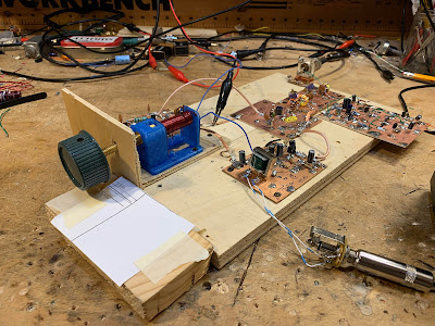
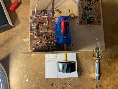
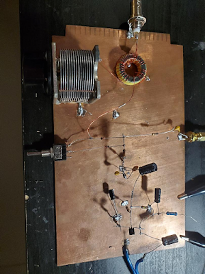
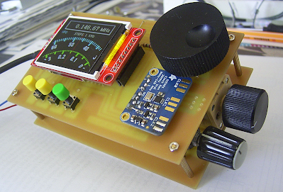
The board I use to test DC RX circuits

SolderSmoke Podcast #241 is available

Audio (podcast): http://soldersmoke.com/soldersmoke241.mp3

Video (YouTube): (215) SolderSmoke Podcast #241 October 28, 2022 – YouTube

Introduction:

Back on Mars. Opposition approaching. I have a Mars filter. And (like T.O.M.) a Mars globe.

N2CQR DXCC done

SolderSmoke in the WayBack Machine

Sticker news

PARTS CANDY — Don’t Scrimp with a Crimp!

Bill’s Bench

School DC RX projects — in Hyderabad and Northern Virginia.

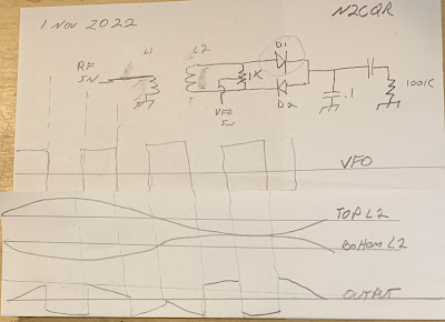
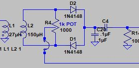
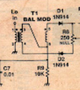
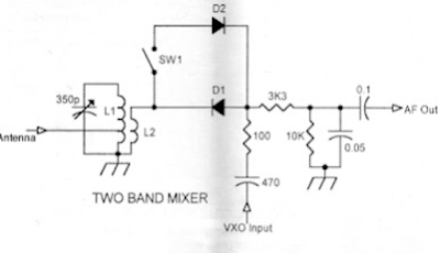
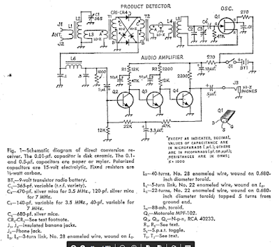
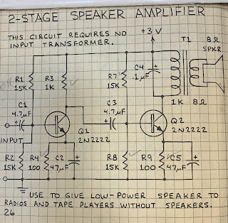
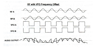
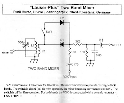
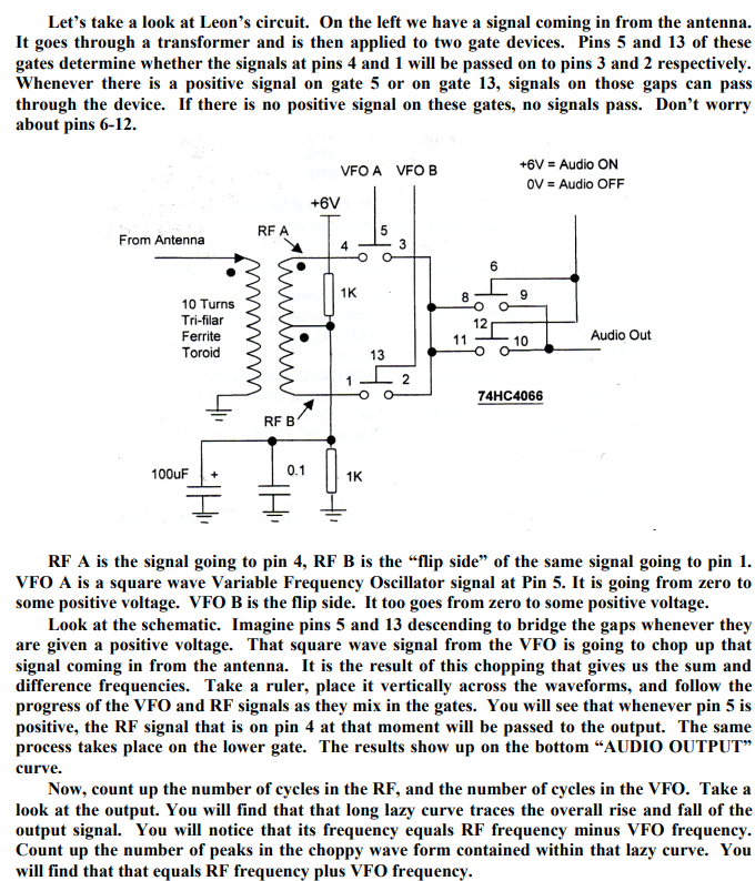
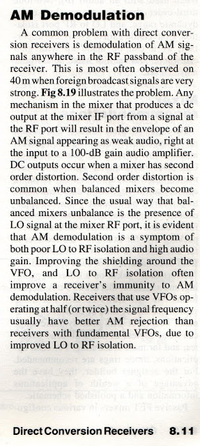
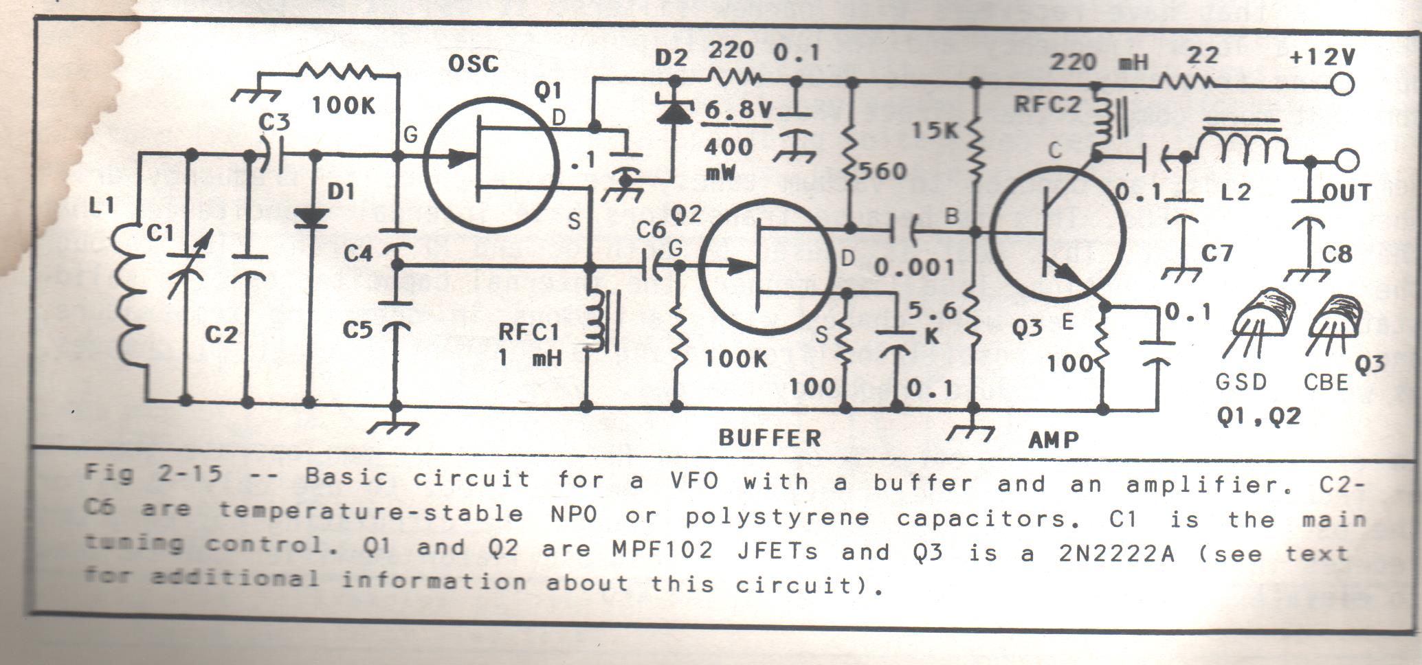
Direct Conversion Receivers — Keeping it Simple, Learning a Lot. A step beyond the Michigan Mighty Mite. Do we really need 100db? Do we really need to shield VFOs? Farhan’s super-simple and stable Colpitts PTO. Audio amps, 1000-8 transformers and rolling your own LM386

PTOs and Glue Stick PTOs. Paul Clark WA1MAC. Brass vs. Steel bolts. #20 thread vs. #28 thread. Backlash Blues. The best Glue Sticks.

2 meters and the VWS. Bill has a Baofeng.

SHAMELESS COMMERCE: MOSTLY DIY RF

Pete’s Bench

20th Anniversary of the BITX20 Pete’s early BITX rigs.

Computer Woes

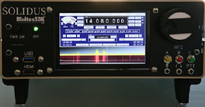
The Multus Proficio SDR rig

Simple SSB in China BA7LNN

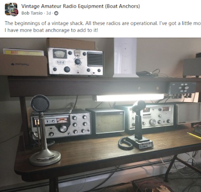
Things of beauty: Tempo One, NCX-3 and a SBE-33

MAILBAG

— NS7V is listening.

— Graham G3MFJ sent SPRAT on a stick.

— Nick M0NTV FB Glue Stick and 17 Shelf videos.

— Dino KL0S HP8640 Junior

— Mark AA7TA Read the SolderSmoke Book

— Steve EI5DD Connaught (Ireland) Regional News

— Dave K8WPE Planting the seeds of ham radio interest

— Peter VK3YE Ruler idea on PTO frequency readout

— Michael AG5VG Glue Stick PTO

— Tobias A polymath with UK and Italy connections. And cool tattoos.

— Alain F4EIT French DC receiver

— Michael S. was in USMC, working on PCM/TDM gear

— Alan Yates writes up Amazon transformer problem

— Todd VE7BPO, Dale W4OP, Wes W7ZOI

— Farhan VU2ESE sent me an sBITX

— Todd K7TFC The Revenge of Analog

— Jim Olds Building QRP HB gear


The Multus SDR rig Pete discussed

The older rigs Pete mentioned


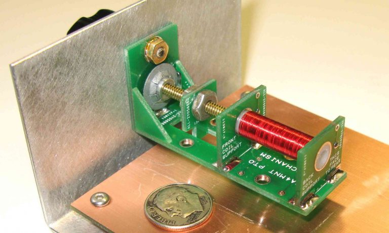
My version of DC RX that Farhan is working on

My PTO with VK3YE’s ruler frequency readout


DC Receiver: 100db Gain? Diplexer? VFO in a box?

Here is a progress report on Direct Conversion Receiver developments. Dual Tuned Circuit, Diode Ring with Diplexer, PTO VFO from Farhan’s Daylight rig, two stage 49 db BJT AF amp with a transformer. It works very well. I discuss: Shielding of the VFO — necessary or not? Why brass in the PTO? Do we really need 100db in a receiver, especially with ear buds? Sourcing the AF amplifier’s transformer. Using W7EL’s diplexer. (I think it has solved my Radio Marti breakthrough problem). Developing a DC RX circuit that can be built by students. I end with a bandsweep of 40 meters that includes CW, FT-8, SSB, and AM

How the Diode Ring Multiplies by 1 and -1 — “The Secrets of the Diode Ring” — Plus another Bandsweep with the DC RX

A deeper look into how the Diode Ring detector works: “the particular go of it.” Here I rely on a wonderful diagram from the RSGB. This diagram clearly shows how in this circuit, the switching action of the diodes — controlled by the VFO — results in sum and difference frequencies at the output. This is amazingly illuminating. I then tried to build this actual circuit. It works, but I am also getting a lot of AM breakthrough from a local AM station (WFAX) and Radio Marti at 7335 kHz. I will try again. In any case, the diagram shows how the diode ring does its thing! I need to beef up the Band Pass Filter. I tuned around a bit on 40 meters — you can listen. Students at a local high school have been trying to get the DC receiver I loaned to them going — they may be confused by the intricacies of SSB tuning. I will see them next week.

Here is the RSGB diagram that reveals the secrets of the Diode Ring. (Now that could be the title of a book or movie. I claim the rights to that!) Click on the image for a better view.

Adding a Diode Ring to the Direct Conversion Receiver, And How the Diode Ring Works

I take a look back at Wes Hayward’s classic DC receiver from the November 1968 QST.
I then try to describe how diode ring mixers work (“the particular go of it”) using Alan Wolke’s excellent YouTube description as my base.

I present some drawings that I did that use the “crossed diode” diagram as the start.

I also discuss interference from Radio Marti’s 250 kW transmitter on 7335 kHz in Greenville NC.

Finally, we listen to the receiver a bit.

Alan Wolke’s Diagram
Wes Hayward’s 1968 DC Receiver

Update on the Direct Conversion Receiver — Now only 4 transistors

I took a new look at the receiver, did some measurements, and decided to take out the RF amplifier and the AF pre-amp. The receiver works fine without them, another indication that they were unnecessary. Line-up is now: Band-pass filter, Mixer, VFO, AF amp. I think there is only 49 db of gain in the entire receiver, but it is useable with an un-amplified speaker, and is a bit too loud on ear buds. Not bad for just 4 transistors. And I think we could do this with just 3 (no need for the VFO buffer).

Here is the AF amplifier I used:

Bandsweep with the New Homebrew 40 meter Direct Conversion Receiver

It is inhaling nicely but some improvements are still pending. Click on the video above to see and listen to the bandsweep done on 40 this morning.

— The front end consists of capacitive divider input impedance matching circuit, followed by one LC circuit and an FET RF amp.

— The VFO is a super-simple Colpitts design by Farhan. The two feedback capacitors do double duty in the LC tan circuit.

— I am using an old variable capacitor instead of the PTOs that we have been experimenting with.

— The mixer is singly balanced using one trifilar toroid and two diodes. We have found out that even with these three simple devices, there is significant variation in how people connect them to VFO, RF in and audio out. I think we have found the best way to do this: Be sure to put the VFO on the primary of the transformer, and let this signal turn the diodes on and off.

— For the AF amplification, I have one FET, followed by two BJTs. I have a small audio transformer between the speaker and the final AF amp. There is plenty of audio.

You may wonder why, after all the SSB superhet transceivers, I am building a simple Direct Conversion receiver. Well, we hope to help a bunch of high school kids build one, so we need to be really familiar with how it works. And I find that as simple as it is, there is still a lot to learn in a project like this.

A Bout of Direct Conversion-ism in Northern Virginia — DC Receivers Under Construction

There I was, minding my own business, when suddenly I was dragged into the construction of Direct Conversion receivers.

Here is a video about my latest effort. But I feel the urge for more simplification — I may go back to the seminal DC receiver designed by Wes W7ZOI and presented in the November 1968 issue of QST. It is on page 15 here: https://worldradiohistory.com/Archive-DX/QST/60s/QST-1968-11.pdf

Michael AG5VG Builds a Sub-Harmonic Receiver and Moves it to Higher Bands

Michael AG5VG built a Sub-Harmonic Direct Conversion receiver. But then he took it a step further and moved it up from the 80/40 meter version that I had built, and used the same concept to run it on 20 meters using an oscillator on 40 meters (after some re-winding of the front-end coils). Using a station from Puerto Rico transmitting on 20 meters as an example, he starts out showing how well the receiver works in sub-harmonic mode (with the oscillator on 40), then quickly switches to normal Direct Conversion mode with the oscillator also on 20 (but using only one diode as the detector) — he can still hear the Puerto Rican station in that mode. Very cool.

Good Evening Bill,

I built the Polykov and I attached a picture of it. I also used Pete’s pre audio driver circuit from his jessystems.com site. Then I used an lm386 as the main audio driver. I could hear ft8 on the 40m band. Then I hooked the output of my lm386 circuit to a conventional set of computer speakers to really hear it. I am currently using an indoor wire antenna along the ground so it’s certainly not optimal. Very fun build and I’ll be learning more about it. When I have a better antenna system I’ll hook it all up and send a video of it.

73s
MIchael
AG5VG


Bill,


I am just using a standard signal generator at 1 vpp output. The volume gets louder with every 100 millivolt I go up, but so does the noise. 0.8vpp was a little low for me so I bumped it up a bit.

The indoor antenna actually did surprising well but I’m looking forward to putting a wire up into a tree I have here. I just recently moved so I have to setup my outside antenna. I live in the San Antonio, TX area.

I am currently using three stages of audio amplification to be able to really hear it. 1st stage is Pete’s pre audio driver, then an lm386, then a standard set of computer speakers.

I did plenty of playing around with it last night and the doubling function is so cool how it works. When I was around 3.538 MHz, with the variable cap tuned for the 7Mhz area, I was actually listening to 7.76Mhz, the FT8 frequency for 40 meters. I agree with You and Pete in a podcast you did a bit ago, that FT8 is great for seeing if the band is open and checking receivers with!

The next project is the art of the 3.5 – 4Mhz analog VFO and use it with the Polykov. I am very dependent on the Arduino/Si5351 pair as the code is available and easy to hook up.

Will keep you both updated.

73s
Michael
AG5VG

Two more videos from Michael:

Testing

Operation
I think this is a great example of good experimenting. Michael took the concept, made some mods, and put the device on another band. FB.

SDR on a Breadboard — But Isn’t This an Old-Fashioned Fantasy?

Nice video, but I’m afraid it is a bit of an old-fashioned fantasy. It would be nice to think that our beloved analog mixers and direct conversion receivers still have a place in the SDR world. That may have been true a few years ago when we were using soundcard-based SDRs. But today we just put an Analog to Digital Converter at the antenna, do “Direct Sampling,” create a digital stream, and sent it to the CPU for processing, right?

Sometimes we think that we can show younger people how our older tech (Direct Conversion receivers) is STILL relevant in the age of SDR radio. But I can just hear them scoffing at this notion, pointing out that I,Q-to-soundcard front ends have gone the way of the dinosaurs, and all we need now is an ADC and a CPU.

But hey, I am an HDR guy. Am I missing something here?

Vasily Ivanenko on Vladimir Polyakov’s Subharmonic Detector

Our old friend “Vasily” sent in a very insightful comment about the Polyakov receiver. It was so good that it merits a blog post of its own. Here it is. Thanks Vasily!

Vasily IvanenkoAugust 9, 2022 at 12:49 AM

Thanks Bill. My own experiments at HF with subharmonically pumped Schottky diode mixers show clearly that almost every mixer parameter we measure is worse than our classic balanced mixer topologies. Definitely 2LO-RF isolation was better than other unbalanced mixers without the need for a transformer.

I guess it’s appealing for low-complexity receiver builders. For zero IF receivers, I like and run my LO at 1/2 RF frequency and then use a doubler — that’s a great advantage for
a DC/ Zero-IF receiver and a built-in feature for the subharmonic mixer.

The SH mixer becomes quite appealing at SHF to mm-wave lengths where making a quiet, temp stable LO gets rather expensive and tricky.

Subharmonically pumped mixers can also work at odd integers if the mixer LO/RF drive is balanced and designed to produce distortion that for example, triples the LO frequency. Rohde & Schwarz had a 40.1 GHz spectrum analyzer with one — and if the LO was 13 GHz while the RF was 39.5 GHz, this gave an IF output of 500 MHz in 1 particular circuit. Really amazing design work. Here’s an interesting URL:

https://www.eravant.com/products/mixers/subharmonically-pumped-mixers

The SH mixer has been around for > 4 decades. The oldest SH mixer paper I’ve got in my library is from Schneider and Snell from 1975. I don’t think they invented the SH, but this pair helped popularize it for the world and design work continues today.I’ve seen optical SH mixers with I/Q outputs in research papers.

Here’s the abstract and citation:

Harmonically Pumped Stripline Down-Converter

M. V. Schneider, W. W. Snell
Published 1 March 1975
Physics, Engineering
IEEE Transactions on Microwave Theory and Techniques

A novel thin-film down-converter which is pumped at a submultiple of the local-oscillator frequency has given a conversion loss which is comparable to the performance of conventional balanced mixers. The converter consists of two stripline filters and two Schottky-barrier diodes which are shunt mounted in a strip transmission line. The conversion loss measured at a signal frequency of 3.5 GHz is 3.2 dB for a pump frequency of 1.7 GHz and 4.9 dB for a pump frequency of 0.85 GHz. The circuit looks attractive for use at millimeter-wave frequencies where stable pump sources with low FM noise are not readily available.

Best to you!

Polyakov Direct Conversion Receiver on 80 Meters (video)

In today’s episode I put the switch in the open position turning the receiver into an ordinary Direct Conversion receiver with a single diode as the detector. I find that it works pretty well on 80, but probably not as well as it does on 40 (where it is in full Polyakov mode). (Yesterday I demonstrated the receiver in action on 40 and provided details on the circuit. See: https://soldersmoke.blogspot.com/2022/08/polyakov-ra3aae-direct-conversion.html)

You will notice that when I throw the switch, but before I retune the input LC network, you can still hear the signal from the previous band. So when I have it in 40 and I throw the switch to open, you can still hear the 40 meter signal. Apparently one diode will (poorly) demodulate a signal with the VFO running at HALF the operating frequency. I saw this in the real world receiver and also saw it in an LTSpice simulation. In LTSpice the signal level drops significantly when I go to just one diode: From 50 mv peak to 15 mv peak, but it can still be heard. Something similar happens when I go from 80 to 40. When I close the switch and suddenly have two diodes and a 3.5 MHz VFO trying to demodulate the 80 meter signal, I can still hear the 80 meter signal, but it is much weaker and a lot more noise is getting through. Again, I saw this in the real world and in LTSpice. It looks as if with the two diodes, the 3.5 MHz signal is being sampled twice each VFO cycle. This may result in some output in the audio range. But again, it is much weaker.

Polyakov (RA3AAE) Direct Conversion Receiver: 40 meter DC RX with VFO at 3.5 – 3.6 MHz (with video)

I’ve been reading about Polyakov (or “sub-harmonic”) Detectors for a long time:

https://soldersmoke.blogspot.com/search/label/Polyakov–Vladimir

But until now, I never built one. Recently, Dean KK4DAS and the Vienna Wireless Makers group have been building a Direct Conversion receiver. Their receiver uses an Si5351 as the VFO, but of course Dean and I have decided to try to do things the hard way by building non-digital VFOs. At first we just came to the conclusion that my earlier Ceramic Resonator VFO wasn’t much good (it drifted too much). This led us into standard Colpitts and Armstrong VFOs, and the fascinating world of temperature compensation. Then I remembered the Polyakov circuit — this would allow us to use a 3.5 MHz VFO on the 7 MHz band. Lower frequency VFOs are easier to stabilize, so I started building my first Polyakov receiver. You can see the results (on 40 meters) in the video above.

I started working with a circuit from SPRAT 110 (Spring 2002). Rudi Burse DK2RS built a Polyakov receiver for 80 and 40 that he called the Lauser Plus. (Lauser means “young rascal” or “imp” in German.) For the AF amplifier, I just attached one of those cheap LM386 boards that you can get on the internet. With it, I sometimes use some old Iphone headphones, or an amplified computer speaker.

The Polyakov mixer is a “switching mixer.” The book excerpt below shows how I understand these circuits. The enlightenment came from the Summer 1999 issue of SPRAT (click on the excerpt for an easier read):

Leon’s circuit shows us how a simple switching circuit in which the switches are controlled by the VFO can result in an output that has the sum and difference components. That is the hallmark (and most useful part) of real mixing. Remember — we say that mixing happens in non-linear circuits when the passage of one signal depends on what is happening with the other signal. A switch is as non-linear as you can get! And that switch is being controlled by the VFO.


In a Direct Conversion receiver we usually run the VFO at the operating frequency. This results in audio just above and just below the operating frequency.

The Polyakov Direct Conversion circuit is a bit different. It has the switches (the diodes) turned on twice each cycle: When the VFO voltage goes to a positive peak, this turns on one of the diodes. When the VFO goes to a negative peak, this turns on the other diode. So in effect the switch is being turned on TWICE each cycle. So with the Polyakov you run the VFO at HALF the operating frequency. For a DC receiver designed to run around 7.060 MHz, you build a VFO at around 3.53 MHz. This has some immediate advantages. My favorite is that it is easier to get a VFO stable at a lower frequency. It is easier to stabilize a VFO at 3.53 MHz than it is at 7.060 MHz.

When you open that SW 1 switch in the Lauser Plus, you no longer have a Polyakov mixer. Now you just have a diode mixer. It will be opening and closing once each cycle at the VFO frequency. DK2RS used this to cover not only the 40 meter band (in Polyakov mode) but also the 80 meter band (in single diode detector mode). That is why DK2RS has that big variable capacitor in the input circuit — that LC circuit needs to tune all the way down to 3.5 MHz and all the way up to around 7.3 MHz. (I used a coil of about 6.5 uH to do this.)

With just one diode and operating at 80 meters, it works, but not as well as it does in the Polyakov mode on 40. I can pick up 80 meter signals, but in this mode there seems to be more of an “AM breakthrough” problem. “Experimental Methods in RF Design” on page 8.11 describes what is going on (the last sentence is most relevant here):

Here are some very good links with information on the Polyakov receiver:

LA8AK SK: http://www.agder.net/la8ak/ Almost seventeen years after his death he continues to help his fellow radio amateurs through his web sites. TNX OM! FB!
I will post a video tomorrow showing the receiver in operation on 80 meters.

Three cheers for Vlad Polyakov, RA3AAE

Putting a Real LC VFO in My Ceramic-Resonator, Direct Conversion 40 Meter Receiver. LC JOVO! (Video)

This is the DC receiver that I built back in 2017-2018. I had used a ceramic resonator in the VFO. That receiver was on the cover of SPRAT magazine. It may not have deserved the honor — recently Dean KK4DAS and I discovered that the ceramic resonator VFO drifted rather badly. So Dean and I are now building real LC analog VFOs. This is kind of an aside to a Virginia Wireless Society — Maker Group project. This video shows my receiver working yesterday on 40 using the VFO that was recently thrown together.

More details on the original project (that used the ceramic resonator) here:

The VFO circuit comes largely from W1FB’s Design Notebook page 36. I followed most of the conventional tribal wisdom on VFOs: NP0 caps, often many of them in parallel. Air core coil (in my case wound on a cardboard coat hanger tube).


For C1 I used a big variable cap (with anti-backlash gears) that Pete N6QW advised me to buy on e-bay. Thanks Pete. L1 is on the cardboard tube. I only built the oscillator and the buffer — I did not need the Q3 amplifier. (The water stain in the upper left is the result of a heavy rain in the Azores around 2002 — water came pouting into the shack.)
I think the VFO is more stable than the Ceramic Resonator circuit. But I want to go back and give the ceramic resonator circuit another chance… Miguel PY2OHH has some really interesting ceramic resonator circuits on his site. Scroll down for the English translation: https://www.qsl.net/py2ohh/trx/vxo40e80/vxo40e80.htm
Dean KK4DAS commented that VFO construction is as much an art as a science. I agree — there is a lot of cut and try, a lot of fitting the components you have on hand into the device you want to end up with. You have move both the frequency of the VFO AND the tuning range of the VFO. Mechanics (in the form of reduction drives) is often involved. And, of course you have to apply lots of tribal knowledge to get the thing stable. You could, of course, avoid all of this by using an Si5351, but I think that moves you away from the physics of the device, and is just less satisfying.

So, JOVO! LC JOVO! The Joy of VARIABLE Oscillation!

ZL2BMI Double Sideband QRP Transmitter in SPRAT #191

Very cool that SPRAT had a Double Sideband (DSB) transmitter article in its current issue (#191 Summer 2022). The author is DSB guru Eric Sears ZL2BMI,creator of the famous ZL2BMI DSB QRP transceiver.

I think DSB is a great way to break into homebrewing for phone. Building a DSB transmitter is a LOT easier than building an SSB rig. The DSB transmitter can then be converted into a DSB/Direct Conversion transceiver.

Here is a link to 75 SolderSmoke blog posts about DSB (keep on scrolling, keep on hitting the “older posts” button): https://soldersmoke.blogspot.com/search/label/DSB

Here are a bunch of blog posts that mention ZL2BMI: https://soldersmoke.blogspot.com/search?q=ZL2BMI

Thank you Eric, and thanks to G-QRP.

The JF3HZB Digital VFO Dial in the DJ7OO Direct Conversion Receiver (Who is JF3HZB?)

Pete was talking about this beautiful Digital VFO dial in the latest podcast. In response, Klaus sent me an e-mail with links and the video above, describing how he used the VFO dial in a very cool Direct Conversion receiver project. TRGHS.

Here is the web site (you can easily get the English translation by clicking on the UK flag link):
http://www.kh-gps.de/uni-rx.htm

Thank you Klaus! And thanks to JF3HZB! (Does anyone have more information on him?)