The above video appeared on Hack-A-Day this morning. ON THE SAME MORNING, Bruce KK0S happened to send me this version of Joe Walsh WB6ACU’s song “Analog Man.” This version has the lyrics. Thanks Bruce.
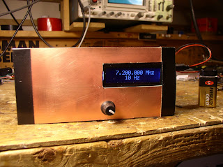
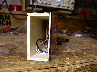
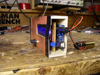
I am currently struggling with some DNS server problems. Dean KK4DAS is helping me. In spite of many years on the internet, this DNS problem has reminded me that, like Joe Walsh, I am an analog man. I mean, just take a look at my Mythbuster rig: (1382) Mythbuster for Lamakaan ARC – YouTube
But there are limits to my analog fanaticism. First, while Joe proclaims that he is looking for an analog girl, I very luckily found a digital girl. Elisa is quite digital. Second, even though digital tech is not my thing, I am willing to accept its usefulness. I mean, there is so much we wouldn’t be doing if we were all “analog men.” Like going to the moon.
This is a hobby — it is all for fun. Whatever floats your boat, right? Still, Joe’s song reminds me a bit of the old “SPARK FOREVER!” that you can still see on old QSL cards. That’s kind of sad. I just recognize that my comfort zone is more analog than digital.