
 |
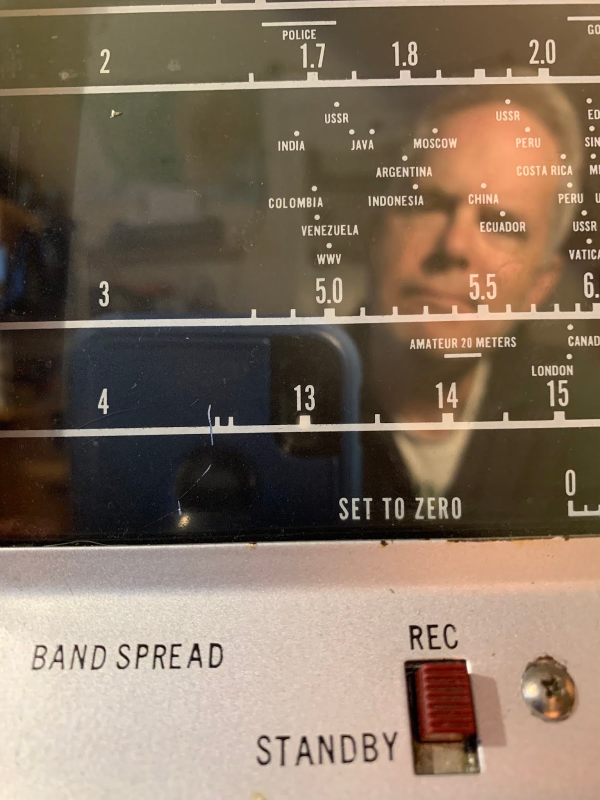
| Java on the S-38E Tuning Dial |
SolderSmoke Podcast #220 is available
Hunkered Down. StayInTheShack: SITS! Flatten the Curve! It is working.
Teaching English again – via Zoom. Kids completing the school year remotely.
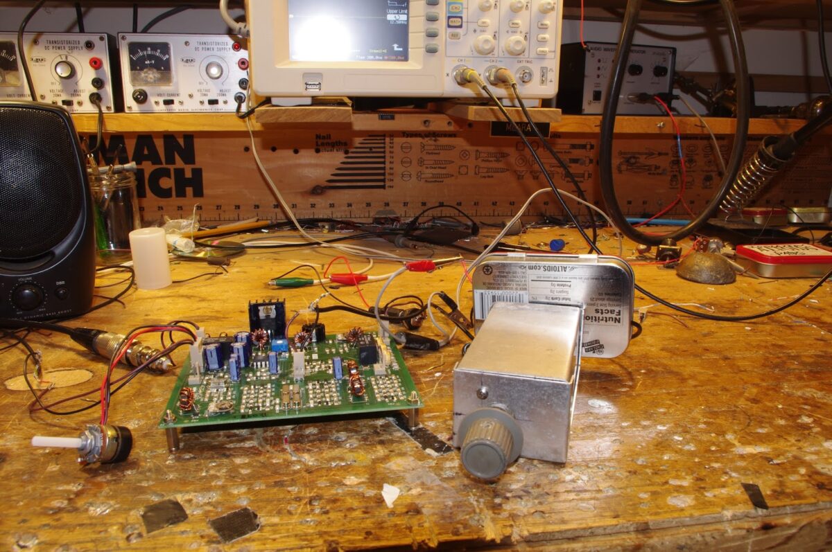
BILL’S BENCH
— Finishing up on the S-38Es.
— I wrote up my alignment, isolation and dial string experiences.
— S-38E work is causing me some serious legal problems. They are threatening to take down our sites and our podcast. Google has put a CEASE AND DESIST ORDER on my blog: Check it out https://www.homebrewradio.us/blog/wp-content/uploads/2020/04/CEASEANDDESIST.jpg
–S-38E caused me to want to get my HRO dial receiver on the SW broadcast bands with a good AM detector.
— Next up: Hayseed Hamfest cap for my Drake 2-B. And I have an idea on how to easily broaden it for AM: Tap the 455 kc output on the Q multiplier jack. 455 AM detector to audio amp.
SHAMELESS COMMERCE DIVISION
PETE’S BENCH
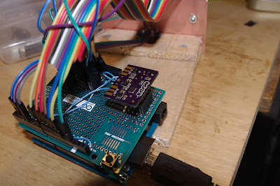
AD9833
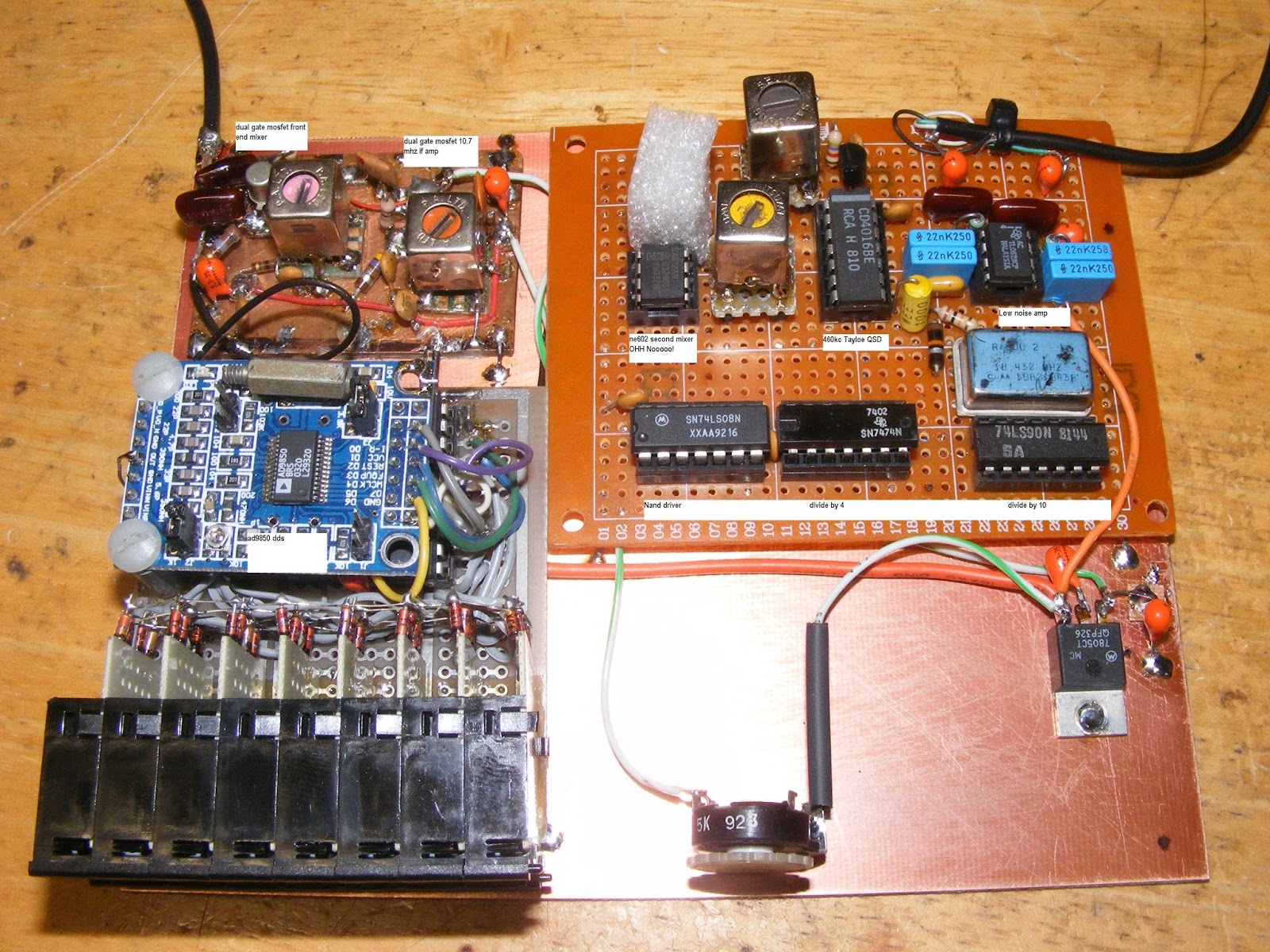
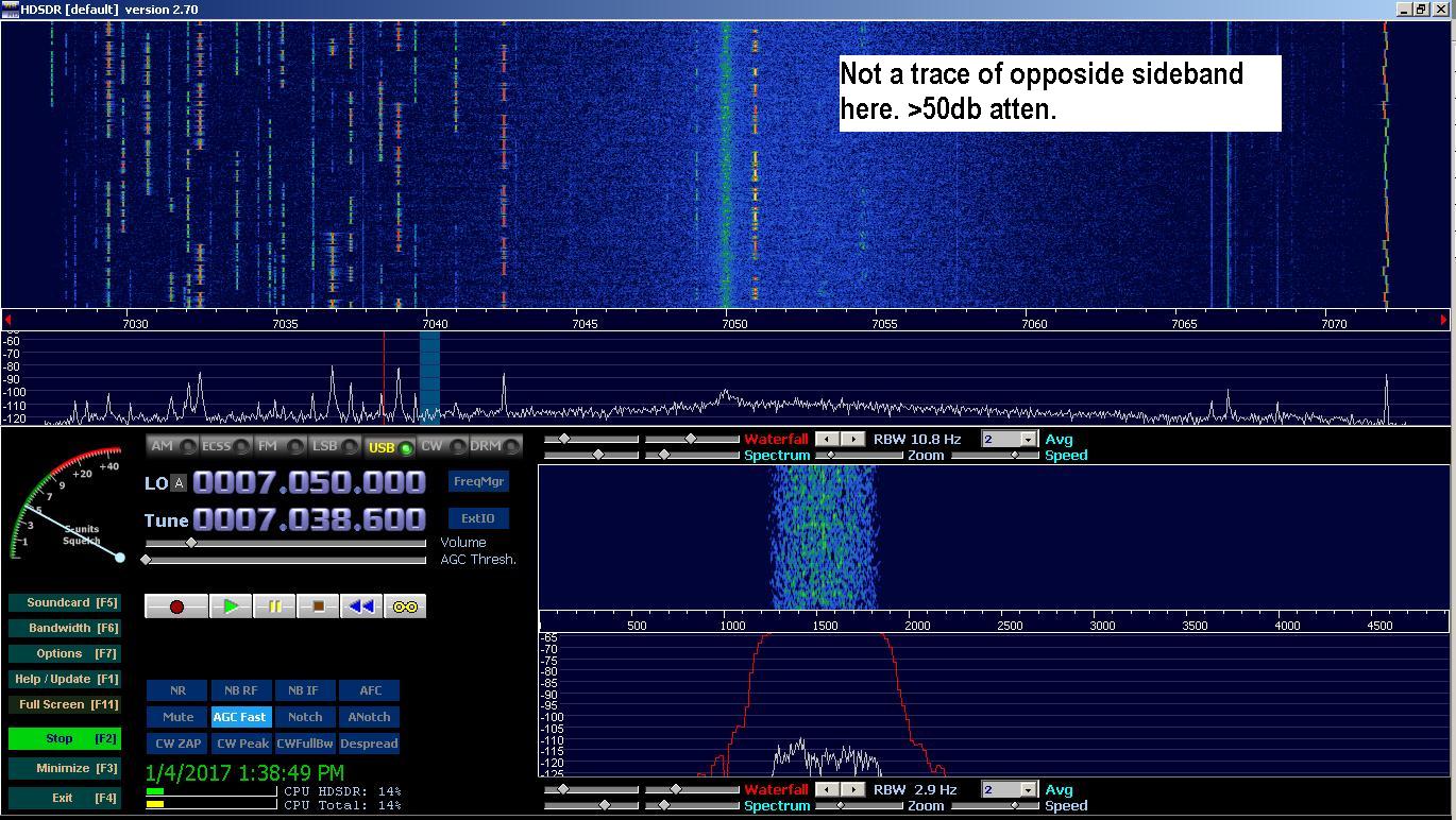
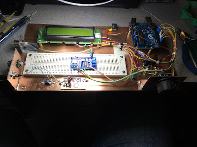
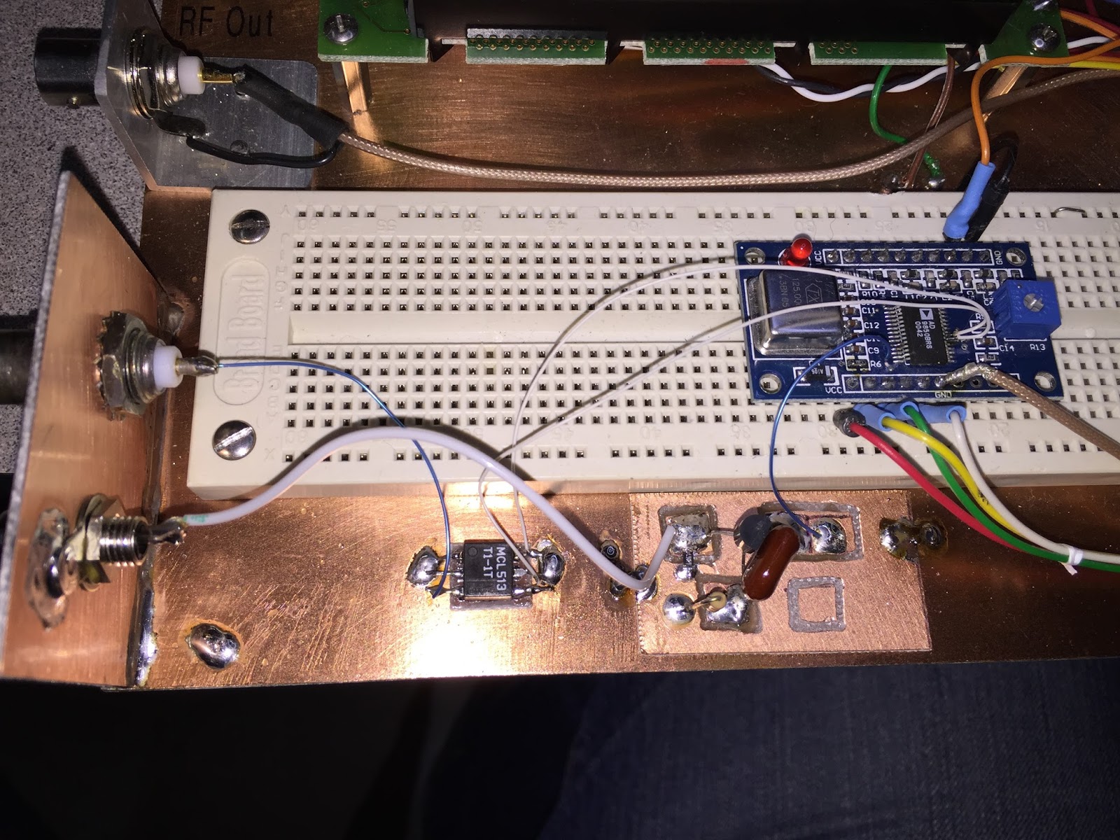
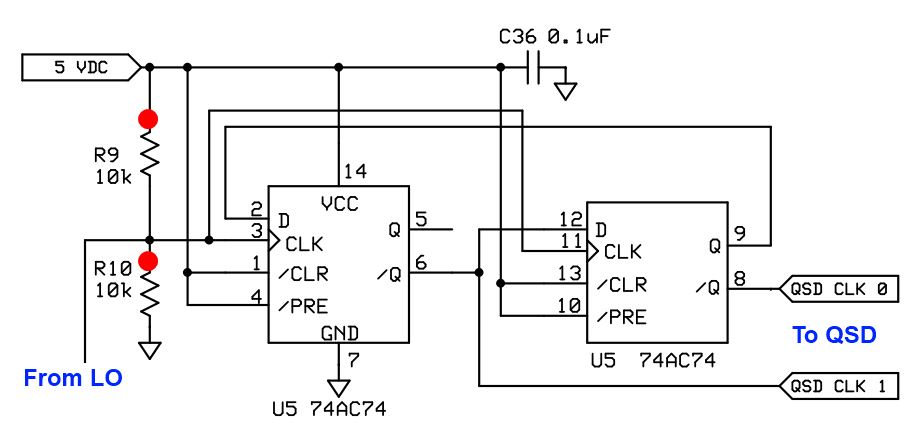
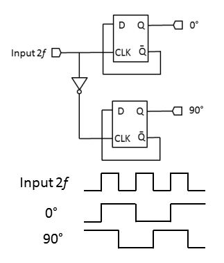
Phasing Rig Project
.
DEAN’S PROJECT – Step by step. Trouble shooting. Understanding. Receiver triumph. FB.
MAILBAG
Jack 5B/AI4SV doing well in Cyprus
Daniel SA7DER listens during commute in Sweeden.
Peter VK2EMU building a 6 meter amp. With Tubes
Jim WA8ZHN says there are still 7751 Novices on the books. FB.
Mike WB2BLJ modding his BITX – having a lot of fun.
Fred KC5RT – Great idea on isolation transformer in my S-38E.
Jerry Palsson: S-38C’s curves vs. S-38E’s exotic places. Java.
Anonymous mail: FT-8 DX — Are these contacts legitimate? See below.
Dear Bill and Pete:
I’ve been meaning to share with you something that has come to my attention by a rather circuitous route.
As you guys know, I’ve been involved in the software/IT side of ham radio for many years. I’ve watched many digital modes come and go. I’ve always enjoyed my work, but lately I’ve seen something that makes me uneasy.
I’m sure you guys have heard of the fantastic DX that is being worked by many guys using FT-8. It seems like all they need to work Jakarta is a couple of watts to a wet noodle. Shazam! Contact!
Well, I learned something that calls into some question the legitimacy of many of these contacts….
As i understand it, certain manufacturers, in cahoots with a major American ham radio organization (that happens to be very dependent on ad revenue from that manufacturer), have secretly set up a system that combines the internet and ham radio.
Here is how it works: Suppose Joe Ham gets on FT-8 on 40 meters. He puts out a call using his QRP transmitter and the aforementioned wet noodle. No way that signal is going to Jakarta, right? Well, it will with a bit of help.
The system has SDR transceivers and great antennas set up at strategic points around the world — these are really great locations — think mountain tops near the coastlines, always with high speed internet T5 connections. I think this is part of the whole “contest superstation for on-line lease” business model.
One of these stations picks up Joe Ham’s FT-8 call. Sometimes it will just re-transmit it, sometimes is will send it to a counterpart station on the other side of the globe. Bingo, Joe Ham’s signal is suddenly in Jakarta. A station there enthusiastically responds, and that signal goes back with the same kind of repeater/ internet assist. This is all done out of the reach of the FCC. They are usig overseas locations, some of them in Mexico.
Of course they have to be careful not to “facilitate” these kinds of contacts during times in which the bands are obviously dead, That’s why 40 is so useful for this system. Obviously they can’t keep this kind of thing secret forever — they just want to get guys hooked on FT-8, then they can reveal the system, selling it as nothing unusual, you know, sort of akin to Echolink.
Of course, this hasn’t been made public (for obvious reasons!) but I can tell you the name of the system: They tried to make it sound like something familiar (in this case like APRS): They call it “Automatic Private Radio Internet Link 1.” My understanding is that when they do their “roll out” they will offer the new service to those willing to pay a subscription.
Obviously as an old-school, traditional ham, I’m troubled by all this. What do you guys think? I wonder what your listeners would think.
Please don’t mention my name.. But here is a site that describes the new system:
Thanks and 73…
Please let us know if you have any information on this, or have observed any unusual and suspicious success with FT-8.


