Old Tricks, Lore, and Art — Freezing and Baking our LC VFOs — An Example from Cuba


Pavel CO7WT explained why Cuban hams used a process of thermal endurance to improved the frequency stability of their homebrew rigs:

——————–

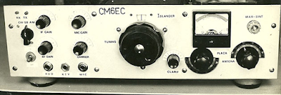
I’m CO7WT from Cuba, I started my endeavor in ham radio with a islander board.

They (FRC, like ARRL but in Cuba) made a print of a PCB to build the Islander, with component numbers and values, making construction fool proof, I think it was on the 90 or end of the 80…

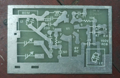
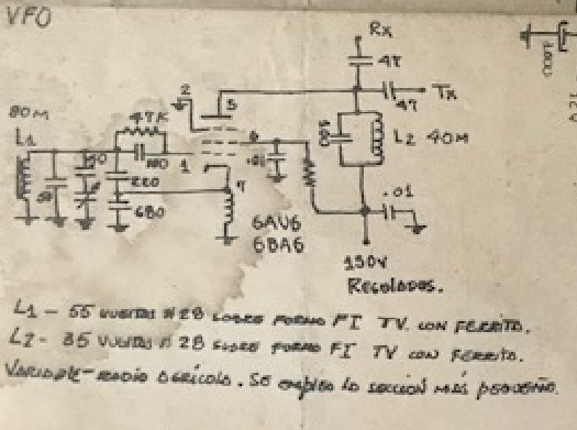
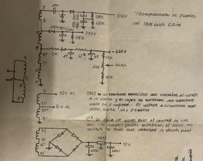
Mine was built with scraps from an old KRIM 218 Russian B&W TV as Coro’s explain, later on I get the 6bz6 and 6be6 tubes for the receiver (this worked better than the Russian parts) the VFO was transistorized, made with Russian components. A friend CO7CO Amaury, explain me a trick: thermal endurance:

For a week put a crust of ice on the VFO board by placing it in a frosty fridge during the night. Put them in the sun by day. This indeed improved stability, this was an old trick.

By thermal endurance I mean improving thermal resistance vs tolerance, meaning that tolerance doesn’t vary as much with temperature changes.

It’s crazy, but it worked!!

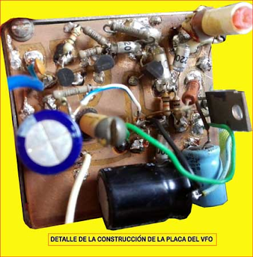
I remember that my vfo was on 7 MHz, with Russian kt315 as normal Russian transistors and capacitors, nothing 1-5%, 20% at most, it ran several khz in 5-10 min, mounted on a Russian “Formica” board (no PCB) and wired underneath.

After that treatment to the complete board with components and everything, including the variable capacitor; I managed to get it to “only” noticeably in the ear after 30-40 minutes.

To me it was magic!!

Basically, what I’m describing is just “thermal annealing”, but Cuban-style and with more extreme limits.

In a refrigerator you could easily reach -10 c and in the sun for a day in Cuba 60-80 celsius at least.

In Cuba in the 1990s-2010s many designs of DSB radios proliferated, both direct conversion and super heterodine (using an intermediate frequency)

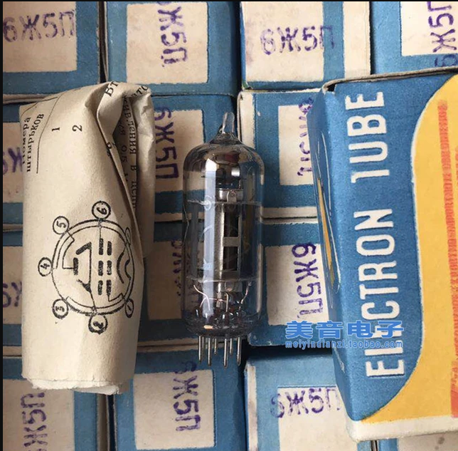
At first tubes and then transistors, mostly using salvaged parts, so it was common to find 465/500 kHz (if common Russian) 455 khz and 10.7 Mhz with or without “wide” filters since narrow filters for SSBs were not scarce: they were almost impossible to get.

Not only that, crystals, ifs, PCBs, transistors, etc.

Then, around the 2000s, Russian 500 khz USB filters began to appear (from Polosa, Karat, etc. equipment from companies that deregistered and switched to amateur radio) and that contributed to improving… Even though at 7 MHz 500kc if is very close.

I made many modifications with the years mostly from 1998 to 2004 ish… better filters in front of the first RX stage (same IF described between stages) improved selectivity and out of band rejection, remember we had on that days broadcast as low as 7100 khz

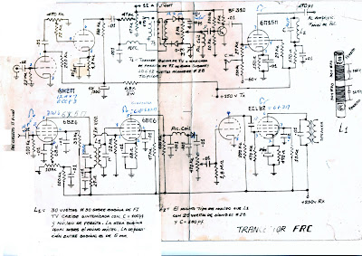
Tx part was a pair of russian 6P7 (eq. RCA 807) in paralell, etc.

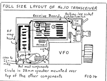
The Jagüey and others is one of those evolutions…

This is something I remember…

73 CO7WT

—————-

This is not as crazy as it sounds. We can find versions of the same technique in the writings of Roy Lewellan W7EL, Doug DeMaw W1FB, and Wes Hayward W7ZOI. I found this 2007 message from our friend Farhan VU2ESE:

I think the word ‘annealing’ is a bit of a misnomer. the idea is to thermally expand and contract the wiring a few times to relieve any mechanical stresses in the coil. after an extreme swing of tempuratures, the winding will be more settled.
this techniques owes itself to w7EL. I first read about it in his article on the ‘Optimized transceiver’ pulished in 1992 or so.
but all said and done, it is part of the lore. it needs a rigorous proof.
– farhan

https://groups.io/g/BITX20/topic/copper_wire_annealing/4101565?p=,,,20,0,0,0::recentpostdate/sticky,,,20,1,860,4101565,previd%3D1193595376000000000,nextid%3D1194269624000000000&previd=1193595376000000000&nextid=1194269624000000000


And here is another example of coil boiling:

https://www.qsl.net/kd7rem/vfo.htm

———–

I can almost hear it, all the way from across the continent: Pete N6QW should, please, stop chuckling. Obviously these stabilization techniques are not necessary with his beloved Si5351. Some will see all this as evidence of the barbarity and backwardness of LC VFOs. But I see it as another example of lore, of art in the science of radio. (Even the FCC regs talk about “Advancing the radio art.” ) This is sort of like the rules we follow for LC VFO stability: keep the frequency low, use NP0 or silver mica caps, use air core inductors, keep lead length short, and pay attention to mechanical stability. Sure, you don’t have to do any of this with an Si5351. Then again, you don’t have to do any of this to achieve stability in an Iphone. But there is NO SOUL in an Iphone, nor in an Si5351. Give me a Harley, a Colpitts, or a Pierce any day. But as I try to remember, this is a hobby. Some people like digital VFOs. “To each, his own.”


Thanks Pavel.


A Soviet Tube in Cuba: The “Little Spider”

I hope readers have picked up on the discussion of the Islander DSB rig out of Cuba. We had a bit of a breakthrough on this recently. I’ve been writing about it on the blog:

https://soldersmoke.blogspot.com/2024/04/re-building-islander-dsbcw-rig-in-cuba.html

One thing I think is especially interesting: The Cubans were using parts taken out of old Soviet TV sets. One of the tubes used in the VFO section of the Islander was known among the Cuban hams as “the little spider.”

Arnie Coro CO2KK explains why:

“VFO is made with ONE of the 6 “little spider” 5 pentodes… By the way, I am sure you will like to know why the tube is locally known like that… the ZHE letter of the Cyrillic alphabet is something difficult to pronounce to a Cuban – or any other non slavic for the matter – and it resembles like a little spider on the tube’s carton and… that’s why it is not a 6 “ZHE” 5 but a 6 “little spider” five!!!”

Re-building the Islander DSB/CW Tube Rig in Cuba

The VFO Board
The “motherboard” for an Islander
Islander boards recently obtained in Cuba by CO7WT

Pavel CO7WT is making great progress in re-building an Islander DSB rig, the same kind of rig that got him started in ham radio, and that was so popular in Cuba years ago. Here are some background blog posts on this rig: https://soldersmoke.blogspot.com/search?q=Islander In essence, the Islander was the earlier tube DSB/CW rig; the Jaguey was a later, solid-state DSB/CW rig.

When they get this Islander going, hams outside Cuba should definitely try to work this re-creation of an important rig.

Thanks Pavel for all the information. I will share with the group info that Pavel sent about temperature stabilization techniques used on this rig.

Pavel CO7WT writes:

Great news, today I received the package from my colleague in zone 6.

Two original islander motherboards and one from the vfo!

I’m doing a search among old technical friends in the city and in the country to see if I can put together at least a transceiver motherboard.

Audio triode-pentode is easy, as is tx pentode and audio double triode.

The difficult ones would be the 6cb6 and 6bz6 of the receiver… At least according to what I have polled among my local friends…

Tomorrow some friends are going to start looking for bases and valves that can be used to build a trx islander.

All out of pure nostalgia. I intend to make it qrp, that is, up to the output pentode, which there is between 3-5W of power, that is enough for me.

I am looking for alternatives for small sources, perhaps I will use switching for the filaments and we will see what I can get for the 180-250v of the plates.


Earlier:

CO7WT here, built a pair of the Islander back in the time, the most scary part was the power supply.

The 600V is 300ish V from the transformed DOUBLED stright from the transformer and if you look closely on the diagram the doubling capacitor need to be of good quality otherwise it will explode in the spot.

As you can imagine, using scrapped parts means that very often this capacitor explodes, even after a few months of duty, that was a common problem.

We used to use 47uF/800v from Germany that was almost easy to obtain, but exploded like fireworks a given day.

Later I learned that if you put a resistor of about 1k 5W in series and work it for a while like this [no real voltage at the end] it will behave in the future and this trick saved many, a trick that was shared with Coro CO2KK and he found the explanation on the taming/training of the dielectric after storage/inactivity will prevent it from exploding.

I think he made mention this on a DXers Unlimited program…

A Cuban Knack Story, and a Pandemic (SITS!) SSB version of the DSB Jaguey Rig — Viva el Cacharreo!

First, the Knack Story. Andy CO2AFV clearly has The Dilbert Disease:

Hello my name is Andy. I had an interest in Ham radio before knowing that existed. While I was a child my entertainment was building quartz oscillators that later I tried to receive on neighbors’ and friends’ radios. One day I succeeded in modulating two of them and I finally established a conversation with a friend about 200 meters from my home!!!

Andy with his FB HB rig
Here’s a description of a version of the 7 MHz Jaguey transceiver that Andy built during the pandemic. It looks to me as if he took the Jaguey DSB rig and added a 455 kHz filter with an additional mixer to turn it into an SSB rig. So he is generating the SSB at 455 kHz, and mixing it with a VFO running at around 6.8 MHz. The sum output would put you in the 40 meter band; the difference output at around 6.35 MHz could (mostly) be knocked down by a bandpass filter. I think the Cuban Radio Federation Web Site gets it a bit wrong — the purpose of the filter is probably to eliminate the unneeded sideband, not really to suppress parasitics.

Federation of Radio Amateurs of Cuba Published: September 17, 2020 Viewed: 2352 Comments: 12

Radio Transceiver CO9BIA 455 A construction carried out in times of Pandemic by its author, Andy Fernández Valdespino (CO2AFV).

Cuban radio amateurs continue to accept the challenge of isolation caused by the incidence of COVID-19, but this does not mean they paralyze their activities. Such is the case of Andy Fernández Valdespino (CO2AFV), who for more than four months has been working on the development and construction of a new transceiver, the CO9BIA 455, a device that already works perfectly in the 7 MHZ Band.

Andy, who is technical secretary of one of the Havana Radio Clubs, has to his credit the construction of two Jagüey-type radio models, as well as several types of interfaces for programming and Digital Modes; and various prototypes of antennas, among other elements that make up its constant “cacharreo” activities, as we say in our language.

He has now completed and tested a new model that he has named with the callsign of his Radio Club, CO9BIA, and the model 455 is due to the use in this prototype of a filter of the same capacity. Asked about the details and other construction bases of this radio, whose transmission and reception tests using only outputs from the driver were carried out on September 14, Fernández Valdespino pointed out that his objective was to build a portable QRP equipment, of very large proportions. small, that it would be capable of being operated in the 40 meter band on both sides, by incorporating an improved VFO from the traditional Jagüey, but this with some modifications, and that the radio in question would work powered by a 7-inch battery. .2 volt, the same ones that come with most of the “Handy” used by radio amateurs.

To complete the “portability” characteristics of the new radio, the possibility of exchanging antennas has been incorporated, and a very light variant of the telescopic type can also be used, just over one and a half meters long. Andy explained that for the development of the new equipment, he was based on studies that he has been doing on some of the characteristics of the Jagüey, a direct conversion radio with very good sensitivity, but that does not have good selectivity, so in the conditions of the current solar cycle, its behavior is not optimal. In Jagüey, the signals, after being modulated, do not pass through any band-pass filter, which causes many “spurious” signals to be released into the ether, which represents an obstacle to be solved in order to incorporate a linear that can increase its output power. All of this, the creator assures, was taken into account for the construction of this new design. For example, in the transmission step, in the CO9BIA 455, the microphone signal is mixed, pre-amplified, filtered and re-amplified, until it is delivered to the 455 kHz filter, to finally be mixed with the VFO signal; and as a result of these steps, the sum and subtraction of these mixtures is obtained, which are in the order of 6 and 7 MHz. As a final result, after these signals are injected into the input bandpass filter, only one output is obtained of 7 MHz, whose operating segments are carried out through the use of the improved VFO. Given these characteristics, with which spurious signal outputs are reduced or eliminated, in this new radio it is feasible to add a linear that can raise the power to approximately 7 watts, which would adjust to the power conditions described above.

This experienced “clunker” says that for the development and construction of this transceiver, three fundamental aspects were combined: the first, applying the experiences of having built other radio models, to ensure that the new prototype could be built by any radio amateur. with minimal knowledge of electronics, using recycled components and materials. Secondly, he used and adapted parts of the construction schemes of a radio project called LU3DY, from the Argentine Radio Club “Almirante Brown”; and finally, the adaptation of some parts of the traditional Jagüey, such as the VFO board and circuit. Although, as already explained, the radio works,

Andy Fernández is immersed in the construction of a small linear amplifier similar to the ARARIHNA project, by a Brazilian radio amateur, as well as making final adjustments to what is already a reality: the conclusion and final adjustments of the new CO9BIA 455 Transceiver, a portable QRP device for the 40 meter Band, developed in these times when we must all stay at home, to protect ourselves from COVID-19.

By Luis Enrique Estrada Hernández (CO2BK) FRC Information System Coordinator

Circuit details.

The VFO Board
Here is the web site of the Federation of Cuban Radio Amateurs that describes Andy’s work:


And I learned a very useful Spanish word through this: “Cacharreo” is a Spanish word that means to tinker with something in an attempt to fix, mend, or improve it.
Thanks Andy! And thanks to Trevor for alerting me to this great project.

The Super Islander Mark IV — A Cuban DSB Transceiver Made From CFL Lightbulb Parts


Trevor Woods also sent us this report from Arnie Coro. It is not clear to me what difference (if any) there is between the Super Islander Mark IV and the Jaguey Five (described yesterday). But the bit about using parts from old CFL bulbs is interesting. This was something championed by Michael Rainey AA1TJ several years ago. See: https://soldersmoke.blogspot.com/2009/01/soldersmoke-98.html

and:

https://www.qsotoday.com/transcripts/aa1tj

April 2010:

Today, I will be answering a question sent by listener Bruno from Croatia… Bruno picks up our English language programs via Internet, but he is now also listening on short wave too. He sent a nice e-mail message asking me about the latest version of the Super Islander amateur radio transceiver, because he wants to build one.

Well amigo Bruno, the Super Islander Mark IV is now on the air, and results are very encouraging considering that it is a 40 meters band transceiver built using recycled electronic components.

The Mark IV uses a totally different approach to the receiver design, and it adds two solid state audio filters.

Amazing as this may sound, some of the electronic components used to make the Super Islander Mark IV transceiver came from the circuit boards of broken or damaged Compact Fluorescent Light Bulbs… and that means that there is virtually an endless supply of those parts.

Here is now amigo Bruno, and amigos listening to the program at this moment, a brief description of the Super Islander’s Mark IV receiver module.

It starts with a simple resistive signal attenuator that feeds a dual tuned bandpass input filter.

The filter has a limited bandwidth , chosen so as to limit response to out of band signals… The filter is followed by a cascode transistor radio frequency amplifier stage, that feeds a broadband four diodes product detector.

Low level audio from the product detector goes to the audio filtering and amplifying module, made with discrete transistors, of which several of them are also recycled from the Compact Fluorescent Light Bulbs circuit boards…

This version of the Super Islander, the Mark IV , is radically different from any previous ones, as we have now switched over to a totally low cost solid state design , that can be easily reproduced because it uses very common electronic components and straightforward , easy to adjust circuits.

In our upcoming mid week edition I will describe the VFO, or variable frequency oscillator and the transmitter module of this unique low cost amateur radio transceiver, the Super Islander Mark IV… about the lowest possible cost transceiver that will make possible regular two way ham radio contacts on the 40 meters band using either voice or radiotelegraphy modes.

The Jaguey Five — The Solid State Cuban DSB Rig — Circuit Description

Obviously we need a picture of a Jaguey transceiver.
“Made in Jaguey Grande”

Trevor Woods found this report from Arnie Coro (SK) CO2KK:

February 2009:

Here is now item three in detail: It was quite a long time ago, when I heard about a nice project sponsored by IARU, the International Amateur Radio Union, that was promoting the design of a kit, a simple single band transceiver kit that could be sent in a small air mail parcel to radio clubs in Third World nations which could then deliver them to would-be radio amateurs, and help them build and align the radios… But, unfortunately I lost track of the project, and as many of our listeners may realize there is still a great need of such a project… Past efforts along this line have had some problems, among them the mistaken approach of using of very sophisticated electronic components that in case of a breakdown would be impossible to replace locally; and also, all attempts seemed to try to make the transceiver an ultra- or near-ultra-miniature radio, something that won’t help at all with beginners…

So, when I recenlty received an e-mail from Canada, asking what I thought about reviving this great idea, our Canadian amigo asked what we had already done here in Cuba, with our JAGUEY double side band plus CW 10 watt transceiver that went up to REVISION NUMBER 5. , This was the last upgrade, done about three or four years ago, and we named it the Jaguey FIVE, as it generates 5 watts of CW… The Jaguey FIVE was a low parts count, not miniature, easy to build single band transceiver that used readily available components, instead of sophisticated state of the art parts…

In order to please the friend who wrote about this topic, here is a brief, on the air, description of our Jaguey FIVE and by the way, Jaguey is the name of a town, actually it is Jaguey Grande, or big Jaguey, and the Jaguey is a beautiful tropical tree… The original Jaguey transceiver originated in that Matanzas province town in 1982,

The receiver part starts with a simple yet effective RF attenuator, then it feeds a bandpass
filter made of two tuned circuits… we use shielded IF transformers from old TV sets 4.5 megaHertz audio chains… A simple bipolar NPN small signal transistor grounded base amplifier feeds a homebrew double balanced mixer… and we “discovered” quote, unquote, that the antenna balun transformers used in TV sets, the 300 to 75 ohms baluns, had a ferrite core with two holes that makes a wonderful broadband transformer for the double balanced mixer…

We use computer diodes removed from defunct ISA old computer cards and motherboards and developed a very simple test jig to match the diodes… The double balanced mixer is fed on the other port from a simple three transistor oscillator, of which we have two versions, one using three NPN bipolar transistors and the other one using an FET oscillator followed by two bipolars… at the output of the mixer we have AUDIO, as this is a direct conversion receiver, amigos!!!

Now we amplify the audio using discrete components and again we have two versions of audio filters, one with bipolar NPN transistors and the other using a very common operational amplifier IC… The audio power output stage also is available to the builder in two versions, one using discrete components and the other using an integrated circuit audio amplifier that is locally available here in Cuba and produces a booming 2 watts of audio, with a lot of gain and rather low noise! This is the audio IC used by the most popular TV set in use here in Cuba, so we were able to obtain them from the TV repair shops at low cost.

Well, that’s why I will describe as a flexible design… again, no attempt is made to make the Jaguey single band amateur transceiver a miniature rig, as miniaturization is definitely not for beginners!!! And following up this description of the receive section of the Jaguey, in our upcoming mid-week edition of Dxers Unlimited, I will describe the transmitter section of the rig,that shares the same variable frequency oscillator with the receiver…. I think that a new more up to date version of the Jaguey transceiver could very well be made available in kit form, with large-sized and easy to assemble circuit boards. The old Version 5 uses three circuit boards, one for the receiver, one for the VFO and one for the transmitter, so the newcomer can assemble just the receiver and start listening to amateur radio communications before having his or her own ham license!!!

You are listening to the weekend edition of Dxers Unlimited coming to you from Havana on the air and on the web at our Dxers Unlimited blog.

———————-

A video of Jaguey Grande, Cuba: https://www.youtube.com/watch?v=krblz_5o6jU

Earlier posts about the Jaguey on the SolderSmoke blog: https://soldersmoke.blogspot.com/search?q=Jaguey

Arnie Coro: Jaguey Rig Designed in 1982, More info on the Rig

Jaguey, Matanzas, Cuba


Dxers Unlimited’s mid week edition for 23-24 October 2007

By Arnie Coro Radio Amateur CO2KK
... 
My own personal experience with the original JAGUEY direct conversion 
transceiver, designed way back in 1982, is that when used with a well designed front end input circuit, those receivers provide amazing sensitivity, with signals as low as 1 microvolt easily detected but, they do have one drawback, their selectivity or ability to separated between stations is very poor. The direct conversion radio receivers are used for picking up CW Morse Code Signals , Digital Modes and Single Side Band, but they are not good for receiving AM signals, and can't 
pick up FM modulated signals at all...

The original JAGUEY 82 Cuban designed single band amateur transceiver, was tested against a sophisticated and really expensive factory built 
transceiver. The tests showed that our design was at least as sensitive as the very expensive professional equipment, registering a measured sensitivity of less than one microvolt per meter, producing perfect CW Morse Code copy of such a signal. Adding well engineered audio filtering to a direct conversion receiver can turn it into a really wonderful radio by all standards amigos. 

Radio is a fun hobby, and believe me amigos, there is nothing more magical than listening to a radio receiver you have just finished building !!!

-----

Peter Parker VK3YE Found a nice description of the Jaguey by Cuban radio Amateur Jose Angel Amador from the BITX40 Facebook Group: 

A translation. This was apparently in response to someone who thought they'd found a Jaguey schematic: 

"That's not an original Jaguey, that was a simple, single band, unswitched, 5 watt, DSB, kit for beginners with no gear and needing something to put on the license.
Carbon microphone direct to balanced modulator, two stages with 20 dB gain, W1FB/W1CER style feedback, and final with 2 x 2N2102 class B.
The receiver was more like that of the schematic, with a TAA263, easy to get from the FRC in 1978, and headphones. No need for an RF stage: the mixer was overloaded at night with European broadcasts above 7150.
The VFO is also inspired by Solid State Design for the Amateur Radio, a Colpitts with 2SC372 and a low gain feedback buffer with two 2SC372s.
Binocular ferrites were taken from Soviet TV baluns. The conditions of Cuba 1978.
Today I would make an SSB rig with polyphase networks, mixer with 4066, and VFO Si5351.
The big complication of BitX is the crystal filter, they either get it made, or stick to a recipe, but few have what is needed to measure and tinker with crystal filters.


Arnie Coro CO2KK (SK) Provides More Info on the Islander DSB rig

Peter Parker VK3YE found this message from Arnie CO2KK in the Wayback Machine. We continue to look for more information on the Jaguey solid state DSB rig.

Arnie wrote:

Several years ago an amateur in central Cuba was approached by some of his young friends to help them build their first rig. CO7PR, Pedro, a telecommunications technician for the phone company, had a vast experience both with vacuum tubes and solid state circuits, plus that special gift of designing and building with whatever is available. After a few days, Pedro came out with the “Islander” prototype, a low parts count, easy to build single band transceiver!

Here is the circuit description of that little radio that has provided many cuban young and old, newcomers to our hobby, with their first rig… and the challenge to improve it.


RECEIVER:

It is a direct conversion, YES, a DC receiver made with vacuum tubes. The very thought of having those tube filaments fed from the AC power supply and at the same time having 80 or 90 dB of amplification made me shudder when I first talked to Pedro on the very popular here 40 meter band! You are LOCO Pedro, I told my good friend… CRAZY, those poor kids are going to hear 50 percent 120 hZ hum when they tune across the 7 megahertz band.

Yes Arnie, you are right, it has a little background hum, but by using a small loudspeaker and small coupling capacitors… it’s tolerable! The receiver shares, in its original version, the same antenna input as the transmitter output stage, a PI network, but we soon learned to add a separate LC tuned circuit first and latter a bandpass double tuned input filter…PLUS a signal attenuator… a very primitive but effective attenuator… just a 10 k potentiometer!

For an RF amplifier stage the Islander uses a russian pentode, which is the equivalent of the popular TV IF amplifiers of the 50’s… looks like a 6CB6, for those of you that fixed TV sets 40 years ago or so.

The 6 “little spider” five, as everyone knows that tube here,has a lot of gain, and it can be kept rather stable by a judicious choice of screen and cathode resistor values.. Noisy pentagrid converter follows!

The 6A2P… a russian 6BE6, was the first tube type used in the Islanders, later some people tried the ECH81 triode-hexode and found it works better.

The circuit of the 6A2P-6BE6 is quite straighforward… a… you guessed right… PRODUCT DETECTOR… fed from the vacuum tube VFO… and providing its audio output to the two stage audio amplifier.

Audio amplifier is made with a triode-pentode tube of which plenty are locally available from defunct TV’s… the ECL82 and the 6F4P and 6F5P of east european and russian manufacture respectively provide a lot of gain.

So… that’s your receiver.. quite straightforward, works on 160, 80 and 40 meters by just changing the input filter and the VFO injection, it does NOT provide very good selectivity at all, but during the daytime, when the 40 meter band is used for local and regional contacts, it puts those new hams ON THE AIR!


VFO… the big problem amigos!

CO7PR worked very hard to try to make a stable vacuum tube VFO… and he almost made it..

YES, ISLANDERS drift, some not too much, others are not so good, depending on who built the rig, and how close they followed Pedro’s advice at first, and Arnie’s CO2KK later (as yours truly became quite involved in the project, as soon as I found that it was THE way of getting all those guys ON THE AIR!)

VFO is made with ONE of the 6 “little spider” 5 pentodes… By the way, I am sure you will like to know why the tube is locally known like that… the ZHE letter of the Cyrillic alphabet is something difficult to pronounce to a cuban – or any other non slavic for the matter – and it resembles like a little spider on the tube’s carton and… that’s why it is not a 6 “ZHE” 5 but a 6 “little spider” five!!!

The VFO cleverly works at one half the operating frequency… and then it DOUBLES frequency at the plate circuit… output is via a link to the pentagrid or hexode mixer depending on which type you use.

BUT… the VFO also has a second output to the transmitting chain.. Well that’s the receiver… OH YES… the VFO is fed from a VR tube, a gaseous discharge voltage regulator similar to a VR-150 or VR-105… CO7PR advises to use the VR105, but when building the Islander, special in the countryside, that’s a very hard part to find, as old TV sets don’t use VR tubes! So people use whichever VR they can find. ZENERS? They are only available locally for 6 to 24 volts, so they can’t be used with this rig.


ISLANDER DSB AND CW transmitter circuit:

From the VFO plate circuit, you pick up 7 mHz energy (usually you must wait at least half an hour for that said 7 mHz energy to be stable enough in frequency) and feed two diodes (ex-video detectors from russian TV type D20) acting as what I like to call BALANCED AND UNBALANCED modulator!

When used for DSB, it is certainly a DSB generator… but when you want to work CW, it must be UNBALANCED.something easy to achieve with just a resistor from the +12 volts line and a switch!

The balanced modulator receives its audio from a carbon microphone capsule salvaged from an old telephone, and conveniently connected to same +12 volts with some additional filtering via biggest possible electrolytic + small ceramic dogbone from TV set IF amplifier as RF bypass… no dogbone capacitor there… strange howls on Islander audio as RF leaks into balanced modulator you know.

So dogbone ceramic capacitor is a must! No, disk ceramics are not locally available, so people must use the next best choice… dogbone ceramics in the 100 pf to 5000 pf range, usually rated at 300 volts or so… (that 300 volt rating we learned the hard way, but more about that later.)

The original version of CO7PR’s Islander ran with the carbon microphone, no MIC LEVEL control option, as he really wanted to keep things simple… later versions have audio preamps of various designs, and some even have a sort of primitive compressor.. From the balanced modulator the DSB (plus a little carrier leak that is always there) drives the rig’s one or two transistor low level RF amplifier, which is made using whatever NPN silicon transistor is available, usually KT315’s salvaged from TV’s too. the KT315 is sort of a russian version of the 2N2222, so you understand why we use it here!

RF voltage reaches then the grid of an ex-video output amplifier vacuum tube, and there you are… about 2 to 5 watts of either DSB or CW on 40 meters and a new cuban amateur ON THE AIR!

Before I forget… keying… a little chirpy always because of so many interactions between simple circuits, sometimes not too well shielded, first time builder etc.

BUT… ISLANDER is ON THE AIR providing that young kid from the local junior high school or that doctor that always wanted to be a ham, or maybe the fresh out of school electronic technician, with the fascination of their first ever rig. YES, they drift, and some drift badly, when the frequency determining capacitors in the VFO are not too good… (most of the time), as I said they are a little chirpy. and the receiver’s selectivity makes working 40 meters at night almost impossible (although some wizards do make nightime contacts at the low end of 7 mHz) BUT. YES, they are ON THE AIR.

Today there are a few Islanders still on the air, and some are even still built brand new (with many of CO7PR’s and CO2KK’s mods), but the trend is for all solid state rigs centered around CO5GV’s and CO2JA’s prototype the “JAGUEY,” a design that draws a lot from Wes Hayward’s Solid State Design for the Radio Amateur, and as of late, with lots of ideas coming from SPRAT, the G-QRP club magazine and QRPp from NORCAL, the Norther California QRP club!!!

In a future posting I will describe the “Jaguey,” too.

————-

More info on the Cuban DSB and AM rigs can be found here:

https://soldersmoke.blogspot.com/2023/04/more-info-on-cuban-jaguey-solid-state.html

https://soldersmoke.blogspot.com/2023/03/homebrew-am-from-cuba.html

https://soldersmoke.blogspot.com/2023/03/more-cuban-homebrew-from-80s-and-90s.html

https://soldersmoke.blogspot.com/2023/03/schematics-for-cuban-islander-double.html

https://soldersmoke.blogspot.com/2023/03/the-islander-homebrew-dsb-rig-from-cuba.html

https://soldersmoke.blogspot.com/2023/03/needed-more-info-on-cuban-islander-or.html

More Info on the Cuban Jaguey Solid State DSB Transceiver

ZL2BMI Transceiver Layout (not full size here!)

Continuing our search for information the Cuban “Jaguey” DSB rig, Trevor Woods pointed me to Dick Pascoe’s QRP column in the (below) July 1998 issue of Ham Radio Today. I think the first SPRAT article about Eric Sears’ ZL2BMI DSB rig was in SPRAT 83 in the summer of 1995. This fits well with the sequence described below by Arnie Coro CO2KK.

I am still looking for a schematic and pictures of the Jaguey rig: If you can help in this, please let me know.

Homebrew AM from Cuba

Jose CO6EC sent us more information about homebrew rigs built in Cuba. The transmitter above is a thing of beauty. I am really glad that Jose has held on to it. Thanks Jose!

Jose CO6EC today

Jose CO6EC writes:

This is another work from that time: an AM and CW transmitter of about 100W of power, with an on-board modulator. It was taken with some modifications from a Handbook from the 50s. Here goes: it was built with what we had on hand at that time, it still exists, I keep it as a relic of those years.

It used combined Soviet and American tubes in the RF sections: Soviet 6P9 and (2) 6146. The modulator used Soviet 12AX7, 12AUT and (2) 6P7. The 6P9 works as a crystal oscillator, and in case of using an external VFO it works as an amplifier and doubler or tripler to obtain outputs in the 160,80,40,20,15 and 10 Meter bands.

The VFO was also taken from a 1949 Handbook if I remember correctly, but I don’t have any literature on that, as you can see in the photo it has 5 5u4c rectifier valves, VR150 voltage stabilizer, 6v6 output, another 6v6 as a separator and a 6 )I(4 (60I94?) Soviet, in the oscillator. The stability they achieved in those years is incredible, I could communicate with stations that were on LSB and if I didn’t tell them that I was on AM they didn’t notice.

As a receiver I used an old Soviet AM and CW receiver, used by the Aviation HF stations of the 40s, which no longer exists hihihihihi

I’ll tell you how I tuned all that good ftuff: First I put the receiver in CW to beat the signal of the stations in SSB. After hearing them clearly, I removed the oscillator of the receiver and connected only the VFO of the Transmitter, and beat the signal with that of the receiver until I heard the other station clearly, then I put the transmitter to work and was ready to communicate.

There were many communications made with that station, even internationally on phone and CW.

Today everything is easier because with transceivers it is not necessary to go through all that work, but it is always good that those who did all this work know how radio was built and made.

73 Jose CO6EC

Obviously the transmitter

The two pictures above must be the VFO. It looks like the VFO in the 1947 ARRL Handbook.

I wonder what handbook this was? Spanish language.


More Cuban Homebrew from the 80’s and 90’s — A 160 Meter AM (Controlled Carrier) TX with Soviet 6P23s

160 Meter Transmitter

Jose CO6EC writes:

I will be sending you some work of homebrew from the 80’s and 90’s when practically everything was manufactured by Cuban radio amateurs

The photos are of a Modulated Amplitude TX for the 160 Meter Band, about 25W of which several were made. The final tube was modulated in many cases by a 6DQ6, 2E26 or other similar ones that were very abundant at that time.

This one in particular is made with valves 6BH6 for the VFO, 6CL6 for the amplifier step and 6P23 Soviets in the final part, the modulator was made up of a 12Ax7 microphone preamplifier and a 6BM8 that came out through the cathode to the screen grid of the 6P23, in this way the carrier was controlled by modulation what we called Carrier Control as there was no voltage on the grid at the ends there was practically no carrier in the air which gave the impression of transmitting in SSB. hihihihihihi

For those who did not have a communications receiver, a conventional radio was adapted to receive that band, which in many cases was a VEF-206 of Soviet construction, to which an oscillator was adapted to beat the signal and get exactly on frequency. This was very popular here in the late 80’s and early 90’s.

Thanks Jose. We look forward to learning more about Cuban homebrew. The way in which radio amateurs got on the air with gear that they made themselves using the limited parts available to them is really interesting and admirable. 73 Bill

Schematics for the Cuban Islander Double Sideband Transceiver (Please Send More Info)

Jose CO6EC has been digging up 30 year-old Islander schematics for us. Thanks Jose. This one shows a VFO for the Islander. Note that it runs on 80 meters, but they select the second harmonic at 40 meters. This was a smart move that surely helped with VFO frequency stability.

Jose sent this printed circuit board pattern for the VFO. Obviously they were making many of these rigs.
Here is the power supply. Jose reports that the transformer came out of a Soviet Krim 218 TV set. As a kid, I also pulled a transformer out of an old TV — I did it to build a power supply for a Heath HW-32A.
Here is another version of the Islander. Click on the image for a better view. Jose reports that this version was circulating during the time Islanders were being built. He says this diagram many have been done by Arnie Coro CO2KK (SK), and may have been circulated on the internet.
Here’s the first schematic that Jose sent. Again, click on the image for a better view.


I will continue to gather information on the Islander and the Jaguey. If you have any info please send it to me.

Here are some earlier posts on these rigs:


Thanks to Jose CO6EC!

The Islander — A Homebrew DSB Rig from Cuba

This article, the pictures, and the comments are all so cool. They really capture the spirit of homebrew. Obviously we still need more information on the Islander and the Jaguey. If you have it, please send it to me and I will disseminate it via this blog.


I’ve been in touch by e-mail with Jose Campos CO6EC (the guy in the picture above). He sent me this partial schematic of the Islander (we still need the VFO circuit and the RF amplifier) . Thanks Jose!

Views: 2274
Comments: 6

Remembering

By José de Jesús Enríquez Campos (CO6EC)

Next 2019 will be the 30th anniversary of the first convention of radio amateurs in the province of Villa Clara, in Campismo de Ganuza, municipality of Corralillo, on the North coast, about 100 kilometers from Santa Clara, the provincial capital.

This convention was held on a national basis and colleagues from all the country’s provinces participated at that time. We did not reach a thousand members throughout the national territory and most of the radio amateurs worked in the 40-meter Band in Amplitude Modulation Then the Lateral Side Band (SSB) was the privilege of a few and the 2 meters was something rare, which did not yet exist in our environment.

At that meeting, a project for a Tube Transceiver was presented, quite simple, with just six vacuum tubes and a BF310 transistor. It was possible to work in HF in Double Sideband, achieving a greater efficiency than the transmission in Modulated Amplitude (AM). This project became known as the Islander.

In only two printed plates, one for the VFO and another for the TX and RX part, which by the way were printed for distribution, in a company in Villa Clara, due to their easy construction and acquisition of the components (almost all of them came out of a Krin-218 TV), a large number of such equipment were manufactured by radio amateurs from all over the country. Like everything made at home, it always comes up with a little problem that later is necessary with tinkering, correcting it.

I remember listening to an old radio amateur from Havana (whose callsign I don’t remember) in a pleasant QSO with another colleague, who jokingly said, “… some “Bugs” have now appeared in the band, called Islander, which is worse than the invasion of the Vikings…”, which gives an idea of ​​how many were built at that time, when if you wanted to make radio, you had to manufacture it, something unusual in these times.

As soon as we saw the project we decided to build it, because at that time we had an AM “transmitter” with modulation by “Carrier control” with four tubes, a 12AX7 preamplifier; an ECL82, as a modulator, with cathode output to the final tube Screen grid, a 6DQ6 and a 6BH6 as VFO; and to receive, an old Russian receiver from World War II.

We got involved in the construction and improvements of the project and we managed, with some changes, to improve its performance and quality, because among the modifications to the original, we added:

-A switch, with which you could change the transmission mode to DSB -CW-AM.
-A “Pi” Filter at the input of the RX, which considerably improved its quality.
-An automatic volume control, because since it did not have AGC (Automatic Gain Control), when someone nearby came on, it would break your speaker.
-A filter for the microphone input, which improved the quality of the modulation.
-A final power stage, with a 6146B, with 750 V on the board, for about 70 W of output, taking advantage of the 6P15P as Driver.
-The chassis was built from scratch using aluminum trays that were sold at the hardware store for “four pesos” each and that were special for making cabinets for these purposes.

After the construction was completed in one afternoon, with Reinaldo Martínez Domínguez (CO6UK), from Manicaragua, the balanced modulator was adjusted, since the good transmission of this type of equipment depends on the relationship between the amount of RF and audio that are mixed At that stage, it took us a long time to adjust, until Reinaldo with his expert ear told me, “leave it there, don’t touch it, it’s 99% complete”.

There were many international contacts that I was able to make with this very simple equipment, with very good reports, many of them with Europe, the American continent, that was very normal, since the propagation conditions in those years had nothing to do with the today, you could do half the world in AM, with about 100 W.

Many colleagues at that time asked me what equipment I was using. When I told them it was an Islander, they asked me to send them the plans of the improvements made, they were many modified plans, mimeographed.

Perhaps the youngest do not know what that was and the photos taken by colleague Joel (CO6JC) that helped to illustrate the distribution of the components in the chassis, were sent to radio amateurs from the different provinces, in the interest of contributing modestly to migrate from AM to the Double Side Band, today it is a rarity to listen to someone on AM, there are already few who appear in Double Side Band, which shows that we have developed in these almost 30 years, despite the difficulties, which We went from just under a thousand to about 8,000 throughout the country today.

From time to time, a colleague in the 40 meter Band, from another province, has told me that he still keeps the plans and photos that were sent to him at that time, or as “Kike” (CO6GO) that he still has a Islander as a relic.

Ours passed away a long time ago and part of its components went to other projects, thanks to Joel (CO6JC) there is a graphic record of it, and that at that time I had hair, which I have lost in these bustles.

With this brief comment, we only want the new generations to know what radio amateurs were like in those days and the older ones to remember it.

Nothing, to remember is to live again.

Here he left you some images.


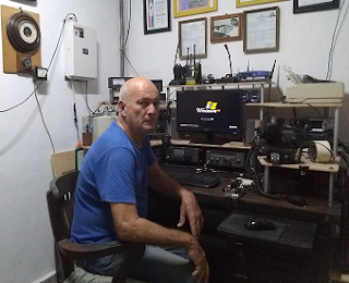
  • (co6ec) Jose de Jesus Enriquez Campos

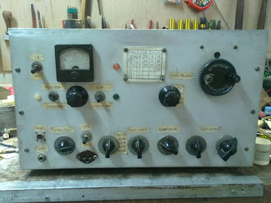
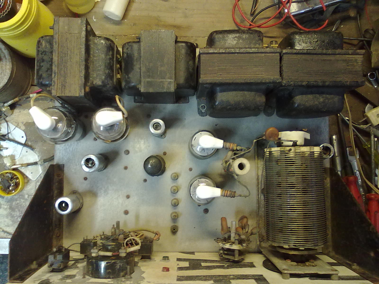
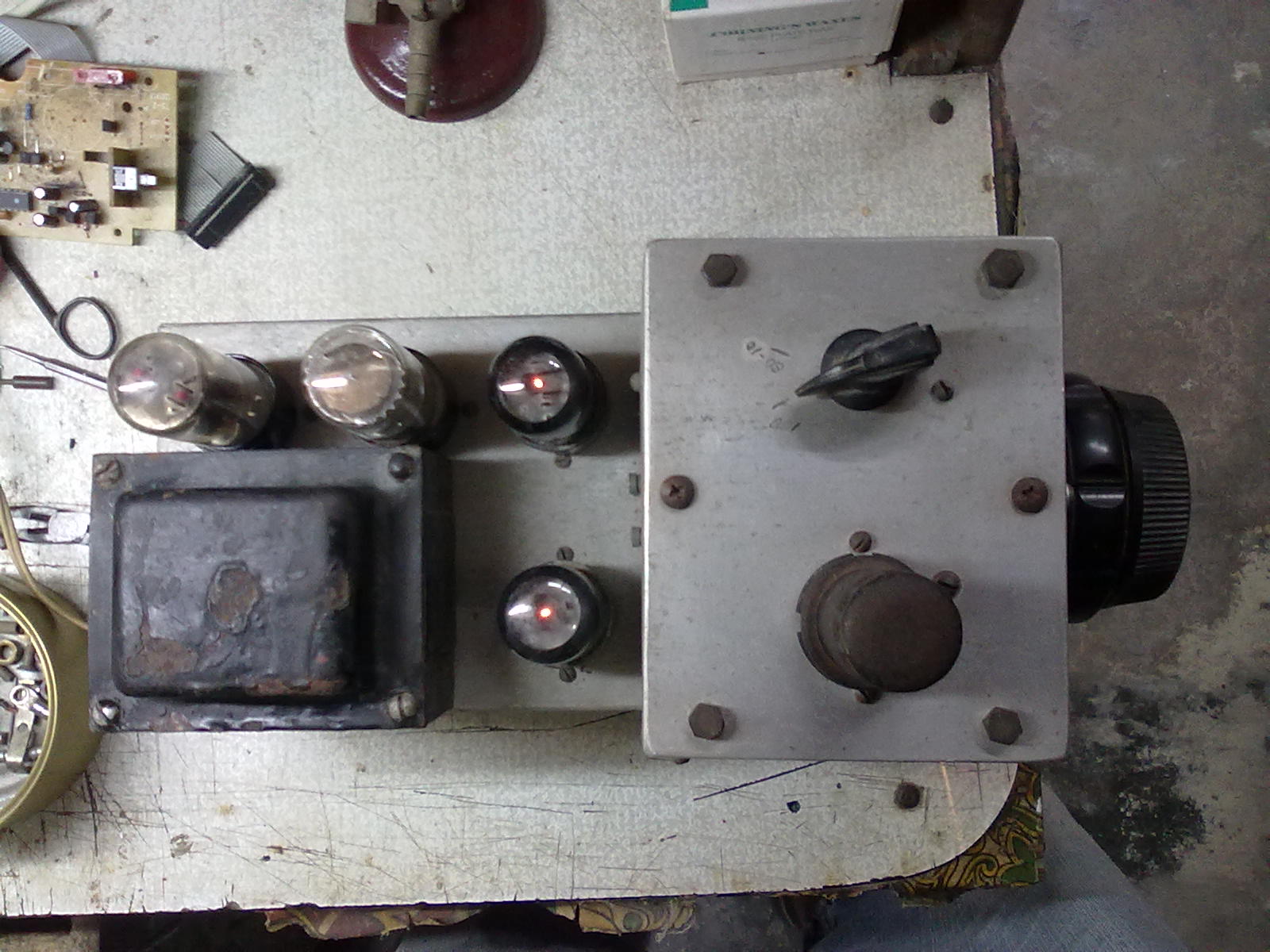
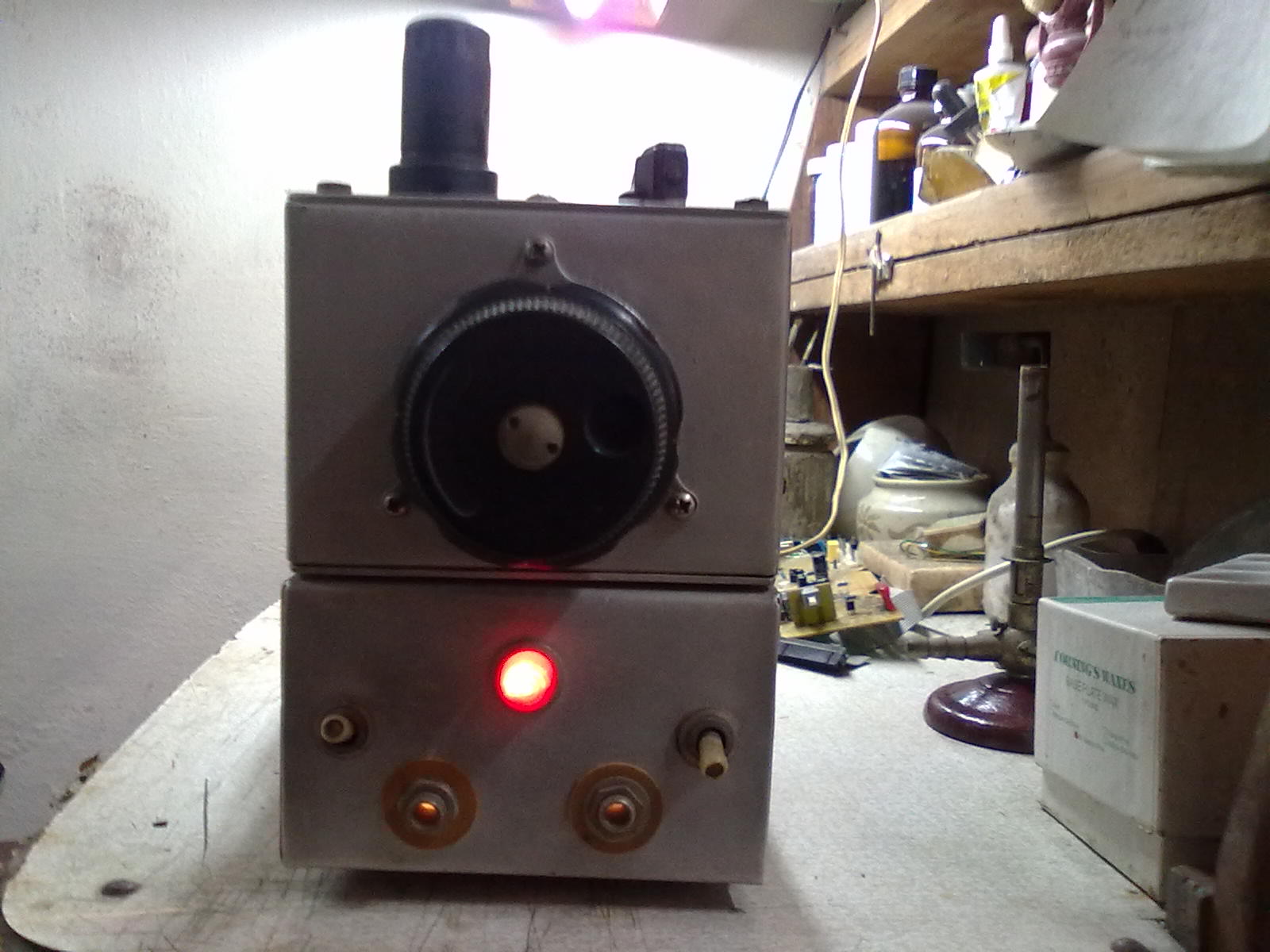
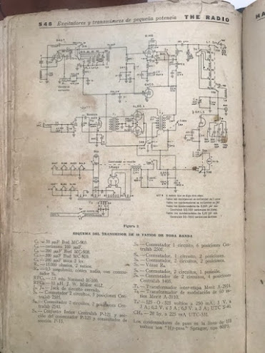
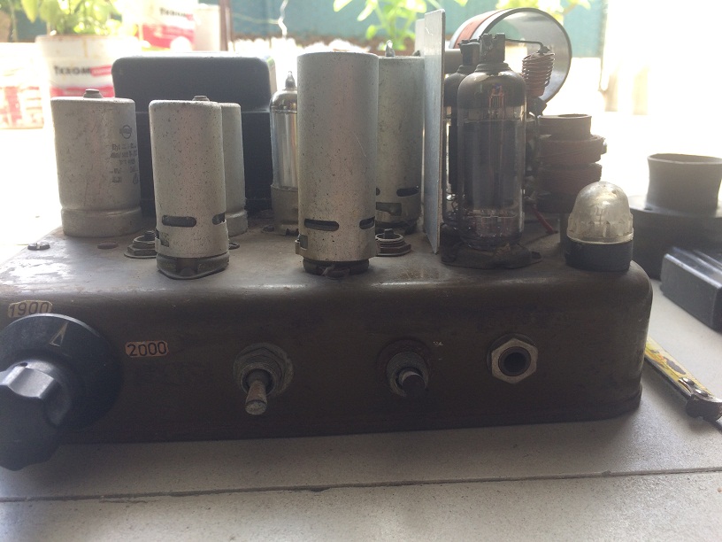
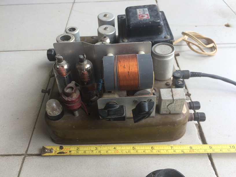
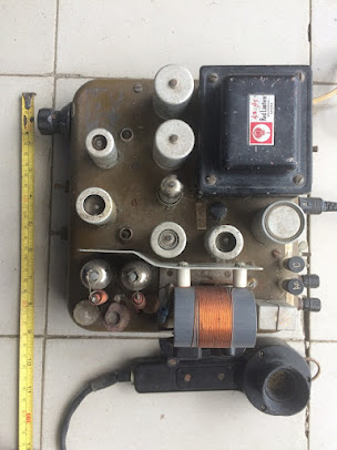
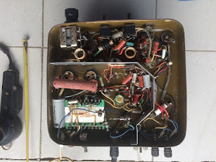
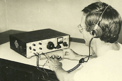
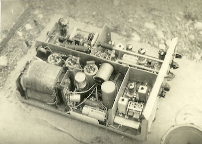
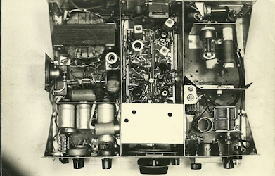
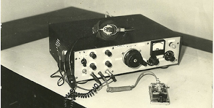
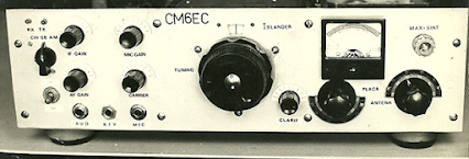
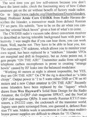
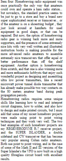
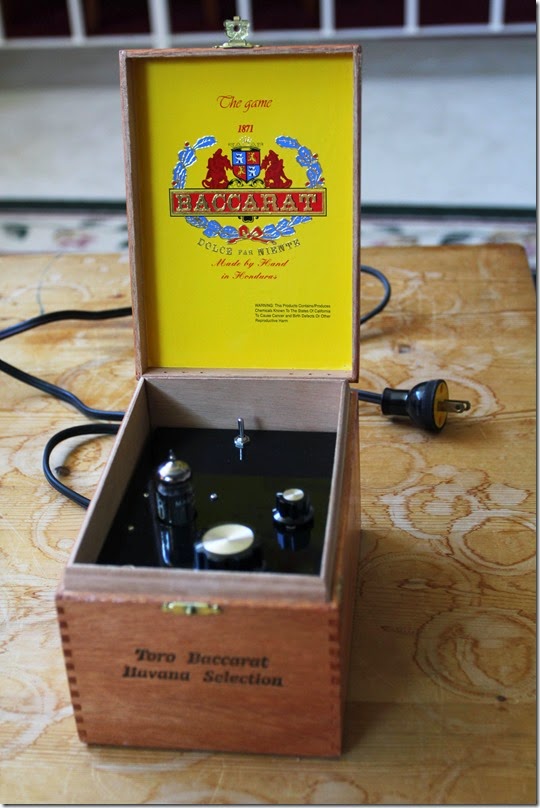
    The first Image was the prototype presented at the Ganuza meeting, the rest of the photos were the ones we built with the improvements, and the photos and plans were sent to many colleagues, the colleagues who went to that meeting will remember, well, they still have to there are many left, because that was almost 30 years ago,
    greetings CO6EC

  • (co8zz) Raul Verdecie

    Magnificent photographs!!!… They seem to have been taken today with some digital “super camera”!!!
    Really, from what I can see now, the CO6EC Islander was the perfect example… mine (my first radio and built by me) was also made like this, with the plates that the FRC sold and it was good, but very ugly …HI… The AGC worked wonderfully as it came, I don’t know if Jose’s improvements were later! With it I made my first hundred or so entities only in 40 meters / CW (between 7,100 and 7,150) when it was CL8ZZ. I gave it away so that someone would have their license and now I regret not having kept it… I would have liked to show it now to those who regret not having a radio!!!

  • (co8zz) Raul Verdecie

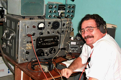
    Ah, I can never forget those headphones!!!… my external hearing aids (read ears) are much smaller today thanks to them, they exerted tons of force on the operators’ skulls!!!

  • (cm6vml) Vidal

    Very good article, I hope that one day, with a good teacher, I can build my own team, congratulations Jose, regards Vidal.

  • (co7wt) Pavel Milanes (CO7WT)

    Sure…

    My first radio and with which I got my CL7WT license back in the 90’s an ISLANDER, like that in capital letters.

    I remember that the CL only had a small 40m segment (like now) and that it was full of broadcasts as soon as the afternoon fell, it was an odyssey to speak on the radio… you had to find a “little hole” between the Broadcastings where it wouldn’t bother you ” a lot” to be able to talk.

    I remember that the old CO7OC (he is no longer a radio amateur) and CL7HU (now AC7HU) helped me build it with a board I bought at the radio club. I took almost all the valves from the deceased KRIM 218, then I found a store in Camagüey that sold idle things from the workshops…

    Turns out they had such a large inventory of “idle” tubes that they couldn’t put it on the counter…they let me through to the warehouse…huge…stack of tubes, if I remember correctly I ended up with Chinese or Japanese tubes that they were more sensitive in the receiver… the driver went from a 6P14P to a more robust 6P9, by the end that was a humble 6P44 it became two 6P7s that were a Russian version of the RCA 607 if I remember correctly… in the end it had like 80W.

    It goes without saying that when I said on the radio that there were valves in that place “they flew”….

    The VFO was the one from the Jagüey, not the original from the Islander, I never knew about the AGC modifications.

    I would like if someone has the plans with the modifications to send them to me, just for nostalgia…

    My email pavelmc@gmail.com

  • (co2jc) Carlos Alberto Santamaría González

    Brother, your article is very good, because of the nostalgia and also because it talks about what we radio amateurs like: tinkering. I didn’t have an Islander because what I started with in 2000 was a Polosa to which two colleagues helped me adapt it with VFO for 40 and 80 m. But I talked a lot with colleagues who did it with an Islander or a Jagüey and participated in the Rueda del Behique that I started in the 80 m. Others in the Hurricane Wheel that started a little later and were heard well. As you well say, the propagation at that time had nothing to do with what it is now, but it was very good to listen to the colleagues who came out with the equipment they had built. Thank you once again for your article. CO2JC

Needed: More Info on the Cuban Islander or Jaguey DSB Transceivers

CO6CBF: “I began operating on the HF bands using homebrewed radios. Mainly on CW running just 10 Watts. My very first phone transmitter was a controlled carrier AM modulator for the 160m band using tubes and components salvaged from an old TV set.”

My good friend Dean KK4DAS has built a DSB rig for 10 meters and is working a lot of DX with it. Peter Marks in Australia has also jumped into the DSB game. A few of the students we are working with at the local high school may get their General Class licenses and convert their Direct Conversion receivers to Double Sideband transceivers.

All of this has caused me to reminisce about the famous Cuban Double Sideband rigs. Homebrew Hero Arnie Coro CO2KK used to talk about these rigs on his “DXers Unlimited” program on Radio Havana Cuba. But Arnie recently passed away, and with him I think a lot of the background info on the Cuban DSB rigs has also disappeared. I find very little about these rigs on the internet — I have not been able find a single picture. The Radio Havana Cuba archive of Arnie’s shows has disappeared.

Back in February I talked to Yulian CO6YI on 20 meters about the Cuban DSB rigs. He said he had a lot of background info on them, and said he would try to send it to me. I hope he is able to do this.

The results of my initial Googling appear below. There has to be more out there. I’m thinking that there must be a lot of background info on the Islander and Jaguey rigs sitting on the hard drives of radio amateurs. It is time to give this info wider circulation. Please send me any info you have on these rigs. Of particular interest would be schematic diagrams and photos of the rigs.

https://www.paara.org/newsletter/2000/graph200007.pdf

Date: Mon, 22 Mar 2004 17:48:59 -0500 From: "Prof. Arnaldo Coro Antich"   Subject: Re: GB> 6EH7 vs. 6EJ7 as RF Amplifier  
 Dear amigo Chris: You are absolutely right ! EF184 is the best pentode for RF amplifier duty... But, let me ask you something... have you thought about the ECC88 and the even better ECC189 dual triodes that were designed for TV tuner work, and that incidentally were also about the last vacuum tubes ever designed from ""scratch"" until Phillips and other European manufacturers stopped from making receiving type vacuum tubes. The ECC189 is simply wonderful for a front end !!! I am sure that you are aware of our limitations here at my QTH regarding the possibility of obtaining solid state modern devices... so we still make ""new"" ham radio rigs using mostly vacuum tubes... We even still make a version of "" The Islander"" a DSB transceiver with direct conversion vacuum tube receiver... Tube lineup is EF184 RF amp ECH81 product detector ECH81 triode section not used ECL82 triode audio preamp ECL82 pentode audio output 6AH6 VFO ( Russian equivalent 6*5P ) Audio filter provided by good working brain of operator !!! Keep up the good work amigo !!! 73 and DX YOur friend in Havana Arnie Coro
CO2KK

http://ibiblio.org/modena/GLOWBUGSpiobaire/glowbugs.piobaire.weekly.html

Today’s first question came from a long time listener in India. Rajiv tells me that at this moment he is not able to pick up our station on the shortwave bands, and he rightly assumes that this is because of the very low solar activity… but Rajiv who lives in the garden city of India, Bangalore, the home of the nation’s electronic and other high tech industries, is able to read the scripts of the program that are made available to several short wave listeners clubs e-mail distribution lists. Rajiv tells me that he wants to obtain the electronic files of the Super Islander amateur radio transceiver to compare the circuit diagrams and design philosophy with a similar project that is becoming very popular among Indian radio amateurs. Ok amigo Rajiv… I have already sent you all the files including some nice digital photos of the first prototype of the Super Islander, that as you will see, has two final amplifier options , one built using NPN RF power transistors, and the other one using two vacuum tubes that are very easy to find here in Cuba from recycled TV sets. The Super Islander is a single band transceiver that can be built for the 160, 80 or 40 meter bands. Here in Cuba amigo Rajiv, the most popular amateur band nowadays is two meters, using the FM narrowband mode, and the second most popular band among Cuban radio amateurs is 40 meters, that’s why most of the Super Islanders are built for operating between 7.000 and 7.150 kiloHertz. The double sideband signal generated by the Super Islander simple circuit is very stable, and very few if any radio amateurs that contact stations using the Super Islander are able to detect that it is a double side band and not a single side band signal what they are hearing. One of the most outstanding features of the Super Islander single band amateur radio transceiver is that it is modular, so those who want to build it, are able to build and test each module as a single project, and after all the modules are fully tested, then they are easily wired together . The parts count, that is the number of components required to build a Super Islander was kept intentionally as low as possible, both to simplify its construction and to increase the reliability. I hope that amigo Rajiv in Bangolore , India will be able to make good use of the Super Islander’s files, and maybe even go ahead and build one , as the parts required are almost universally available, because that was one of the design requirements that I set when starting the Super Islander project more than fifteen years ago….You can learn more about this simple amateur band transceiver by sending a request for the Super Islander files to arnie@xxxxxx … I will send it as a dot zip file and you will be able to see circuit diagrams, photos and full descriptions of the different modules of this nice little rig, that has proven itself under the most difficult circumstances, like handling emergency communications links during tropical storms.
http://www.hard-core-dx.com/hard-core-dx/2007/msg02587.html


Beginners generally build one of two radios; the vacuum tube Islander or the solid state Jaguey. The Islander is a DSB/CW Cuban design using a very clever low parts count circuit and a direct conversion receiver. The Jaguey, named for the Jaguey Grande Radio Club in Matanzas province, is a generic design, with a DC receiver, DSB and CW, using solid-state components. Many of its ideas are from Wes Hayward's W7ZOI's Solid State Design for the Radio Amateur. The lack of mechanical filters or quartz crystals to homebrew SSB filters made Cuban designers CO5GV, CO2JA and CO2KK choose a DSB and CW rig. Fitted with good quality capacitors for the VFO, it works quite well from a 12-volt car battery in hurricane emergencies.

Arnie Coro CO2KK — Homebrew Hero — Silent Key

I was sorry to read this morning of the passing of Homebrew Hero Arnie Coro CO2KK. As we see in one of the obits, Arnie got his start in radio at age 12, with the gift from his father of a chunk of galena, a coil, and some headphones.

Here are some of the SolderSmoke posts about Arnie:

https://soldersmoke.blogspot.com/search?q=CO2KK

He will be missed.

International Brotherhood and the BITX Rigs

Bore and Heriberto’s uBITX board

Nowhere is the International Brotherhood of Electronic Wizards more evident than in the work on the rigs designed by Farhan. With the BITXs we see rigs designed in India that are now being built and modified all over the planet. Here are just a few examples of the global collaboration currently underway:

In Italy, Giuseppe is putting a BTX40 on 20 meters and making it a dual bander:

Hi everyone, I just completed some tests on a Bitx40 running in 20 meters band. I addes the 20 as secondary band activate when needed. I apply some mods to switch to secondary QRPLab BPF filter centered to 20 meters and removed the C91 and C92 caps to work in USB. I done some RX tests in the weekend of iaru hf contest to listen some stations Active.
Here the issues registered:
1) the 20 RX sensitivity was a bit weak compared to 40 meters. I need to increase volume. ( To receive the 20 meters the vfo run to 26 MHZ, mybe some stage suffers of poor performance in this High frequency?)
I also tryed to increase the vfo over maximum allowed by raduino, using external buffer, but no results.
Please read the issues as: work but could work better!
2) the RX was not very clean: voice acceptable, but RX of Digital mode not very stable ( probably the cause could be the vfo shift for poor tuning control. I need to add lock function in firmware …) Or interferences for free wire of connection.
3) Sometimes when switch on or change vfo to other band or mode, the bf amplifier start a self oscillation …Resulting in my wife’s screaming (the tests were also performed during the night!)
No tests was performed at the moment in TX because i need to install the LPF for the new band.
The firmware to make the test was a modified version of 1.17.1, few temporary mods to preset the vfo b to 14 MHz USB and correct the freq. Display.
These my tests.
Giuseppe Callipo IK8YFW.
Pavel is a young fellow in Cuba who is doing great things with the Raduino software:

My Photo

Hi to all.
The code was updated, the change log is this:
v1.4Update to catch up with the features added in the Raduino v1.17.1 from Allard’s code (CW SPOT and bug fixes)
  • Upgraded the operations instructions
    • More user friendly version with embedded images.
    • Add instructions for the S-meter, AGC and TX-power mods details and tricks.
  • Moved all images to its own folder “images”.

As usual tips/bugs/comments/suggestions are welcomed, you can reach the code here: https://github.com/pavelmc/bitx40/

There is a inoffensive bug in the calibrate process, in which the actual calibrate value is not correctly showed in the LCD until you move the pot to adjust it, I’m working on it.
I’m slowly working in this direction now:
  • Bug removal in the calibrate function.
  • Finish the upgrade of the Si5351mcu lib with some improvements.
  • Adding CAT support via ft857d lib (https://github.com/pavelmc/ft857d):
    • Full compliance needs get rid of all the blocking delay() sentences and that need a structural/paradigm code change and a lot of testing (I have Fldigi/MixW/Hamlib to test, I think if that 3 works the rest will do it)
    • Moving to a library (yatuli: https://github.com/pavelmc/yatuli) for the pot usage, that will ease the process of implementing the CAT as almost all delay() calls are related to pot/clicks, so I’m on it.
    • Maybe implement a multiclick lib to optimize the code and make it more easy to understand.
Any thoughts or whishes related to that?

I plan to make the CAT operation optional via a #define declaration as not all of us will/want-to use that.
73 Pavel CO7WT


Here we see Bore in Montenegro working on a uBITX designed in Cuba by OM Heriberto

Hi Colleagues
Bore Lezaic from Montenegro is working on the uBitx PCB designed by Heriberto -CM2KMK- from Havana, Cuba
Here some pictures he(Bore Lezaic) have posted in my FB wall.
Any question regarding uBitx PCB please send to Heriberto Gonzalez Mendoza at cl2kmk@frcuba.cu (please take care with the email address it is slight different to his actual call sign).
Qrv’s
73’s Jc

Bore and Heriberto’s Board

Hidehiko in Japan was struggling with some LCD noise in his experimental BITX40. I passed along the active filter circuit that I’d first seen in Roy Lewallen’s Optimized QRP rig.

To
BITX20@groups.io Jul 29 2017 at 4:22 AM I’ve finished the Bitx40 experimental project today. I added the AF-AGC and LM386 POP limitter with raduino v1.20.1 (Thanks Allard). And I also added the DuinoVOX for Digital Mode operation. It’s a great radio but the problem is only the “LCD noise” when increasing the AF volume. hi… Can I reduce this noise? Or I have to use the analog VFO? Any suggestions welcome.
ja9mat Hidehiko
To Hidehiko JA9MAT:
Very simple. Just three parts. NPN transistor (like a 2N3904) and a 47k resistor (collector to base) 100 uF cap (base to ground). Vcc the collector. Emitter goes to the DC power input of the AF amplifier. You can see my use of this circuit in the schematic in this blog post:
Look in the lower right, near the LM386 AF amplifier. Click on the schematic to enlarge. 73 Bill N2CQR
Thanks Bill,
Well I added “3-parts”(2N3904+47kohm+100uF) between the D18(1N4148) and the junction of R111(100ohm) and R1113(220ohm). The noise has absolutely gone!
ja9mat Hidehiko.

_._,_._,_

Tube Transmitter in a Cuban Cigar Box

Beautiful use of a cigar box by Ben, KK6FUT. Ben is working in close proximity to Pete N6QW and has obviously fallen under the influence of Pete’s “Build Something With Tubes” field.
Watch out for the high voltage Ben. You aren’t in Arduino-land anymore! One hand behind the back OM!

Our book: “SolderSmoke — Global Adventures in Wireless Electronics” http://soldersmoke.com/book.htm Our coffee mugs, T-Shirts, bumper stickers: http://www.cafepress.com/SolderSmoke Our Book Store: http://astore.amazon.com/contracross-20

Radio China International Echo Mystery SOLVED!

For the past month or so I have been wondering about a strange echo that I’ve been hearing on the 31 meter transmissions of Radio China International. I first noticed it on my “Kings Speech” regen receiver. Then I heard it again on my “Off the Shelf” regen.

For a while I thought that what I was hearing was a propagation effect: Perhaps the very strong RCI relay station in Quivican,Cuba was sending north a signal so strong that it was travelling around the earth along the grey line and coming back to me about .133 seconds after the original reception.

This sounded plausible (and it does happen sometimes). But there were reasons for skepticism: Why wasn’t anyone else hearing this? Why wasn’t the effect showing up on signals from Radio Havana Cuba?

Pete Juliano had suggested that perhaps I was getting signals from TWO different RCI transmitters. I had quickly checked the RCI schedule and didn’t see them transmitting on the same frequency at the same time from multiple transmitters, so I kind of put that idea aside. Hey, the round-the-world idea was just more appealing!

But then I remembered something strange about the echo: It seemed to disappear when I tuned close to the center frequency of the RCI signal, but then appeared when I tuned off to one side. Hmm…. That was an important clue.

I’ve long been wary of regen receivers and for a while suspected that I was dealing with some weird regen effect. Regen and Echo seem to go together, right? Well, as it turns out, no. But I was right about this being an effect of the nature of my receiver…

Last night I was listening to RCI English service at around 0030 UTC on 9570 kHz. Nice clear signal. No echo.

At 0100 UTC the program changed, and the echo started. A very strong echo.

I went to the RCI schedule. Here I found the answer:

At 0030 they were transmitting from their relay station in Cerrik, Albania on 9570 kHz.
At 0010 they switched programs, frequencies and transmitters. At 0100 Cerrik shut down, but the Quivican, Cuba relay came on on 9580 kHz. At the same time the RCI transmitter in Kasi Sabagh in far-off exotic Western China, in Xinjiang, fired up on 9535 kHz. Both transmitters were carrying the RCI English service.

You see, my little regens are not very selective, and the RCI transmissions are quite strong. So if I have my receiver tuned to around 9560 kHz, I’ll be hearing BOTH the signal from Cuba AND the signal from Xinjiang. That would explain the echo.

To try to confirm this, last night I fired up my old Hammarlund HQ-100 receiver to see if I could discern the two different signals. I could. And the echo appeared when I tuned BETWEEN the two. You can hear this in the video above.

There is one remaining question here: Is the echo caused by the RADIO path difference between the two transmitters? Or are we just seeing the effect of the programming being transmitted at slightly different times, perhaps with this delay caused by INTERNET latency? Anyone know how RCI gets its signals from its Beijing studio to its distant transmitters? I calculate that the path difference is about 10,000 km. With c at 300,000 km/second, that would yield an echo of only about .03 seconds. The echo we are hearing sounds longer than that, so I suspect we are hearing a difference in studio-transmitter transmission time. What say the SWL RF gurus?

BTW: I think the same phenomenon may explain the echo on Brother Stair’s “Overcomer” signal. I see that starting at 2200 UTC he is on BOTH 7570 kHz and 7730 kHz from RMI transmitters in Florida. Perhaps they are not synched up.

I think this is all very cool. Think about it: Here I am, sitting in Virginia in 2014, listening to the Albanian, Cuban, and Xinjiang relay stations of Radio China International on a receiver first built by some guy in England during the 1930s. And I’m trying to figure out if the echo I hear is caused by the limits imposed by the speed of light and the size of the earth, or by the time it takes packets to move through sub-oceanic fiber optic cables.

Our book: “SolderSmoke — Global Adventures in Wireless Electronics” http://soldersmoke.com/book.htm Our coffee mugs, T-Shirts, bumper stickers: http://www.cafepress.com/SolderSmoke Our Book Store: http://astore.amazon.com/contracross-20

Regen Receivers in Cuba

Hola amigo Bill:

I was able to pick up the podcast with excellent audio quality.
It is quite true that regenerative receivers are very much in use
even today… for example many if not all of the automobile RF
keys opening and closing the cars doors rely on a superregenerative
receiver circuit !!!

The radio that you copied at the blog works very well indeed
but it would be good idea to include a 5 kilo ohms volume
control…. Very easy to do indeed.

But let me tell you that my favorite regenerative receivers are
the classic ones, using vacuum tubes, and operating them
at voltages not higher than 50 volts… As a matter of fact many
tubes work very well at the 24 volts DC voltage level.
Using the classic Hartley circuit , there is no need for a hard to
find throttle capacitor required by the Armstrong circuit, because
the regeneration control works very well by using a potentiometer
to change the screen grid voltage of the detector.

I agree that using an RF stage ahead of the detector is always
a very good idea…. In my tubes regenerative I use a triode connected
6AK5 clone…. as a grounded grid stage….another 6AK5 clone ( the
6ZHE1P Russian tube ) is the detector and I use another 6AK5 clone
as the first audio amplifier then feeding an audio output pentode
all provided from a very simple basic 70 volts DC power supply.
BTW, using regulated DC on the filaments of the detector stage,
although a luxury by my standards is very helpful to reduce
hum …. 7805 regulator recycled from a bad motherboard, with
one 1N4007 from broken Compact Fluorescent Lightbulb inserted
in series with the regulator ground pin, produces a nice 5.7 volts
regulated DC that with a brand new tube is more than enough… with old
6ZHE1P recycled from Russian TV sets, you add another 1N4007 to obtain
6.4 volts regulated DC….

As said in the podcast, it is very important to do a very good
mechanical engineering job, place the main and bandspread tuning capacitors
away from the front panel, use isolated shafts between the capacitors
and the dial mechanism and make the front panel of a a thick steel
plate if possible.

There is a Dutch Cascode Regenerative radio that several Cuban radio
amateurs have built… it was designed with the amateur bands in mind so
the information about the tuning coils and capacitors lets you
obtain a very excellent bandspread on the ham bands.
I can send you that circuit that uses very common 12AT7-ECC81
and Russian equivalent double triodes.

Keep up the good work amigo and always tell us when the next
podcast is available. BTW it lasted for almost an hour !!!

73 and DX

Your amigo en La Habana, Cuba
Arnie Coro
CO2KK
Host of Dxers Unlimited radio hobby program
Radio Havana Cuba

Our book: “SolderSmoke — Global Adventures in Wireless Electronics” http://soldersmoke.com/book.htm Our coffee mugs, T-Shirts, bumper stickers: http://www.cafepress.com/SolderSmoke Our Book Store: http://astore.amazon.com/contracross-20