Get Frank’s book here (FREE!) http://www.qsl.net/k0iye/
I’ve had Frank’s book on the blog many times over the years, but it is a book that merits repeated mention. It is filled with great advice and homebrew wisdom. I found myself looking at it again recently, and at Frank’s QRZ.com page. I came across lots of wisdom that I may have missed in earlier visits. For example:
From the QRZ page:
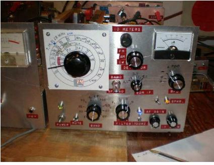
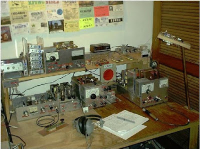
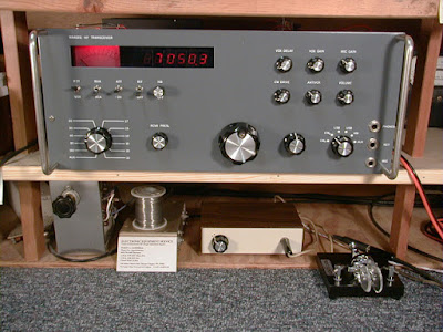
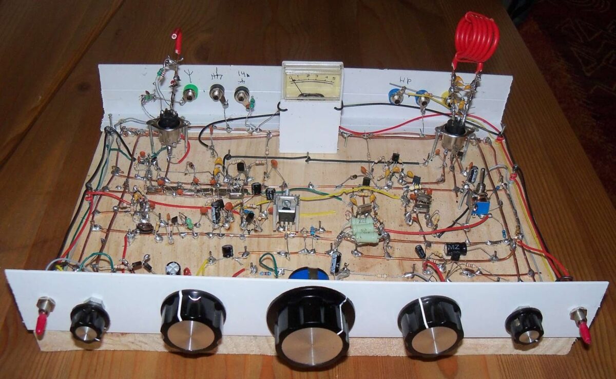
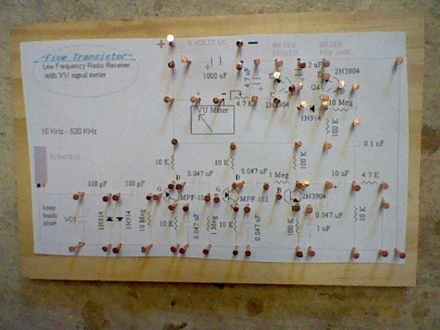
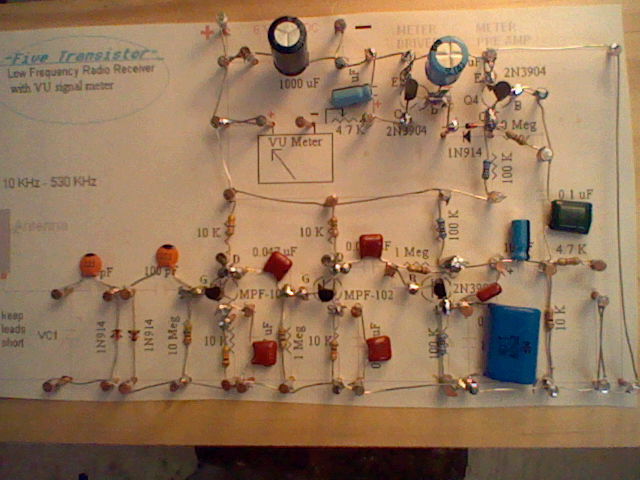
My version of ham radio is 100% scratch built equipment. I buy nothing manufactured for ham radio except log books…My rig is based mostly on the 1986 ARRL handbook. Modern designs in today’s QEX and Handbooks are usually full of mysterious ICs. In my opinion, they don’t qualify as homebrewing.
From his book (Chapter 15):
I was fascinated by ham radio, but I didn’t learn much about how sideband worked. I had the impression that sideband was MODULATION FOR MILLIONAIRES and too complicated to homebrew. The 1957 ARRL handbook’s opaque descriptions of “phase shifters” and “balanced modulators” only confirmed my opinion.
If you are like me, you will have a devil of a time getting your SSB drivers to produce intelligible speech without hissing and noise problems. All I can tell you is to keep your brain mulling over your difficulties. Shield and filter your prototype until the darn thing works. Keep careful notes so you don’t make the same mistakes twice. Persistence will win in the end.
My sideband transmitters are still in the experimental category. You will find that it takes a great deal of tweaking and fussing to get SSB tuned so it sounds good and doesn’t radiate on unplanned frequencies. You won’t believe how many diseases your SSB transmitter will create for you to conquer! Sideband is not a project for impatient people.
Foreword:
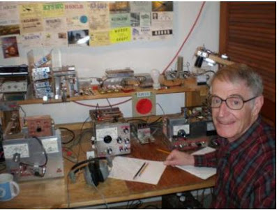
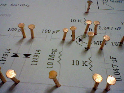
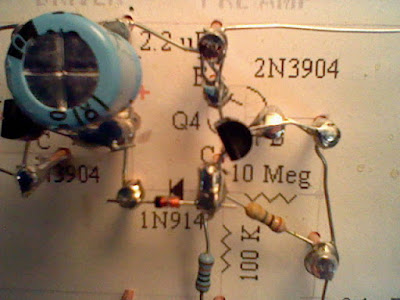
We homebrewers are nearly extinct, but there are still hundreds of us scattered around the world, some are even in the USA. Yes, there ARE American homebuilders! We’re rare, but thanks to the QRP hobby, the number is growing. Even if we homebrewers don’t change the world, I guarantee you will enjoy learning radio technology and building your own equipment.
Get Frank’s book here (FREE!) http://www.qsl.net/k0iye/
THANKS FRANK! Send Frank a thank you note: Frwharris@live.com