A Good Radio Morning at N2CQR

The Radio Gods were smiling upon me this morning. I started out on 17 meters and had three nice contacts with European stations: OH5CZ, a young fellow near Helsinki; HB8DQL; then RM2D in Moscow. FB.

Then Pete showed up on the Skype. As he has said on his blog, he is still struggling with a family medical emergency, but I am happy to report that he is coping well, making good use of his can-do project manager background and his good sense of humor. It was great to see him.

Inspired by my talk with Pete, with 40 meter AM playing in the background, I turned to my R2 FRANKENSTEIN phasing receiver. Last night I completed the 90 degree phase shift network. This is built around two quad op-amp chips and is designed to take the audio output from the two DC receivers and create a 90 degree phase difference between them. I tested this stage by sending the same audio into each set of op amps. I then put one scope probe in the output of one chain of op amps, and the other probe on the output on the other chain. Wow. Bingo. 90 degrees of phase shift across the 300 — 3000 Hz audio spectrum.

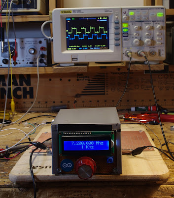
Emboldened by this positive result, I put the completed stages together this morning. They passed the smoke test. Then I tuned to 40 meters. Wow again! As promised, opposite sideband rejection without resort to crystal filters. But as luck would have it, I ended up with a configuration that suppressed the Lower Sideband. For 40 meters, obviously I needed to suppress the other side of zero beat. But all I had to do to remedy this was to reach into the DDS box and switch the I and Q jumpers on the M0XPD/Kanga UK Arduino AD9850 shield. This switch put me on LSB. Very cool.

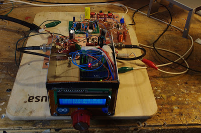
Here is a view from above:

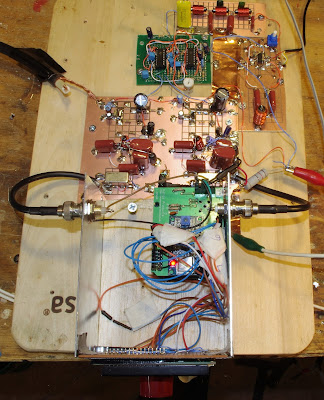
The AD9850/Arduino DDS box is in the bottom center. Above that, near the center of the picture, is the board (from N6QW) with the two SBL-1 mixers and the initial AF amp stages. The small green board above that is the IC phase shift network. At the top of the picture you see the 3000 Hz low pass filter. Below that, the board with the little blue pot has an IC AF amplifier and a 300 HZ high pass filter.

I still have to build the audio amplifiers prescribed by the designer, Rick Campbell KK7B. But obviously I am already having a lot of fun with phasing. Here is the QST article on Rick Campbell’s R2 receiver:
https://www.arrl.org/files/file/Technology/tis/info/pdf/9301032.pdf

New Rig: The FRANKENSTEIN Phasing Receiver

Here is my latest project. I call it The Frankenstein because of the two BNC connectors that come off the side of the DDS oscillator box — they look to me like the bolts on Frankenstein’s neck. The square waves from the DDS LO also seemed to evoke Frank’s bolts. There may be other similarities. We’ll see.

Here is the idea: Phasing, Direct Conversion, Image Rejecting receiver based largely on the R2 design by Rick Campbell KK7B as presented in the January 1993 QST.

I’m using an AD9850 with an M0XPD Kanga board and an Arduino to generate the quadrature LO signals (you can see the square waves on the ‘scope in the background). I’m using the software of Richard AD7C; this, combined with the divide-by-4 scheme on the Kanga board, puts the upper limit of reception at 7.3 MHz. That’s OK for now.

When I first fired up my AD9850 box I was dismayed to find that the square wave quadrature output was no longer there. I was about to give up and get anther shield board, but this kind of surrender bothered me. So I started troubleshooting and isolated the problem to the /4 chips. My soldering of the surface mount chips was, well, a bit dodgy, so I changed to a tiny soldering tip and reheated all those tiny little pads. Hooray! I fixed it.

The receiver will be built mostly on a PC board that Pete made for me back when he was trying to convince me to build a fourth BITX receiver. I am pleased to put the board to use. See below.

Yesterday I soldered on the two SBL-1 mixers that will form the heart of this receiver. I realized that the very robust quadrature square waves from the Kanga board might be robust enough to fry the sensitive little SBL-1s. Sure enough, I measured about 17 dbm coming out of the Kanga board. I threw together two roughly 10 db resistive pads. These should prevent the SBL-1s from releasing their smoke.

I hope this receiver will be four receivers in one:

1) Standard DC receiver.

2) Binaural Receiver! Groovy, stereo CW that floats around in your head, man!

3) I-Q receiver that can be fed into the sound card of the computer for DSP, panoramic display, etc. I promise not use it to find fault with the signals of homebrew SSB rigs.

4) SSB image rejecting receiver for easy, Direct Conversion SSB listening without the burden of having to listen to the other side of zero beat.

There is already a lot of soul in this new machine: Kanga board with the design my Paul M0XPD, PC board made on Pete’s $250,000 CNC machine, and all of it on an actual breadboard (from Italy, I think).

Rick Campbell and Peter Parker have commented on the allure of phasing rigs. There is something very attractive about them. There is a cleverness in the way this design exploits the phase relationships between sidebands to allow us to null out the unwanted side of zero beat. It took me a while to really understand how this is done — once I understood it, I really wanted to build a rig that would make use of this principle.

A Good Old VFO (by Rick, KK7B)

Here is another really great message from Rick, KK7B, sent to the emrfd yahoo group: [emrfd] A Good Old VFO Saturday, August 22, 2009 10:29 PM From: Rick To: emrfd@yahoogroups.com For several critical receiver applications in my lab I’ve used old Collins PTOs converted to solid state (I just replace the triode in the classic Hartley circuit with a J310 and run the circuit from a 9 volt regulator). I have half a dozen of them in dedicated propagation study receivers, and one SSB exciter I occasionally use on UHF. The other day I was changing something else in one of my receivers and connected the solid-state PTO to the frequency counter on my bench. The PTO was set to 3.100000 MHz. From a cold start (it hadn’t been turned on for years) it drifted three Hz over the first ten minutes, and then a total of 10 Hz over the next few hours. When I calibrated one of my 144 MHz propagation study receivers 25 years ago, total frequency drift was <18Hz/hour. I expect most of that was aging of the overtone crystal oscillator in the premix circuit. Old Collins PTOs are common (someone at Dayton this year had a box of unknown ones in decent shape for $10 each, and there are R390 PTOs in the current Fair Radio flyer). I've never had one fail, tuning resolution is infinite, phase noise is low, digital noise is zero, and once I build one into a receiver, that part of the project is done--no improvements, software upgrades, needed. My research receivers are connected to a baseband Fourier analyzer (yes...even 25 years ago). The finest resolution I've used for serious experiments is 10 milliHertz, but more often I use 1 Hz resolution, with 1024 channels in the output spectrum. I often average spectra for more than a minute, so frequency drift needs to be less than 1 Hz per minute. The solid-state Collins PTO is much more stable than needed even for those critical experiments. This is not a fluke. Every Collins PTO I've converted to solid state using a U310 or J310 has had similar performance. Sometimes it is useful to remember that the major benefit of digital frequency synthesis is that it is quick, cheap, and frequency agile. No commercial manufacturer could afford to build a transceiver with a Collins Mil-Spec PTO in it these days. But for an amateur with mechanical skills or access to surplus hardware who needs just one good oscillator, the venerable Hartley with a temperature compensated tuned circuit and a JFET can provide outstanding performance. In music, art, architecture, automobiles, motorcycles. .. there are recognized "golden eras" where some combination of factors resulted in technical hardware that is widely recognized as being superior to what is being produced today. Often the difference is directly related to the amount of skilled labor needed during production. As technical hobbyists, we automatically assume that new is better, but as experimenters, we should be open to the idea that sometimes the technology, ideas, and block diagrams of an earlier era are superior to the cost-driven disposable technology coming off fully automatic assembly lines in some out-of-the-way place with inexpensive labor and attractive business tax codes. The idea that old technology designed decades ago by retired guys might be better than new technology is a radical concept in electronics. But NASA is using a brand new, hand built, Traveling Wave vacuum tube in the current Moon exploration mission. After 100 years of radio experiments- -it is fun to look back and find old technology that might actually work better than some of the new things we've been inventing recently. Best Regards, Rick KK7B

Thoughts on Minimalist Radio

I had a lot of good articles on the old web-page version of this blog. I want to get them into the index, and the only way I can think of to do this is by posting them again. I don’t think this is a problem: many readers will have never seen them, and even for those who have, many of these are so good they deserve a second look. This 2006 piece by KK7B is a good example (The picture is from Roger, KA7EXM’s FDIM 2007 photo collection and shows KK7B winning a toroid winding contest):

A FEW THOUGHTS ON MINIMALIST RADIO FROM KK7B
(Originally posted on the EMRFD Yahoo group)

If you really want to do minimalist radio, you may want to step way
back and take a look at some very early history. The Pixie circuit
has many more components than an early CW station from the era
immediately after spark.

Rather than starting with the Pixie and trying to figure out what to
eliminate, maybe a better approach is to start from zero and decide
what you need. Combining transmit and receive functions is the last
thing to think about.

Starting with the receiver…. The first thing you need is wire up
in the air. The more, the better. If you have the real estate for a
full sized dipole on 80 meters, you can collect enough signal energy
to hear on a crystal set when conditions are good. I’ve copied CW
signals on 40 meters with just a dipole, transmatch, a 1N34 diode, a
good pair of headphones, and a one transistor Pierce oscillator
running on the bench. The leakage from the crystal oscillator picked
up by the antenna beats against the incoming signals. I didn’t power
the oscillator with lemon juice, but I could have (see Bob Culter and
Wes Hayward, “Lemonized QSO” in March 1992 QST.)

Then for the transmitter, just heat-sink the Pierce oscillator and
key the connection to the load. The shift in load impedance will
offset the crystal oscillator frequency.

A dual pi-net transmatch configuration would take care of the
harmonics and allow maximum energy transfer between the antenna and
diode–but I’d analyze it to make sure the harmonic suppression is
more than legal.

So far I count 5 components for the dual Pi-Net transmatch, a 1N34
diode, 6 components for the one-transistor Pierce oscillator. A
dozen parts, plus headphones, a key, and battery–or some electrodes
to push into a lemon.

That would make contacts, but Wes and I have discussed a basic rule
for radios, which is that a station should be able to work an
identical station over a distance of a few miles. It could probably
be done with the above station, but a single transistor audio
amplifier running at maximum gain between the 1N34 and headphones
would make it possible to extract many more signals from the 80 meter
dipole. That’s another 5 or 6 parts. So now I’m up to about 20.

For a more serious station, I’d probably add two more transistors and
a diode, so I could have a separate PA, a balanced mixer, and two
audio stages. The receiver would end up looking a bit like EMRFD
figure 8.7 with a PA tacked on. That would have about 35 parts, but
it would be able to work DX off the ionosphere…about the same
complexity and performance as many other variations on the theme. A
previous version of the Pixie from the 1970s was called “The
Optimist.”

Unlike Muntz–instead of starting with someone else’s circuit and
trying to eliminate parts until I had something that just barely
works, I’d start from scratch, study EMRFD (and other references too–
but in EMRFD all the circuits have been designed and tested) for
circuit ideas, and then start experimenting on the bench, one stage
and one component at a time. Since one of the joys of minimalist
radios is that they can be understood all the way down to the device
physics, I avoid ICs. (I particularly avoid cell-phone ICs, which I
designed for a number of years. It’s like working in a sausage
factory–you are much happier if you don’t know what’s inside.)

Minimalist radio is one of the more interesting design games that we
play using the methods of EMRFD. It’s cheap, it’s interesting…and
as we dig in, we discover that the details can be every bit as
challenging for a radio project with 30 parts as one with 30,000.

Have fun.

Best Regards,

Rick kk7b