Writing to the BITX e-mail group, Farhan provides some very interesting information on the philosophy behind his new BITX 40 module, and on how it differs from earlier BITX designs:
The new builders are often caught in a catch-22 : to get on air they need to build a rig from scratch. but to build a rig, they need lots of experience. A way out was to provide working boards where we can get on air quickly, and then start improving and modding the circuit. this is the spirit behind the new boards. Consider them like you would consider a raspberry pi or an arduino : simple, working circuits around which you can grow your own radio.
In the new bitx boards, I have tried to keep as close to the original bitx as I could. however, there are a few departures that I thought the bitx builders here would like to know about.
i have to admit though, strangely, i am less familiar here with bitx than many others on this form. arv, leonard, dan, andy and others have build far many more version than I did. I just happen to be the first one to build a bitx. this as much an acknowledgement of their inputs. without all you folks, bitx would not have had the kind of traction that it now enjoys. I suspect that it is the most built transceiver in the world.
So, here are the changes from the original bitx.
1. SMD
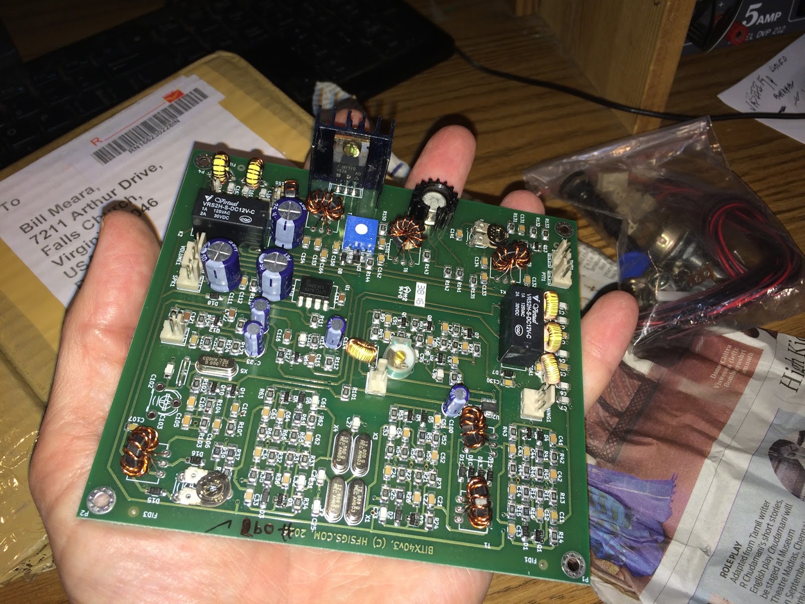
The SMD components make for virtually error free boards assembly. We used the biggest sized SMD components. In fact, the resistors and capacitors are about the same size as a quarter watt resistor that is soldered standing up. They are very easy to desolder without messing around with the desoldering wick and solder pumps. All you do is to lay the soldering iron’s bit on the component such that the flat end touches both sides at once and after a few seconds just drag the component away. I soldered the sample boards with my regular, 2 dollar, 25 watts iron without using a magnifier (I wear reading glasses).
1. 40 Meters
It is just that with the sunspots fading away, 20 meters in the tropics is far less active than before. Many of the us South Indian hams hang out on the lower end of 40 meters every morning and evening. Hence, the choice. That doesn’t mean that i can’t be converted to 20m! There are several ways to change to 20 meters. Keeping the VFO same, change the crystals (and hence the IF) to 8.833 MHz and rework the band pass and the low pass filters. I will work out the details in a few weeks and post them here.
2. A new bandpass filter
The original bandpass filter was quite lossy. I didn’t know how to use any CAD tools when i sketched it. I was actually on a long haul flight when I designed that filter. The new filter configuration is very interesting one. I saw it on PA3AKE’s site. This is a triple tuned circuit with very good out of band attenuation while maintaining very low loss.
In the last then years, ecomm has made it possible for us to globally access good quality toroids anywhere in the world. Hence, we have used T30-6 toroids with excellent low loss. I measured it at just 2 db, the original had more than 6db loss.
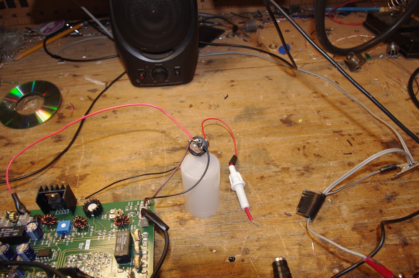
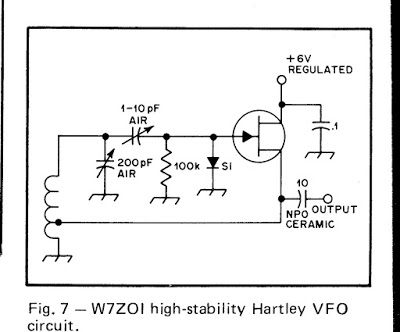
3. VCO
The original oscillator on the BITX used a variable capacitor. These were noisy, and often of inferior quality. In any case, they are no longer available. Instead, we have used a varactor diode for tuning. The greater benefit of using a varactor to tune the oscillator is that the tuning control only carries a DC voltage. You can install it anywhere. If you need finer tuning control, you can add a second lower value tuning pot in series with the main tuning pot. It is easier to add FLL to a VCO.
4. Audio muting
The original BITX used just a switch to move from receive to transmit. The receive voltage charged receiver’s audio preamp’s decoupling capacitor and it took time to discharge. this kept the audio preamp active even on transmit and caused a very sharp audio noise on the transmit change over. Now, the other section of the T/R relay is used to cut the audio off to the LM386 as soon as transmit line is energized.
5. A better T/R system
The original bitx didn’t have a PTT. this one has two relays to switch the linear amplification chain in and out of the circuit, mute the audio and change over the antenna. These changes lead to a very stable linear amplifier and smoother change over.
6. Mic amplifier
The original mic amplifier easily saturated. The new design, thanks to dan tayloe, has a better head room and provides very clean modulation.
7. The fixed BFO
Though the PCB has the provision for a trimmer and an inductor to pull the crystal frequency. I discovered that with five matched crystals, if you used 4 in the ladder filter, the fifth’s frequency fell right into the perfect sweet spot for LSB work. You might need to add the trimmer and an inductor back for USB work.
8. DDS connector
To use the DDS, you will have to remove L4 (the VFO inductor) and inject the DDS/PLL output into the connector provided.
There are some smaller mods that people can try out:
* The current in the receive amplifiers can be reduced if you don’t have any radio hams in your neighbourhood who run kilowatt amps.
* The capacitor between pins 1 and 8 of the LM386 can be removed if you prefer headphones to speakers.