This was very cool. I got on 40 SSB this afternoon with my trusty Digi-Tia. I heard a station saying he was running 5 watts… Hmm, could that be a BITX40? Indeed it was. And it was the Peppermint Bark BITX 40 of Bruce KC1FSZ that we featured a few weeks ago. He was up in Boston. K3MY was kind enough to let us have the frequency. Bruce and I had a nice contact. He told me he is working on a completely scratch-built BITX. FB. TRGHS.
Fred’s idea really resonated with me. My first SSB rig was an HW-32A, the 20 meter version of the rig shown above. If — as I suspect — these rigs are anything like the HW-101, they are not aging well. Heath’s drive for economy resulted in rigs that don’t hold up to well over time. I remember the sound of the plastic HW-101 dial clutch cracking when I pushed the button. BITX40 Modules to the rescue! Put a mono-band board inside an old mono-band rig. There are a lot of possibility here. Some ideas: — Put that Heath VFO to use. Maybe convert it to solid state. Or just put the LCD from an Si5351 in the window (Pete did this with an HW-101). — Get the S-Meter wiggling. — Keep the final amplifier circuitry in there and let the BITX drive it. This will give you a QRO option. (Uh oh, we’re in trouble again!)
Hello Fellows,
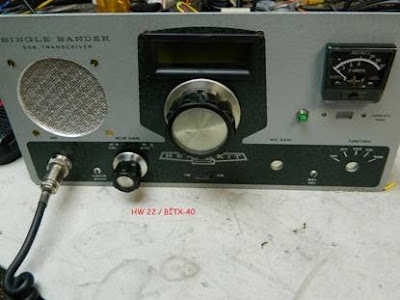
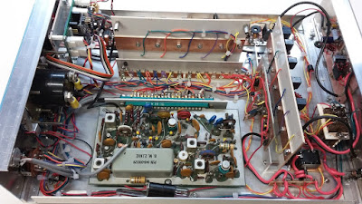
Attached is a picture of my BITX-40 V3 adapted to a Heath kit Single Bander HW22. This is a work in progress but what a neat way to bring an old boat anchor into the present.
The only parts of the HW 22 used were the front panel and case and knobs. Modifications yet to be incorporated include: AGC , a USB port on the front panel to access the Arduino, and a PTT/CW mode switch.
I enjoy your pod cast and web site…Best of 73 KC5RT.
Can’t say enough good things about your podcast – thanks for all that you do. I’m a fairly new ham and have been trying to go the home-brew route as much as possible.
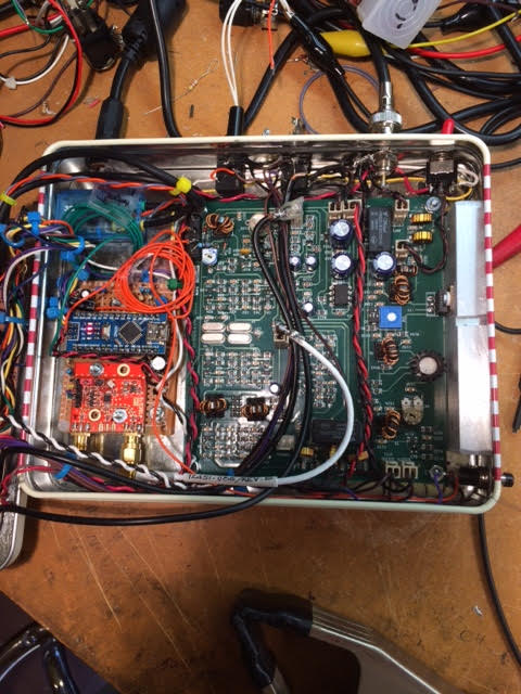
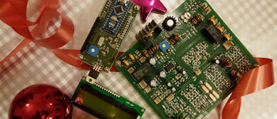
I bought a BITX40 module (pre Raduino vintage) and added my own VFO board using the usual parts. Actually, I’m using a Teensy 3.2 instead of an Arduino because it is a faster part and has a lot of DSP functions built into it that I’m using for digital mode stuff. But it’s the same basic idea.
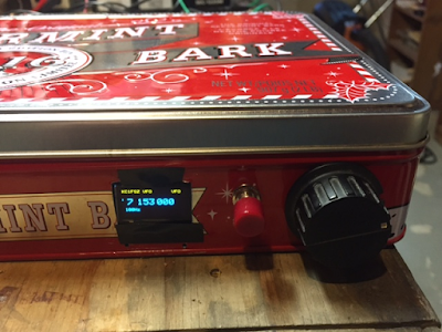
My BITX40 is not as photogenic as some of the others, but I sent a picture below. This is the “biscuit tin” variety. It’s was funny actually: a co-worker of mine stopped by my office around Christmas to give me a gift and pulled out of his bag a very nice box of “peppermint bark” candies with a ribbon around it. The VERY FIRST thing that crossed my mind the instant I saw the gift was …. BITX40 ENCLOSURE! He must have been pleased to see the huge smile that came across my face. 🙂 I’ve been bitten by the bug for sure.
My first three HF QSOs (ever) where on the BITX and were all very interesting:
First real QSO of my life was with KE4TJB “air-born mobile” off Delaware. He is a commercial pilot flying for JetBlue and apparently has time to work QRP stations during flights?? I wonder who was flying the plane?
Then I was scanning around this morning and caught K4HW making last calls for check-ins on a net running on 7242 out of North Carolina. I decided to give it a shot, having never joined an HF net and I was recognized! As the first round got going I realized I had joined a Jehovah’s Witnesses net. They were very friendly and the net control stopped to help my get my frequency calibrated before they continued with the scripture passage for the week.
Later this morning I reached K3KLC in Maryland who had the high-end SDR rig with the waterfall/panadaptor/etc. Remembering comments that you guys have made about these types of folks on 40m, I was very concerned. But this guy turned out to be very helpful and sent me some screen shots showing what my signal looks like.
From the earliest BITX articles, Farhan has encouraged the use of discarded cookie or candy boxes. Jim’s popcorn box is clearly in this tradition. There is also, of course, a connection to the idea of using simple “popcorn” transistors.
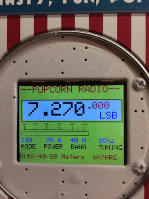
Popcorn Radio
by Jim Purvis WA7HRG
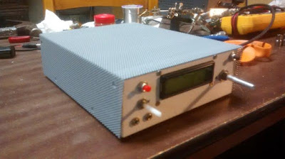
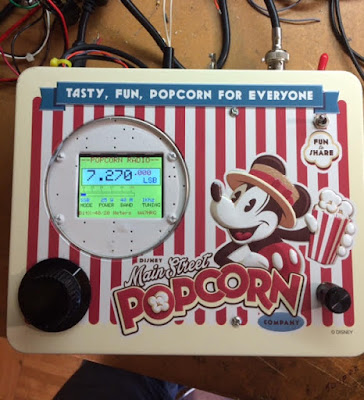
While celebrating Christmas and a Birthday at Disneyland in Dec., my wife and I enjoyed a box of popcorn during one of the many parades. It was too nice a box to toss in the trash so I brought it home. It kicked around the QTH a few weeks until I caught the BitX40 v.3 fever. Wow, just enough room for the BitX and a few hacks, and the project was on. And a very neat way to remember our good time at Disneyland.
I decided on several hacks and mods and made a list. In the end I settled for less. Hihi
1.Switchable 5 or 20 watts out.
2.Single power supply. 24 volt PA with a 13 volt regulator for the rest of the radio.
3.Dual band. 40 and 20 meters.
4.SSB and digital mode operation. Built in audio interface and sound card.
5.A tune function for antenna adjustments.
6.On screen S-Meter.
7.2.2” color TFT display. Because I can display more information and it’s just cool. The Radino it came with was set aside for another project.
I had a 24V 5amp laptop power supply as the base supply. I used two 7812 regulators in parallel and an aluminum plate heatsink and raised the common a little above ground for a 13 volt output. I could then switch that between 24V for the PA. Regulators get a bit warm when using them in the 5 watt position so most operation will be at 20 watts.
Dual band operation was soon abandoned simply do to space limitations in the box. I had no room for additional BPF and LPF.
The audio interface not only provides ground isolation and level control between the PC and the radio it also provides a VOX operation for digital modes. The digi software can provide the PSK (or other modes) audio on the left audio channel and a continuous tone on the right. I use this for the VOX operation. A ‘thumb drive’ size USB sound card provides the connection to the PC with just one cable.
Antenna tune function was provided by a version of Pete’s LBS method and I just used a small relay and a push button to activate PTT and to unbalance the balanced modulator.
The S-Meter proved problematic for me. I might not have had it if not for help and advice from Pete. It may not be accurate but provides a good relative signal strength indication. And looks very cool!
The DDS is a quagmire of several different sketches and some of my own coding. This was my first adventure into actually coding the sketch from (almost) scratch. I am sure I am very close to the maximum times you can program an Arduino as my “Guess and Test” method of coding became very arduous. All switching of mode, power and other functions are done at DC allowing me to use that as inputs on the NANO to change DDS function and displays.
All and all I am very pleased with the way it turned out. Not sure what I’ll do about losing 20 meters. Hmmm guess I’ll just have to build another radio. J
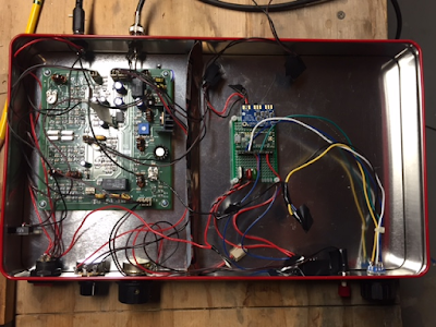
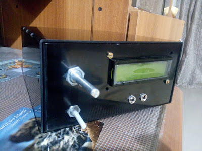
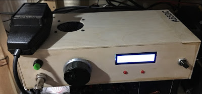
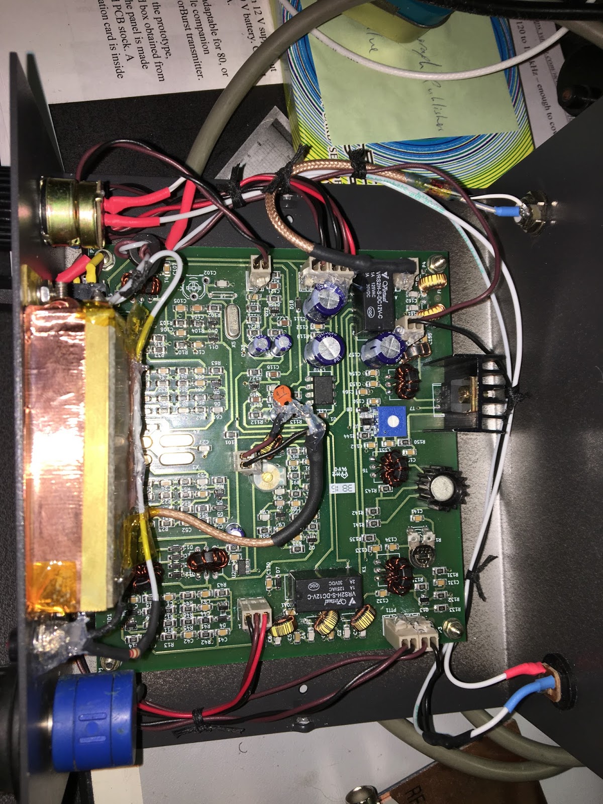
Front cover. Upper Right corner is the Digi/SSB switch. Tuning and vol are at the bottom. All controls and switches were located, sometimes in odd places, to retain the graphics of the box.
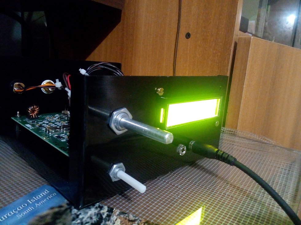
In the lid. Upper left corner is the digi/SSB switch and across the top is the audio interface ckts. TFT is in the middle Right. Below that is the 3.3v level shifter and encoder. On the heat sink are two 7812 regulators in parallel. I raised the common a little above ground for 13v out. Far left is the vol control and S-Meter amp and det ckt.
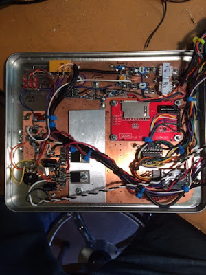
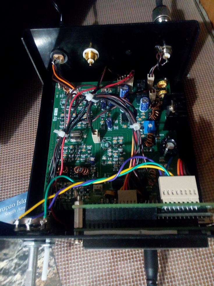
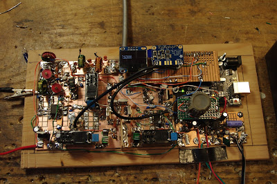
The main chassis. Across the back left to right are power input, spk jack, mic/PTT jack, ant connector, and 5/20 watt switch. Far right is the PA heat sink. A 1x.5×4″ aluminum bar. It’s what I had… Lower right corner is the tune push button and if you look close in the upper left corner of the main board is a mini relay glued to the board near the bal modulator. That unbalances the modulator and provides a carrier for antenna tuning. Upper left of the box below the power connector is the USB Sound Card for the PC interface. And a couple extra input wires I ended up not using. Below that is the standard Nano and si5351.
Last but not least is the 2.2″ TFT. All functions power, mode, etc., are DC switched. I also use that as inputs to the Nano for display changes. I sense the 12 v relay voltages and through a voltage divider to input pins.
It has been a fun project and I can continue to play with it, but I think its time to button it up and use it a little.
It’s back to my General Coverage Rec that I started but never finished.
A year or so ago Pete and I encouraged Kiran VU2XE to try the BITX. He followed through, on our suggestion and went a step further, using CAD to design a box for the BITX.I will try to post a link to Kiran’s CAD files on the BITXHACKS blog. Kiran writes: Hi Bill and Pete,
It is almost year since you seeded idea about the BITX. I am still a listener of your podcast.
After finishing my RF amplifier project late last year, I was thinking of few projects and BITX was on the top of the list. I ordered and received a very beautiful BITX40 kit with Arduino, I got it recently. I also designed a simple case for it using CAD software. It can be used by anyone — just go to your local laser/CNC shop to get it cut in Aluminum. I just thought of sharing the excitement with you. This rig and it sounds awesomely good 🙂
Attached are some snaps and design files (I am no expert in CAD etc. it is my first attempt to learn and build)
The work of Ken G4IIB has been on this blog before — he helped many of us make use of the amazing RTL-SDR Dongle SDR receivers. He has recently turned his attention to the BITX40 Module and offers some great ideas for testing and for modification. Ken’s description of the smoothness of his audio adds a very evocative term to the SolderSmoke Enhanced SSB lexicon.
Hi Bill, Pete
Many thanks for your respective responses to my plea for help in setting up SI5351 derived BFO to my BITX40 board. You were both on the money.
Pete suggested that I had too much gain in my HB amplifier from the SI5351 output to the modulator and indeed that proved to be true. Once sorted I also noted that I was getting extra hiss on switching to one of the sidebands as you pointed out Bill this proved to be due to incorrect placement of that particular BFO frequency.
These BITX40 boards that Ash Farhan has developed and released to the world wide community of Radio Amateurs are worth every penny. Because they are so hackable (not just the circuitry but now the Raduino code also) it means that you can tailor it to your specific specification and in the process you are likely to learn new stuff and make new friends. I describe my BITX40 incarnation and experiences below:
Upon first firing up the BITX I was getting quite a lot of mains hum from my PSU’s (I thought that at least one of these PSU’s was a quality item) but obviously not up to the job. I constructed a simple one transistor capacitor multiplier (this converted a humble 1000uF cap into a 1F cap) and the noise magically disappeared. By coincidence I note that Bill discussed this technique in a recent pod cast. Another advantage of this technique was that I got a 2V drop across the transistor so by running this on 13.8V I get 12V out so I run the PA section on un-smoothed 13.8V (this gives me 12 watts of RF out) and run the receiver section on the smoothed 12V output from the multiplier, happy days.
My thoughts were to turn my BITX into a multi band (several bands rather than all bands) rig and I figured that using high side mixing (running the VFO at 19Mhz (12Mhz + 7 Mhz) rather than the existing low side mixing (12Mhz – 7Mhz=5Mhz VFO)) would be a better option. For example running it on 17M would mean using high side VFO anyway. I also wanted the ability to be able to switch sidebands especially on the lower frequencies so that I could use the rig for Digital modes in my case this was to be achieved by coding the Arduino to run a BFO on one of the SI5351’s clk ports.
I bought my BITX prior to the release of the Raduino so I had already commenced (with the aid of a new found radio friend and RF mentor) coding an Arduino VFO/BFO using a UNO and SI5351. Like I said at the beginning once you let folk know that you are starting on a new and interesting project you start to engage the more practical members of the ham community and they just want to get involved and help. Yet another good reason to buy a BITX . We used code originally developed by Jason Mildrum NT7S and Przemek Sadowski SQ9NJE and tailored it to suit the BITX40 and our requirements. This include high side VFO with frequency step adjustment and a BFO with long push BFO changeover. This meant that my BITX front panel should stay very minimalistic 2 knobs. Getting the VFO to work was simple as the DDS socket was used and to better accommodate the high side VFO I modified the board by tombstoning caps C91 & C92.
Getting the BFO to work proved to be more problematic I was troubled with hiss and other noise. Words of wisdom from Pete Juliano when asked if I was doing something wrong were: ” No –it is just that we tend to think our projects are like Lego type building blocks where everything mates and snaps together. Sometimes more is required”. True Pete and that gives us the opportunity to learn new stuff!
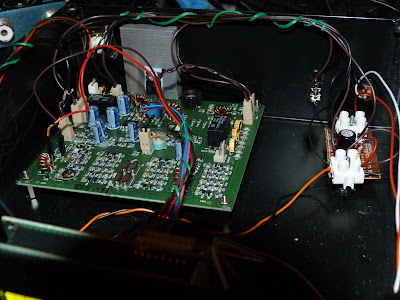
To cut a long story short I found that the best place to connect the BFO was on the modulation transformer T4 thus bypassing the BITX BFO stage altogether. I was also getting hash noise believed to be emanating from the Uno. At this stage my after market Raduino arrived from India. I fired this up and noticed that I was not getting any hash noise from it. This pointed us to a coding problem and the LCD refresh was altered on our code and the problem disappeared. Below a picture of the module showing the BFO connections to T4 and the large heat-sink with the IRF510 insulated from it. Also shown is the capacitor multiplier and a glimpse of the Raduino in the foreground. Not the most elegant box but this is likely to change pending further refinements. It’s still work in progress and this box gives me plenty of room.
The Raduino is a fantastic piece of kit for the money extremely neat and well thought out. The coding is comprehensive and innovative and works well. However, from an aesthetic and ergonomic point of view there were a few things that I personally did not like in terms of how it operates and performs. I could not get away with the potentiometer tuning, you can tune 50Khz of the band and then when you near the pot edge it increments/decrements and you can re-tune. I found this clunky to use and in addition the Raduino would hunt causing the last digit to increment then decrement causing an annoying warble on audio. In my opinion a Rotary Encoder would be better solution. On the plus side, although not mentioned on the Hfsigs web site the Raduino code does come with other functions such as changing sidebands by temporary high siding the mixer, a RIT, VFO B and CW tone. If you download and read the Raduino code from Github you will see this extra functionality which I believe you can make use of via extra switches (not supplied). The current Raduino code does not have any external BFO options as said it relies on the crystal BFO and temporally high siding the VFO to change from LSB to USB on 7Mhz.
The Raduino module itself is just too good and neat not to use. As I did not have the where for all to fully understand and amend Ash’s code I decided to use the Raduino but to load it with the code that we have developed for he Uno and Addafruit SI5351 board. This would give me near conventional tuning via a rotary encoder, adjustable step sizes via quick push of the encoder switch and USB/ LSB switching via long push of the encoder switch by virtue of the SI5351 generating the BFO frequency. I have retained a copy of Ash’s Raduino code just in case I wish to revert to it. I put a new header on the Raduino P3 connector so that I could connect a rotary encoder and use the 2nd clock output and then changed our code to run on a Nano. I had to add a correction factor in the code to cater for calibration differences in the SI5351’s (in my case 1.21Khz).
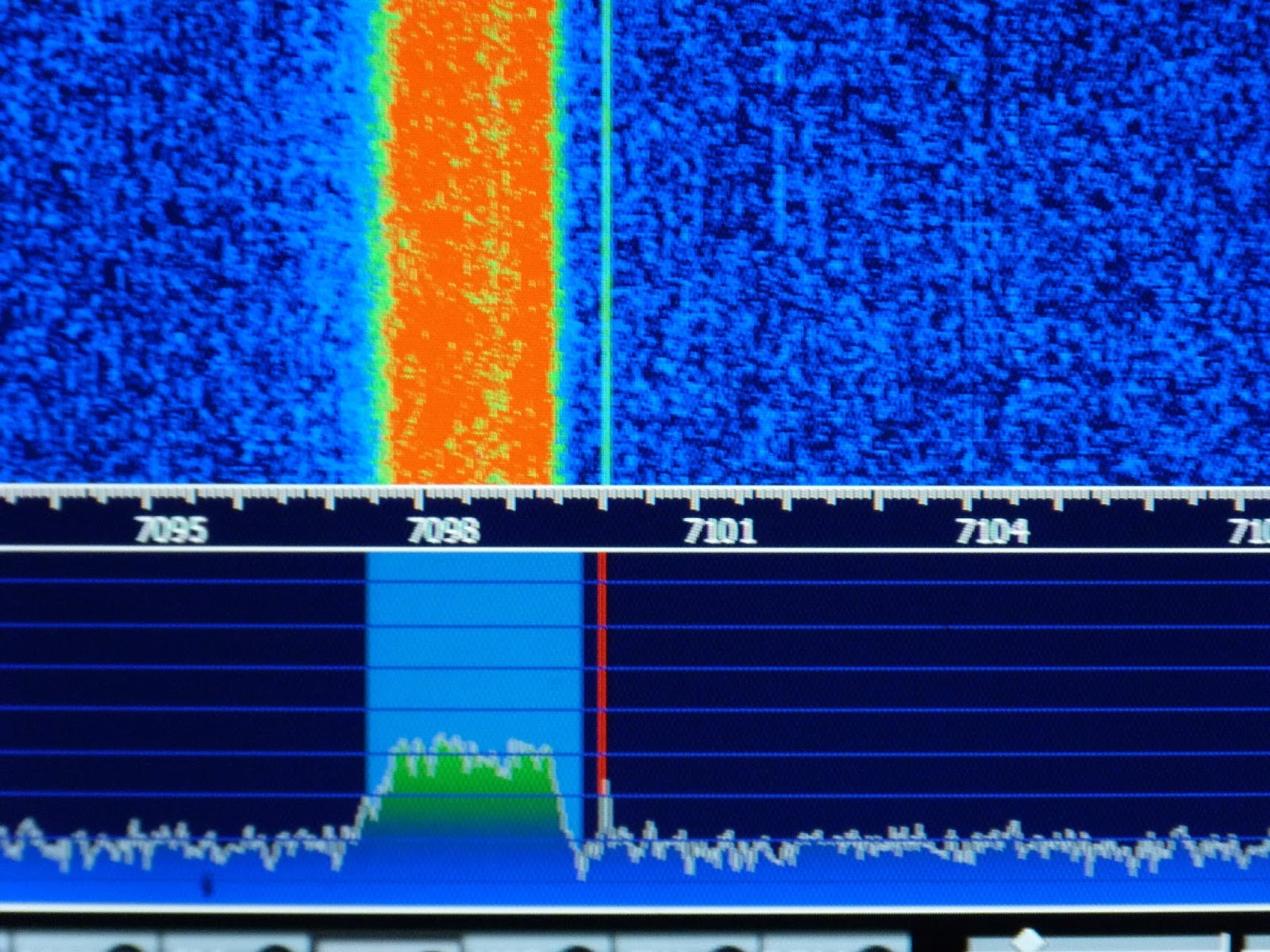
As previously indicated I had a little trouble arriving at the correct BFO frequencies I found that 119940 and 119970 gave me LSB and USB respectively for my high side VFO (19Mhz) if you use low side VFO (5Mhz) then these would be reversed. We further refined these frequencies by injecting white noise into the mic amp and looked at each transmitted sideband on my RTL-SDR dongle via HDSDR (a useful piece of test equipment). By adjusting the carrier trimmer to show the carrier in the extended HDSDR spectrum display we could see how much to move the BFO frequency to best occupy the crystal filter pass band, see image below. This frequency adjustment being achieved by a coding change. The frequencies I consolidated on to cater for my particular crystal filter are 119941 LSB and 119969 USB. We then nulled the carrier back out. My audio is now as smooth as a maiden’s inner thigh, trust me the image will follow!
So now I can get on and build an AGC and think about some sort of S meter. As for putting the BITX on other bands, whilst I now have a VFO capable of going anywhere, I would need to address band pass and low pass filter and switching arrangements. I may still experiment with this but, as pointed out by Ash in a recent pod-cast, the BITX single superhet design is not best suited to multi band operation but can be quite easily changed to operate on another single band. He also indicated that he was developing a dual superhet with consideration for multi band operation. Once released this might be a better option for multi-band use.
In the mean time folk should just get a BITX40, hack it to bits and share with us their customised versions.
Last weekend Homebrew Hero Peter Parker VK3YE hosted another of his amazing twice-yearly QRP events. It was at a park near the iconic Chelsea Pier in Melbourne. Peter Marks VK2TPM sent a very nice write-up with pictures: http://blog.marxy.org/2017/02/qrp-by-bay.html And a nice audio report: http://s3.marxy.org.s3.amazonaws.com/audio/QRP_By_the_Bay_2017.wav Peter Marks reports that most of the on-the-air activity was on the 120 foot ham band (40 meters for you modernists).Many BITX40’s were on display.
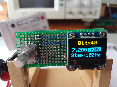
Hugh ZL1UEM has come up with a very creative way to take maximum advantage of the small size of the Si5351 board, the Arduino, and the OLED display. He even has the rotary encoder in there. Look carefully — he uses both sides of the board. Very nice. Thanks Hugh!
Hi Bill,
First let me say that I have been an avid follower of the SS blog and podcasts since the days of your podcasts involving Mike KL7R.
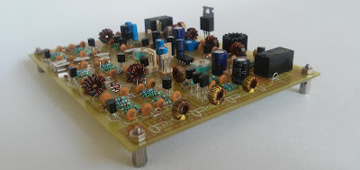
Like many others I was tempted to purchase the $49 surface mount module from HF Signals. As a keen home brewer I felt guilty about employing a prebuilt board but excused my decision on the grounds that I would build a DDS and other accessories myself.
In addition to follow the SS blog I also check Pete’s blog regularly and was excited by his OLED VFO for the Bitx40.
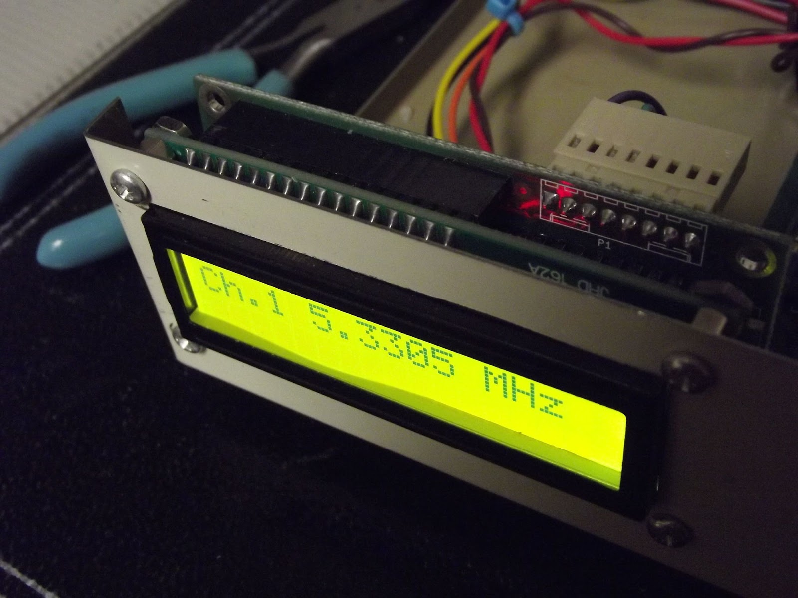
I constructed it on a small double sided matrix board with plated through holes. A bit of noodling led to the layout shown in the photos. There is only one board with components mounted on both sides. The board came to life on the first power up but the text spilled off the bottom of the display.
I assumed that the sketch that I had downloaded from Pete’s blog was for a different OLED module. I knew that he had also used a yellow/blue OLED, the same as mine, previously so emailed him requesting a sketch for this OLED.
I was taken aback when he informed me that the sketch I had was the same for both the dual colour OLED and the black and white one too. Pete suggested that I swot up on the use of OLEDs generally and that perhaps I should first experiment with the text size to begin with. He also offered some advice about the mapping of the screen.
I soon discovered that the text size was not the cause of my grief and that I needed to look elsewhere.
I first tried running the ssd1306_128x64_I2c sketch from the sample sketch folder and was rewarded with the message “Height incorrect, please fix Adafruit _SSD1306.h”. A search of the Internet revealed that I needed to edit the .h file and find “#define SSD1306_128_64” which was commented out and uncomment it and make sure that the other two options, _32 and _16, were commented out.
My next problem was how to edit the specified .h file. I tried notepad but the text all ran together. Another internet search revealed that Notepad++ was a suitable choice and it did indeed cut the mustard.
A reload of the sketch completely restored the display to full functionality.
All this may be obvious to many but it was all new to me and if I had not been prompted by Pete l would not have had learnt so much and would not have had the same sense of achievement when it all came together.
Many thanks to you and Pete for providing a focus for my hobby.
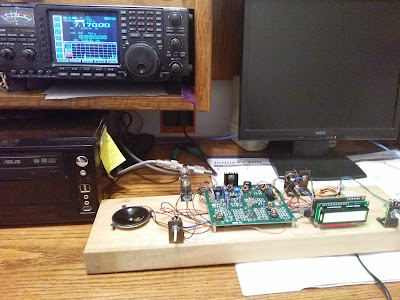
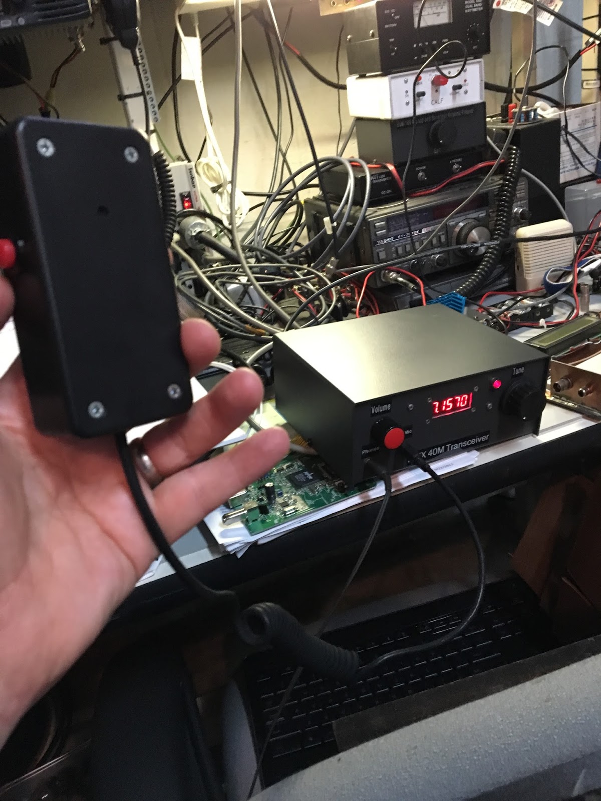
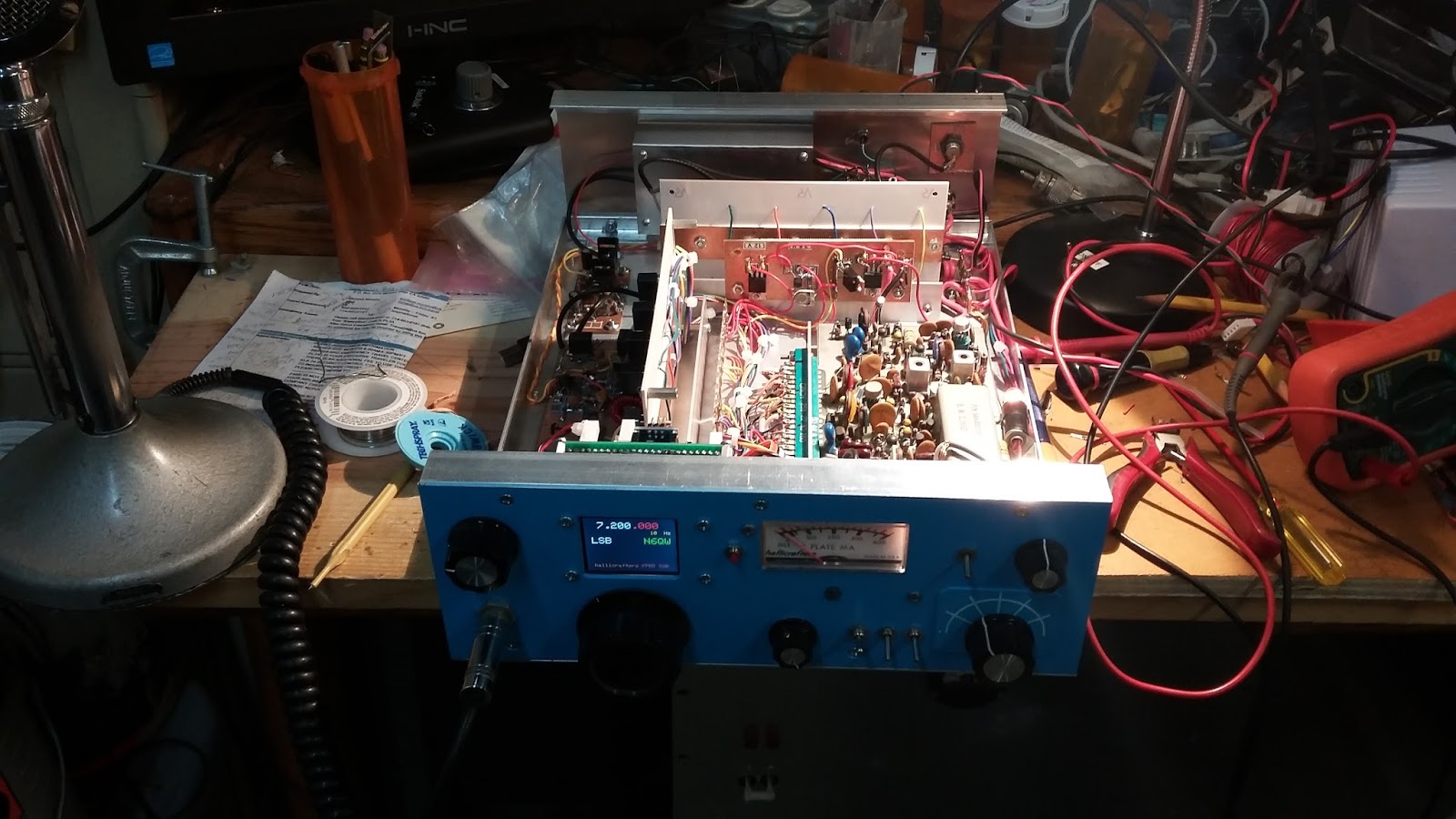
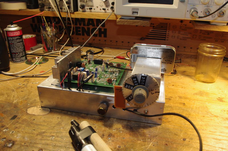
The purpose of the BITX40 project was to encourage modification, experimentation, and more frequent melting of solder. I think these pictures from W8LM serve as yet another reminder that this goal is being achieved. The contrast with the big appliance rig in the background is, in so many ways, striking. You’d be understandably reluctant to take a soldering iron to the commercial rig, but the BITX seems to be crying out for hot iron and solder smoke.
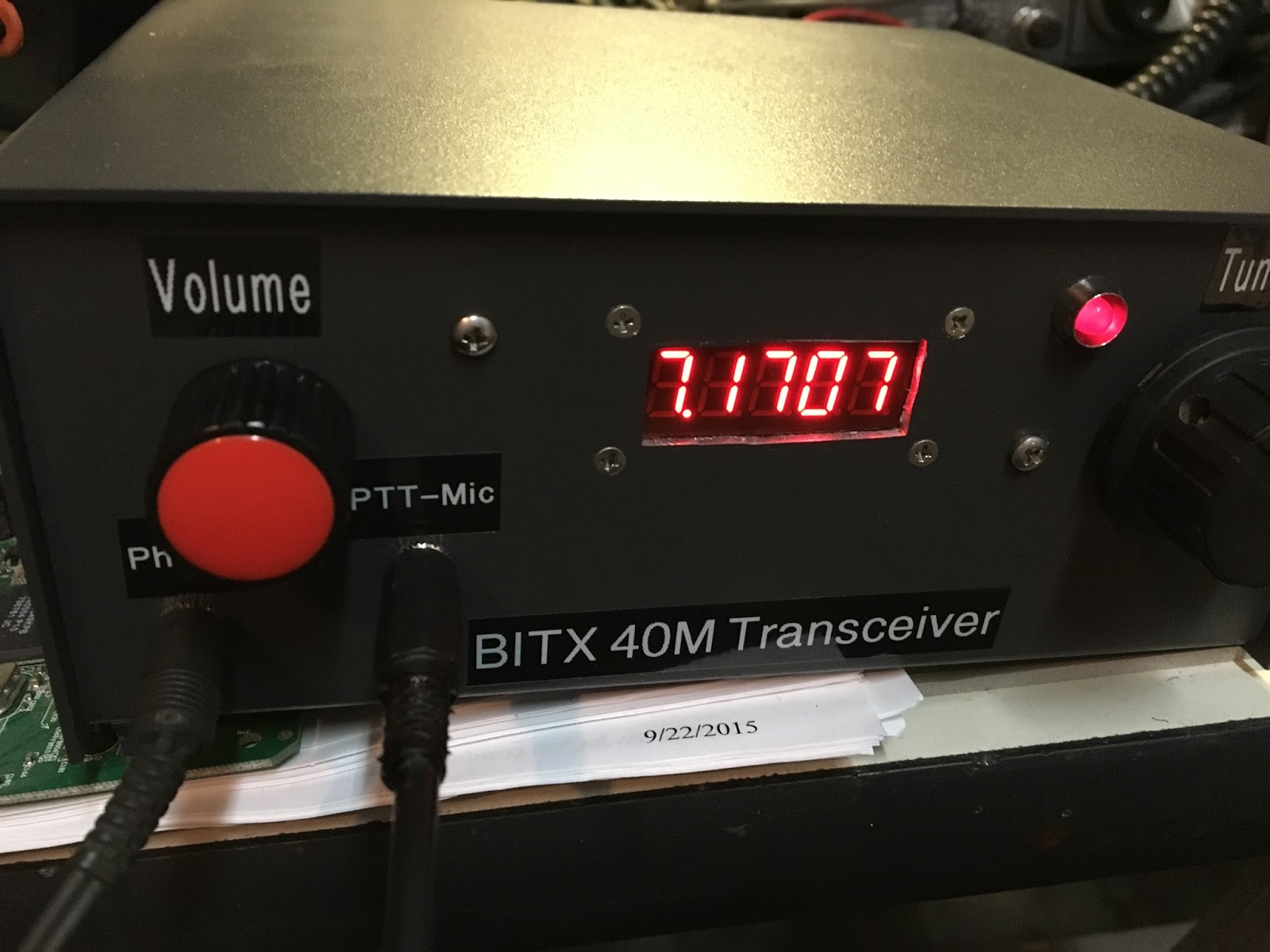
W8LM wrote (on the BITX20 group): Guys- Here are pix’s of my BITX40 fired up today in Receive for testing. #1 I have the tuning clicks- so I will be debugging that. #2 shown in the pictures is my test of calibration which was not necessary. I used a T and put my ICOM 756proII and the BITX40 on the same antenna (a Windom flat top at 33Ft) The display of both read 7.1700 pretty much the center of the band and I was copying 4’s,8’s and 2’s at 23:30zulu) By moving volume controls up and down I could listen to both rigs same frequency, audio comparison acceptable. An AGC circuit is in order. The mylar-plastic cone of the surplus speaker lacks fidelity. Unfortunately the 16×2 display did photograph well. It’s a start– de W8LM
Martin A65DC sent us this wonderful report on his efforts in the UAE. His e-mail nicely conveys his enthusiasm. I was especially pleased to see that wooden enclosures are catching on (another fellow on the BITX20 group is using a cigar humidor). Thanks Martin! Please keep us posted on your UAE homebrew adventures.
Hi Bill and Pete,
My name is Martin, and I am listening to every episode, sometimes more than once, thank you for an excellent show boys. I am a ham in the United Arab Emirates and operate radio as A65DC.
I just wanted to share my “JOY OF OSCILLATION” moment with you, I had the moment two days or so ago.. fantastic!
Well it is not super tidy, but as a proof of concept is totally acceptable. red and green goes to the variable cap (above).
Next to the Mighty Mite (above) is my bitX40, what a fantastic board!! I have big plans for this radio. But for now it will stay in its wooden box and keeps me company.
This (above) is another kit build, 20m SSB kit from EA3GCY Javier. ILER20, please have a look, this is where you should start if you are into kit building!! the instructions are fantastic.
I added some Arduino magic to it with a SI5351, and then I was sitting and looking at my big UNO board, hmmm USB port, why not further develop the code and use the port as CAT control.
I can now connect this rig to e.g. N1MM and control it, read and write frequency (in current version) I am simulating the protocol of a TS590, but that turned out to be a bad choice, I should have gone for a simpler radio, like a 140 or something, the 590 has loads of CAT commands that my code needs to answer… this radio is my QRO 20m as rig it sports the 20w amplifier kit from K5BCQ and will put out a whooping 22w! Several contacts from A6 into Europe and some over to Indonesia.. fun stuff, two kits from different vendors together with some own building and coding.. I love it.
On the workbench now is an Arduino CW keyed based on K3NG, the Arduino code is very well written and it has loads of functionality, most of what I will never use.. but as a keyer it is superb.
This is my keyed circuit, super simple stuff, it is here connected to the Mighty Mite as a test, works 100% I am now researching a good circuit for a CW transmitter/transceiver for 40m that will be in the 5 to 10w range to use my new keyer with.
Report from Pete on BITX 40 Session with California radio club.
Update on the BITX40 Module Revolution — Check out the BITXHACKS page. Send in contributions. — BITX20 mailing list very active. — Raduino! — Interview with Farhan with W5KUB — Eliminating the commercial gear. — BITX 40s on the beach in Australia. FB
Bench Reports:
Pete: — Color Displays! — KWM-4 — OLED MADNESS!
Bill: — Fixing up the old HT-37 HT37 to HT37 QSO with W1ZB — Dabbling in VHF with Ramsey Aircraft band receiver. NOT FUN. — Going all IC with Si5351 OLED NE602 rig. — BANDSWEEP — OLED Noise and the Active Decoupling solution.
Using LTSPICE as a diagnostic or understanding tool.
Of Waterfalls, Homebrew Rigs and Casual Critics on 40 meters. Words of Wisdom from W8JI.
LEXICON: HAYWIRE TOMBSTONE BIKESHEDDING from Todd K7TFC
Some great recent interviews by Eric 4Z1UG: Ian G3ROO Origins of ROO Regen at age 8 Hans Summers G0UPL Balloons! NO COMMECIAL GEAR David White WN5Y ELECTROLUMINESCENT RECEIVER EXPLAINED Rob Sherwood NC0B
MAILBAG:
Chris KD4PBJ’s BITX 40 with improved stability Jerry W0PWE built a DIGITIA! Very nice. Worked Keith N6ORS and heard me! TRGHS Mike AB1YK’s Al Fresco Scratch built BITX. But give that LC VFO another chance Mike! Steve N8NM 30 meter rig with salvaged CB LC VFO. FB Keith N6ORS Franken SDR rig with parts from the 1980s. FB SKN Bandscan from Mike WA6ARA I worked W1PID Jim! What is Mikele up to? Rocking Johannesburg and Kirghizstan via local repeaters:
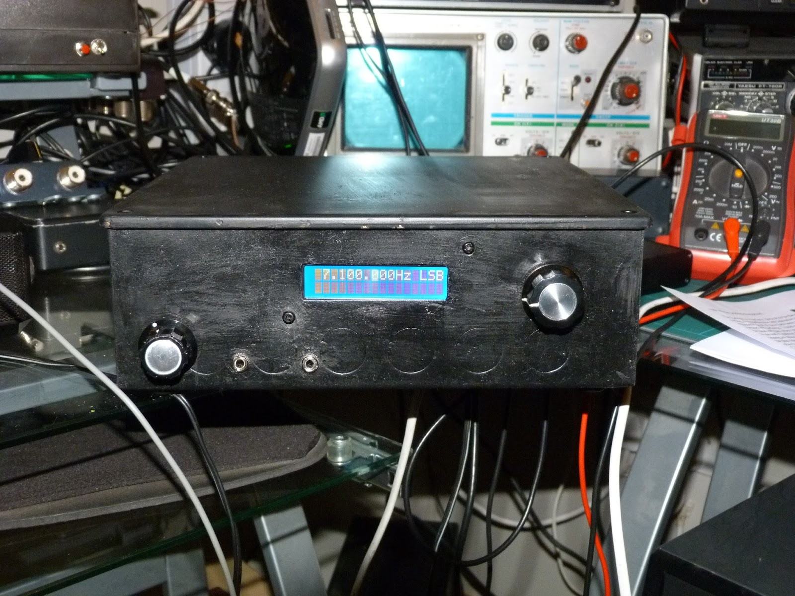
I have to admit something. It’s a learning experience. A year or two ago I bought the Bitx boards from Sunil in India and while they are on the To Do list, haven’t been built up yet. I have close to 20 projects on my to do list, so when Farhan’s prebuilt SMT version became available I decided to get one. I had gone over to TenTec before they shut down and bought a few of their two piece enclosures since I like how attractive they are and also inexpensive. The Bitx went into the enclosure quickly and I measured a little over 10 W out with my scope. I fed a -125 dBm signal in using my HP8640 generator and could easily hear the tone. So a really sensitive receiver. Nice and quiet too! I got a SMT digital dial from QRP Guys and got it in the case. Now I heard a high pitched whine in the background. Nuts! So I posted to the Bitx yahoo group asking for help in reducing the noise. I built a R/L/C filter network, added ferrites, built a copper clad and brass enclosure for the display. Nada. Noise still there. Adding adhesive copper tape didn’t help either. This was driving me mad. For some reason, and I don’t know why, one evening I decided to try a gel cell. Success!!! No noise whatsoever. Here’s what happened…. When I first built the radio in early December I tested it on my operating bench. On that bench is a older Power Designs 0-60V 0-5A linear bench supply. After adding the display I did integration on my soldering lab bench and for that I grabbed my HP E3610 supply which it turns out is heavy but switching, not linear. The noise was coming from the supply!! If I hadn’t tried the gel cell it may have taken me a long time to figure this out. Saturday of last week was my first contact with it. I worked two Canadian stations with it, and both came back to me the first time after I answered their CQ’s. I did have one issue and that’s the well documented drift. During the QSO I watched the display drift upwards as I held the PTT button down. I replaced the 100 pF and 47 pF chip caps in the VFO with disc ceramic parts from Mouser and now it doesn’t drift. While doing the work in the VFO section I also tweaked the trimmer cap a bit to bring the bottom range up to the start of the phone band, as before the bottom end was below 7 MHz and I figured that didn’t do me much good for a SSB rig to waste a lot of its tuning range on the CW segment. Here are a few pictures. Mic is home brew too, having made it for my MMR-40 rig.
Hope all is going well for you and looking forward to the next Solder Smoke.
There is so much great homebrewing going on down-under. It makes me jealous. And so much of it is for phone. FB. I really like VK3YE’s sand graphic proclaiming to the world (or at least to the beach!) that a BITX40 to BITX40 contact had been made.
Looks like both rigs were using VK3YE’s ceramic resonator mod for the VFO.
W5KUB has a really good interview with Farhan. There are several spots where the Skype connection gets quite choppy, but hang in there — it gets better. Farhan provides a lot of good info on the history of the BITX rigs, his design philosophy, and the importance of the EMRFD book. He also talks about how the BITX 40 Module is produced. And he talks a bit about possible future rigs. Great stuff. I was very pleased to hear that Farhan is trying to eliminate the need for his FT-817 (he currently needs it for its general coverage receiver) so that he can have a completely homebrew hamshack. FB!
Some fellow jumped into the BITX20 yahoo group this morning, casting aspersions on our friend Farhan. The fellow alleged that a lot of money was being made on the BITX 40. He seemed deeply unhappy about the shipping materials and found fault with the documentation that came with the boards. Farhan came back with a very gentlemanly and detailed response. He was a lot more patient and temperate than I would have been. And when I think about how Pete would have responded, well, it would likely have involved — at the very least — a lot of colorful words from Southern Italy. Anyway, below (unedited) is Farhan’s response. I think it provides a lot of very interesting background info on our beloved BITX 40 Module and on the place that these boards come from.
thanks for writing in, I couldn’t get your handle from the mail, so do excuse me for improper address! I think you have raised from valid points. I think it is important that everybody understands what tried to do, what we did and where we are now.
this is going to be a long and full of personal details that i didn’t consider to be of any interest to the group and hence it was kept out. but i guess, i need to let a few cats out of the bag.
i am retired, early. i had a modestly successful run in a few businesses but i had promised myself to retire from active work, which i did around five years ago. i no longer run any for-profit businesses. most of my investment goes into ‘stuff that matters’. i founded a libera cultural space in hyderabad, i am a partner in a strategic venture fund that promotes technologies that are important rather than profitable. neither ehsan nor i are any longer running anything full time. i do mentor some startups now and then but never as an investor.
i would be only too glad if someone else takes over the entire hfsigs approach. the design has been out in the open for more than a decade. apparently, it doesn’t make economic sense to make them at $45 dollars a pop. so, there is nothing preventing others ‘creaming the market’ if they want to. surely, the turnover is modest but it is not profitable.
it is fallacy that India is cheap. In Hyderabad, a modest apartment will cost you over 250K USD. An independent house in a reasonable area goes for a million USD. A gallon of gas will costs you more than 5 dollars. smart people are hired by facebook, google and microsoft. they have a big a presence here as in the valley and seattle. there is no healthcare, all education is privatized and has to be paid. there is no social welfare. the multinationals they pay top dollar and that drives the living index up, not down. a quick indicator is that only 7% of the population of Hyderabad moves in cars and taxis and they account for 85% of the traffic congestion. our purpose is not provide the women who work low wages, but respectable wages. but i am getting ahead of myself…
Two years ago, our local club conducted India’s annual hamfest. As a part of the delegates kit, Ehsan and I decided to put free BITX PCBs in the kit. These were done without any commercial interest. At this time, the hamfest was still short of money, so we decided to buy the back page ad of the souvenier to help them with the money. I had to put in something in as text, I decided to put a message in the name of HF signals (which was the name of the wiki that is still up at www.hfsignals.org). We distributed a 1000 PCBs for free. Only a few turned up on Air. It was time to do something.
Later, in 2015, I decided to conduct a workshop to help those interested in assembling the PCBs. asked them to get the components off the local shops and we settled down to do it. i discovered that a seemingly simply job of scrapping the enamel off a copper wire would take them hours and often they’d end up doing it the wrong way. the PCBs were badly designed too. we aborted the attempt. i had learnt something : homebrewing cant be taught in a day. first fail.
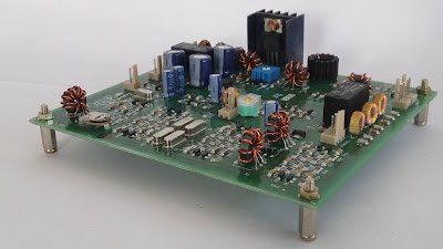
i also figured that it might be easier to begin with something that is already working and then start modifying it. something that happens in open source all the time. so,i sat down and designed a new single side pcb .. with through-holes, on Express Pcb. we turned up 100 boards, found a group of five young girls who were laid off after the unit where they worked to assemble TVs had closed down. showed them how to assemble the boards. they made quite a few mistakes. the transformer windings got mixed up, resistors got swapped, the transistors were inverted, etc. each board was an adventure. you can probably see some pictures of these boards floating around. they were cheap to produce. the actual component cost of the bitx is ridiculously low. it cost us about 1000 rupees in components, another two hundred for the assembly and testing and a hundred bucks to ship it. we rounded it off to Rs.1500. About 100 of them were sold. it gave me nightmares. each board took an hour or more to fix. i decided not to do it at all. we rolled up the operations after a while. second time, fail.
by now, i had given up on doing anything with bitx boards. but a conversation with convinced me that SMD might be the way to go. we looked around and found a local SMD shop that agreed to do small runs for us. the smd components are much more expensive in india. we decided to keep the more expensive components like crystals, electrolytics in through hole format. i had to learn kicad. the women were now retrained to do the windings, insertion of through hole components and two rounds of testing. the component cost was at Rs.1500, another Rs.200 to the SMD insertion machine, Rs.200 for through hole insertion, testing. add another Rs.100 for packing and Rs.100 for local posting. we were selling these for Rs.2400 inside india and 45 dollars (a few hundred more to cover the additional expense of international postage) outside.
now, we come to the packing and shipping saga. the DHL/Speed Post quoted above Rs.1500 for shipping it internationally. that would be nearly 60% of the board’s sale price. instead, we looked at the ordinary postal service. so, we bought some amazon shipping cartons, assuming that these must be good enough for us as well and shipped some boards to friends around the world. we shipped five of them with the boards in bubble wrap. all fo them arrived in good shape. we rolled with this. WE USED BUBBLE WRAP. When we started actual shipping, we realized that the bubble wrap wouldn’t prevent the carton from collapsing. the coils were getting damaged. we needed some kind of a stiff roof over the board so the box’s sides wouldn’t collapse down. That’s when we started using the foam plate over the board. The foam provides a physical shield for the coils. The foam + the amazon cartons worked for a while. Then, we ran out of cartons.
Diwali is the christmas equivalent in India, the packing materials just disappeared from the market. we looked around and bought some other cardboard gift box. we sent them out as gifts to another set of people, they reported no problems, so we continued with those. after a while, we started getting complains about those boxes as well. then, we started looking around for something else.
we found these plastic boxes to be sturdy. we tossed them around, shipped them to a few volunteers around the globe and finally agreed that these were holding up. so we continued with these boxes. these boxes are costly. they are not ‘cheap’. i am personally averse to using plastic, but we thought that these were the best for the purpose. if anyone has a better idea, do test it out and let us know. we are always glad to accept anything better.
we buy our toroids from w8diz. these are genuine micrometal parts. the pcb is of high quality made to ISO-9000 standards. we import components from mouser. the only thing that we do on the ‘cheap’ is that we use microprocessor grade crystals that we sort out manually.
What’s the current serial numbering up to as of December. Anyone know? It was #465 in early December. 465 units multiplied by $45 USD is about $21,000 USD. That converted to INR has the purchasing power in India of $70,000 USD here in the US. That’s a lot of bread.
we have shipped 1000 boards. we got 45,000 dollars in revenue and we have not yet recovered our expenses. i have provided you with the figures. add them up. as i said above there are far easier ways to follow to make money than bother with these boards. that’s why no one else is doing it. the design is in open source anyway.
What’s my point?
Seems like with that kind of wealth in play:
1.) The product could be double-boxed and well bubble-wrapped so it arrives undamaged after it’s 12,500+ km trip from Hyderabad. Old candy boxes or scraps of waste paper taped together just isn’t doing the job. Broken product means unhappy customers and a bad reputation.
as i said, bubble wrap didn’t work. there will be enough people here to vouch for that. we did try it.
2.) The single schematic that represents the functionality of the product could be up-to-date and error-free.
this is the schematic that was used to produce the PCB. where are the errors?
And for totally optional bonus points: A section by section Theory of Operation write-up that explains exactly how all the sections operate and how to troubleshoot. If a template is needed, look at vintage HP test instrument manuals or Heathkit ham radio transceiver manuals. Hint: Saying that, “It’s all been explained many times before on many forums, Google it.” does not get any points.
surely, it could be done. probably it is already done. bitx happens to be most well documented radio now. it is a community effort. look at http://golddredgervideo.com/kc0wox/ and soldersmoke and arv’s work and the large amount of stuff in the file section of the bitx group and you will realize that more people know, understand and write about bitx than a proprietory manual might contain. if you think it is lacking, go ahead and write some more documentation.
oh, btw, Ehsan is not an Ayn Rand supporter. He is a radically liberal guy who is more at home with the socialists at lamakaan than the suits of the software gang.
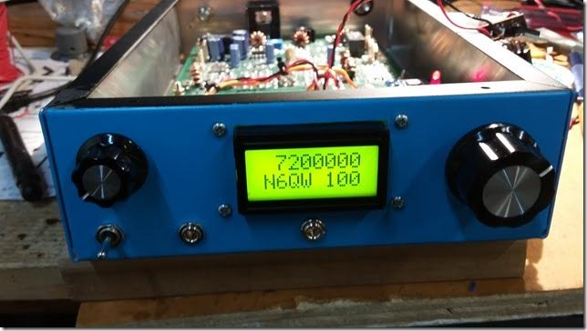
A very nice Christmas present from Farhan in Hyderabad! An Si5351/Arduino Nano VFO for the ALREADY AWESOME BITX 40 Module. I’m really glad Farhan kept the digital stuff on a separate board — it just seems like the right way to do it. Details on http://hfsigs.com
As the proud owner of what has to be one of the world’s UGLIEST BITX 40 Modules. I feel somehow qualified to declare Pete’s version of this rig to be one of the world’s most beautiful. His is resplendent in Juliano Blue — mine has no paint at all. His features glowing numerals — mine has nothing but Dymo stickers and an arrow drawn with a Sharpie marker. Bravo Pete!