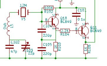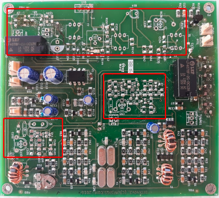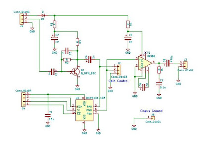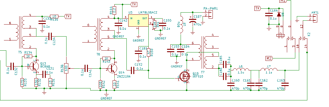
PA shematic from the BITX 40 Module
Click on the diagram for a better view
C.F. Rockey W9SCH (who alerted us in SPRAT 22 to the chicken sacrifice option) spoke of transistors that exhibit “quantum mechanical necromancy.” Rockey explained that when this happens, “The transistor simply turns up its toes and dies. Not even an Atomic Physicist can tell you why!”
This often (very often!) happens with homebrew power amplifiers. So when we find a good one, many of us stick with it, using the same power amp circuit in rig after rig. I have done this with the power amplifier from the BITX40 Module.
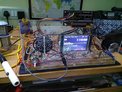
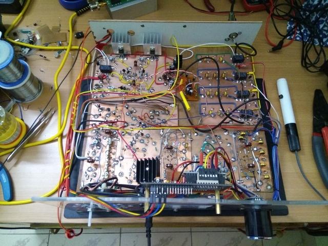
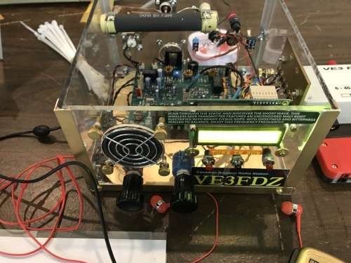
Mythbuster (75 & 20 Meter) version (early)
Click on image for a better view.
https://soldersmoke.blogspot.com/2021/08/mythbuster-video-13-rf-power-amplifier.html

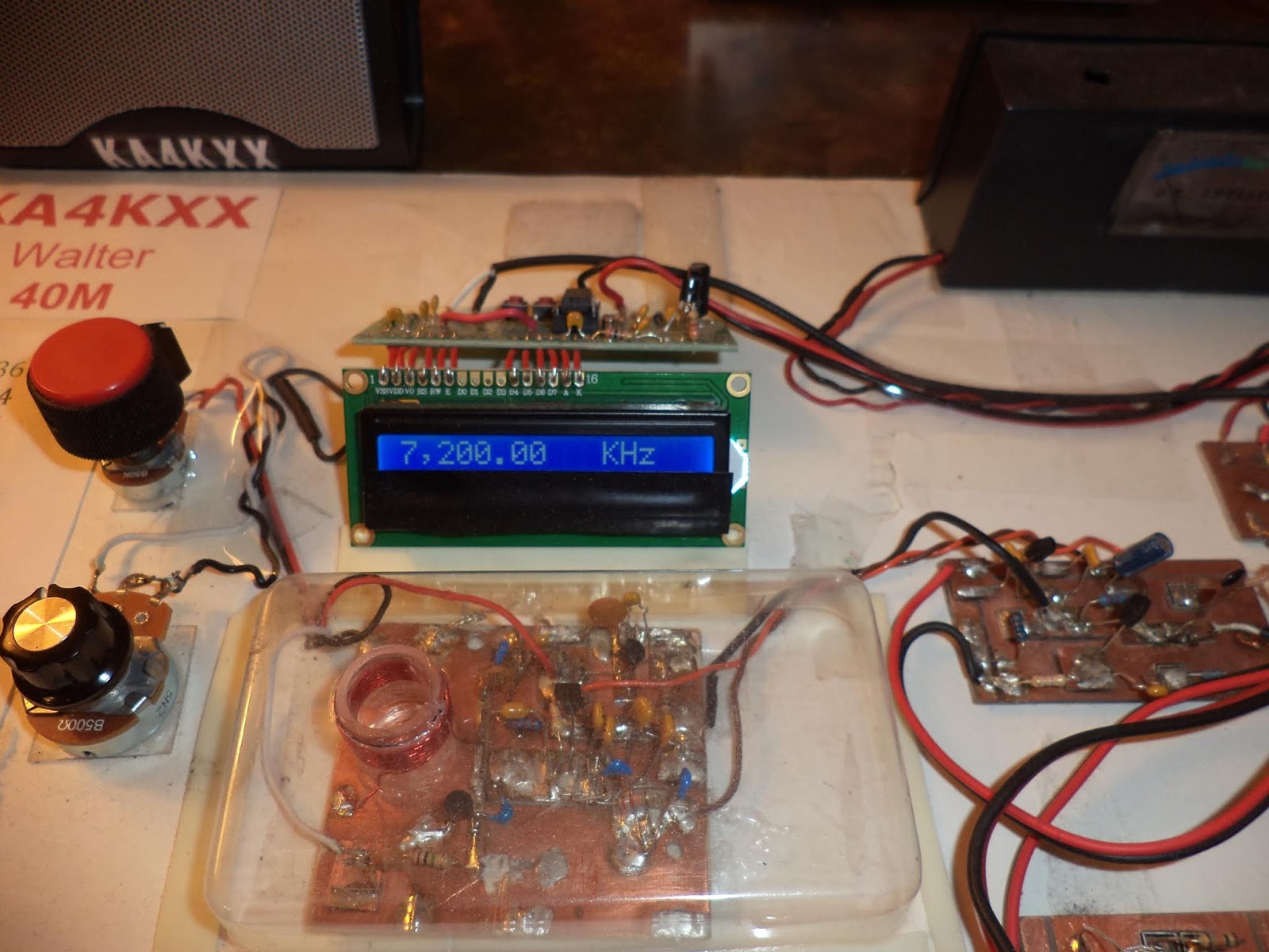
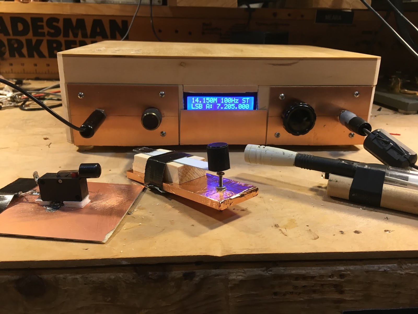
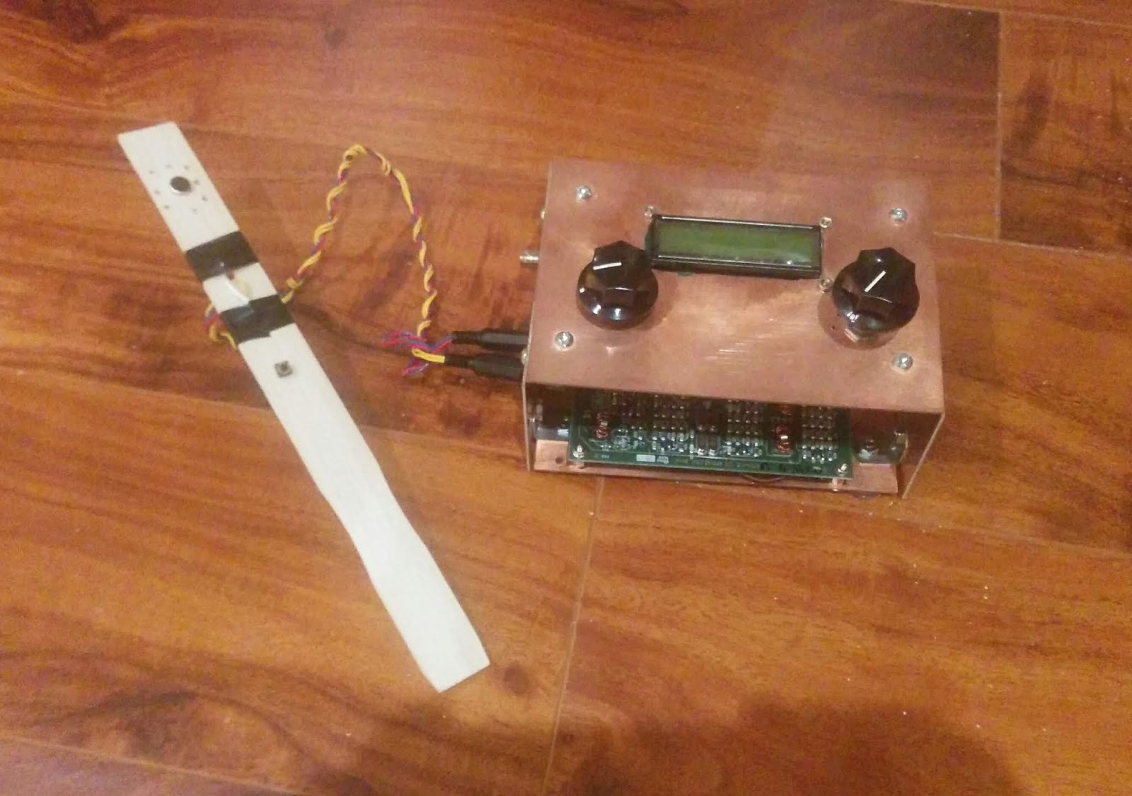
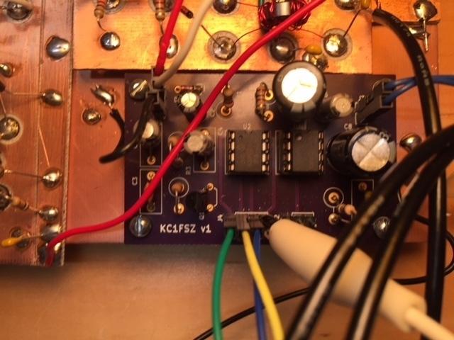
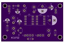
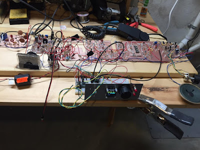
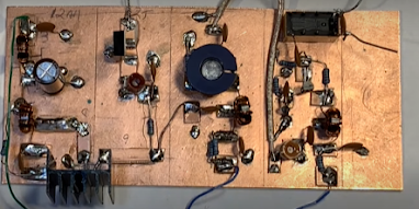
Same amplifier built into Version 2 of the 15-10 Transceiver
Click on image for a better view.
In the build for the 15-10 transceiver you can see some changes. I used an RD06HHF1 instead of an IRF-510. I used an 8.1 volt zener diode instead of the regulator chip. I set the bias at around 5.5 volts DC on the gate of the RD06. I used a smaller, metal can driver transistor (it works fine). I changed the input/output physical configuration between the pre-driver and the driver stages (I think it was kind of goofy the way I had it in the Mythbuster). Finally, you can see how I used a small piece of copper tape (with conductive adhesive) to shield the line going from the driver transformer to the gate of the RD06. The wire was too small to use a bit of shielded coax, but I think the copper tape and the copper clad board beneath it work just as well.
Farhan provided me with some fascinating background on this circuit:
Bill,
I just saw your post on the bitx40 power amp. The credit must go to Wes for this, it is from the Lichen transceiver described in 6.9 of the EMRFD. I merely copied it with some modifications for it to work with junkbox components.
It bears mentioning that at that time I didn’t have a way of generating two tone signal or measuring the IMDR. Those came later when I built my own spectrum analyzer based on Wes and Terry White’s spectrum analyzer. It was sheer luck that I picked this power chain that already had careful gain distribution.
For the output, the original build used and LPF with inductors wound on a ballpen shell and TV baluns cores instead of toroids. Again, it was incredibly lucky that they worked at all.
– f