BITX Build Update #15 — Necessary Mic Amp Mod

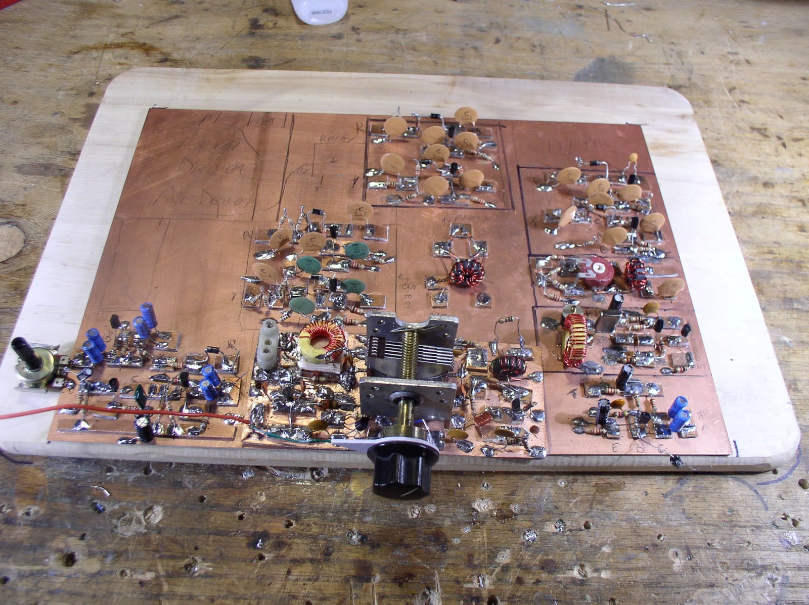
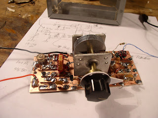
I was having trouble with the mic amp on my new Manhattan Discrete BITX 17. I had it wired as per the schematic, but it just wasn’t working right — I was getting very little DSB out of the balanced nodulator, but everything worked fine if I 1) unbalanced the bal mod or 2) injected audio (from a sig generator) directly into the audio in port of the balancec modulator. Clearly something was wrong in the mic amp circuit. I noticed the collector voltage seemed quite low.

Some quick Googling revealed that others had struggled a bit with this problem also. Nicolae’s note was especially illuminating and useful:
http://users.tpg.com.au/nfieraru/Electronics/BitX20_Mic_Preamp.htm

As Nicolae noted, the 10K value may have worked with lower gain transistors. We must remember that BITX was (very admirably) designed for minimal cost and maximum use of scrounged parts.

I swapped the 10K resistor for a 39K and all is right with the world. The band is not yet open here, but I bravely called a European aeronautical mobile station, hoping that he would be my first QSO on this rig. I think he heard me, but no QSO (yet!).

Our book: “SolderSmoke — Global Adventures in Wireless Electronics” http://soldersmoke.com/book.htm Our coffee mugs, T-Shirts, bumper stickers: http://www.cafepress.com/SolderSmoke Our Book Store: http://astore.amazon.com/contracross-20

BITX Build Update #14 — STABILITY!

Good news on the BITX. I think I have solved the low frequency oscillation problem in the power amplifier. I tried running the PA off a separate power supply — the oscillations disappeared leading me to conclude that the feedback was taking place via the power supply lines. I put a 22 uF cap to ground from the top of the PA’s RF choke. With this cap in place I can dispense with the separate supply kludge. The amp is stable.

This morning I also resolved a different stability problem. I’m using a relay for T/R switching. One set of contacts controls the DC power, the other set was supposed to disconnect the receiver input from the antenna/lowpass filter when on receive. But I had positioned the relay too far from the LP filter and RX input, so I ended up with this long piece of coax that was hanging off the PA output terminal and carrying lots of RF on transmit. Yes, this led to oscillations. I thought about repositioning the relay, but I think part of the problem is that even if optimally positioned, the long unshielded contact levers inside this relay would be radiating a lot of RF and causing stability problems. So instead I put a small reed relay very close to the PA out and RX in connections. It carries the signal to the receiver when in R mode, and disconnects the RX when in T mode, without any long coax lines or unshielded relay levers. It works.

I still have a few things to do:
— I need to build a proper speaker amplifier so that I can dispense with the amplified computer speakers KLUDGE.
— I need to get a 3 pole double throw switch and some crystal sockets so that I can switch crystals from the front panel. Three rocks will cover all of 17 meter phone.
— I have to build a case for this rig. I’m thinking wood, with tin or aluminum sheeting glued to the inside (for shielding).

Our book: “SolderSmoke — Global Adventures in Wireless Electronics” http://soldersmoke.com/book.htm Our coffee mugs, T-Shirts, bumper stickers: http://www.cafepress.com/SolderSmoke Our Book Store: http://astore.amazon.com/contracross-20

Yikes! Screeching Transistors Throwing off Blue Light!


I found a quote from Doug DeMaw that I wanted to share. This one seems appropriate as I struggle with unwanted oscillation (and as Halloween approaches). From the January 1986 QST:

“Self -oscillation occurs not only in the low-frequency and high-frequency spectrum, but it often takes place at audio frequencies! I have actually heard the transistors “screeching” when strong audio oscillations were taking place in a homebrew transistor power amplifier. On one occasion I could see a bluish glow coming from within the transistors (visible through the ceramic heads of the devices) during a period of instability. Needless to say, the transistors self-destructed.”

I’ve been having some instability problems with my BITX 17 IRF510 final. But I think I have the problem identified. I was getting low frequency oscillations (around 100 KHz). Tonight tried putting the IRF510 on a separate power supply. The oscillations ceased and I am getting a nice clean 3 watts out. So I’ll go back and beef up the decoupling on the power supply lines.

Our book: “SolderSmoke — Global Adventures in Wireless Electronics” http://soldersmoke.com/book.htm Our coffee mugs, T-Shirts, bumper stickers: http://www.cafepress.com/SolderSmoke Our Book Store: http://astore.amazon.com/contracross-20

SolderSmoke Podcast #155 BITX17, TEK465

Podcast # 155 is available for download (or you can listen by clicking on the button above):
http://soldersmoke.com/soldersmoke155.mp3

October 14, 2013 (Delayed Back-to-School edition)

Topics covered:

— BITX Beauty — Building a BITX17

— VFO woes, and the wisdom of Doug DeMaw’s love for crystals

— Why does a 55 year old man NEED clear nail polish varnish?

— How the VFO KILLED the Tek 465

— Trying to fix the Tek 465 (not for the faint of heart)

— New products: Justin Beiber Duct Tape, bifocal safety glasses,
magnetic reading glasses, Ward Silver’s new book

— Backwards British Bike Brakes

— MAILBAG

Our book: “SolderSmoke — Global Adventures in Wireless Electronics” http://soldersmoke.com/book.htm Our coffee mugs, T-Shirts, bumper stickers: http://www.cafepress.com/SolderSmoke Our Book Store: http://astore.amazon.com/contracross-20

BITX BUILD UPDATE #13 — VIDEO TOUR

I hope to get the next podcast out within a week or so. The BITX has been keeping me busy!

Our book: “SolderSmoke — Global Adventures in Wireless Electronics” http://soldersmoke.com/book.htm Our coffee mugs, T-Shirts, bumper stickers: http://www.cafepress.com/SolderSmoke Our Book Store: http://astore.amazon.com/contracross-20

BITX Build Update #11 — Peakin’ and Tweakin’

Oh how I love the sound of a newly built receiver! I’m sitting here listening to G0MJS on 17 meters. Lots of other stations from across the pond coming in very nicely.

Earlier in the week I had some sensitivity problems. I could hear the noise floor, but just barely. And the receiver just seemed to have trouble inhaling. So I started poking around. It seemed that each poke improved things a bit. I had used Farhan’s original schematic (mostly). Later versions put an additional transistor in the IF amp. So I went ahead and added that mod. That helped a bit. Then I noticed that BFO energy was getting into the AF amp. So I put a .1uF cap to ground at the input to the AF preamp. That took care of the RF and did no damage to the AF.

But the rig still seemed a bit hard of hearing. This morning Farhan advised me to take a look at the mixers. I used some junk-box diodes that I didn’t know too much about… I measured the forward resistance and found it to be quite a bit higher than the usual 1N914s. So I switched all 6 mixer diodes. That helped noticeably.

I also checked the input bandpass filter. It seems OK. In the process I learned to use the EMRFD filter programs (thanks Wes) and the ELSIE filter program (also very nice).

Anyway, the rig sounds great now. On to the transmitter.

Farhan advises building the power amplifier on a separate copper clad board. But I have room for it on my main board. Should I live dangerously?

Our book: “SolderSmoke — Global Adventures in Wireless Electronics” http://soldersmoke.com/book.htm Our coffee mugs, T-Shirts, bumper stickers: http://www.cafepress.com/SolderSmoke Our Book Store: http://astore.amazon.com/contracross-20

BITX Build Update #10 — Darling(ton)

Having concluded that I was significantly short on overall receiver gain, I went in yesterday and changed my AF amp from a 40db direct-coupled circuit to a 100db Darlington pair. I immediately noticed a big increase in audio output.

I did a quick receiver alignment using my Arduino/AD9860 sig generator. First I determined the actual bandpass of the crystal filter: 4.998170 MHz — 5.000960 MHz. Using a freq counter, I set the BFO at 5.00126. I immediately started hearing 17 meter SSB signals from the West Coast. That’s always a nice moment: first signals through a new receiver. Kind of like “first light” in a new telescope. Even with the filter ripple, it sounds great.

I think I’m still significantly short of gain. Audio is still faint. I notice that in the BITX17A they have added a second transistor (Q17) in the second RX receive amp. Maybe I should try something similar. Or should I add some gain in the audio chain?

I’m really enjoying this BITX project.

Our book: “SolderSmoke — Global Adventures in Wireless Electronics” http://soldersmoke.com/book.htm Our coffee mugs, T-Shirts, bumper stickers: http://www.cafepress.com/SolderSmoke Our Book Store: http://astore.amazon.com/contracross-20

BITX Build Update #9 — Discretion

With the exception of the PA, all of the stages of my BITX 17 are built. Over the weekend I put in the DC wiring for the receiver and the inter-stage connections (using the Belden coax with the exposed shield and Teflon di-electric). It looks nice.

In my experience, almost all new superhet receivers require a certain amount of debugging and coaxing before they will work. This one is no exception. The VFO and the BFO work fine, and all three RF and IF amp stages are also good. The bandpass filter that I built passes the desired band and tunes up nicely on the right frequency. The product detector was acting weird and wasn’t balancing out properly, but I got that all sorted.

I can put an 18.110 MHz signal at the antenna connection and see the signal go through the bandpass filter (with loss), on to the RF amp stage, to the first mixer where it meets the 23 MHz energy from the VFO. A very messy mixture goes from the mixer to the first IF amp which sends it to the 5 MHz Cohn filter. The filter works, but it has a lot of ripple, so I need to work on the termination impedances. Second IF works fine, then the signal goes to the product detector. AF comes out.

Here’s where the discretion comes in. Instead of the LM386 chip, I built a 40db two transistor direct coupled AF amplifier.

So it all works, but the receiver is quite deaf. I think I just don’t have enough gain in the whole system. I looked at the schematic for the BITX-17 kit. It very helpfully has total (net) gain figures for the RX. I can see that my current configuration comes up short.

Here is what I’m thinking of doing: I might replace the 40db direct-coupled AF amp with a 100 db Darlington pair. I really like the discrete Darlington AF amp that KD1JV has in his “all discrete” transceiver:
http://kd1jv.qrpradio.com/ADC/ADC-40.htm Nice. 3 2N3904’s driving a speaker. I may use that.

Our book: “SolderSmoke — Global Adventures in Wireless Electronics” http://soldersmoke.com/book.htm Our coffee mugs, T-Shirts, bumper stickers: http://www.cafepress.com/SolderSmoke Our Book Store: http://astore.amazon.com/contracross-20

BITX Build Update #8

Big progress on the BITX: All the bidirectional amp stages are done. A bag of 20 5 MHz crystals arrived from Mouser today. I put one in the BFO/Carrier oscillator and it fired right up. I’ll soon be checking frequencies on these crystals, looking for four that are closest in frequency for use in the filter.

While waiting for the mail I built the audio amplifier for the receiver (lower left corner in the picture above). Here I need some advice/encouragement: In an effort to keep this rig “all discrete” I decided to dispense with the LM386, and replace it with an AF amp using individual transistors. I found a circuit in the 1980 ARRL Handbook that I liked. It has two direct coupled transistors, one NPN, the other PNP. I went with a 2N3904 and a 2N3906. The Handbook said it would yield 40 db gain. I figured this was a close enough replacement for the 46 db gain of the LM386.

As usual, I’m not sure of the impedance matching. I built the first AF stage from the BITX schematic (the stage that precedes the LM386). It goes to a 10K pot. The wiper of the pot would normally go into pin 3 of the LM386. I have the wiper going through a 4.7 uF electrolytic into base of the first transistor. The Handbook says the circuit has an input impedance of 1000 ohms. Does my arrangement sound OK?

Output impedance from this Handbook circuit is also 1000 ohms. I tried it with some HI-Z headphones that I have, putting AF in from my Maplin AF sig generator. It sounds OK. Not a LOT of audio available. But OK. I may need one more stage to drive a speaker.

Our book: “SolderSmoke — Global Adventures in Wireless Electronics” http://soldersmoke.com/book.htm Our coffee mugs, T-Shirts, bumper stickers: http://www.cafepress.com/SolderSmoke Our Book Store: http://astore.amazon.com/contracross-20

BITX Build Update # 7

As you can see (above) I’ve made lots of progress on the BITX-17. Going counter-clockwise from the lower right, you can see the mic amp, the BFO/carrier oscillator, the first mixer, the first and second bi-directional amplifiers, the diode ring VXO mixer and the VXO.

I plan on building the whole rig (including the power amplifier stages) on this wonderful piece of PC board (thanks to Jim, W8NSA).

I had what I thought was the brilliant idea of using LEDs for all the T/R switching diodes. I thought I’d use red for receive and blue for transmit. I consulted with the BITX yahoo group and cooler heads prevailed.

The design has an LM-386 as the speaker amp. I’m kind of bothered by this — I’d prefer an all-discrete component rig, so I am thinking of building an AF amp with discrete transistors instead, perhaps the circuit from Roger Hayward’s RX for the Ugly Weekender. What do you all think about this?

I’m having a lot of fun building this rig. If anyone out there is looking for a fall/winter project, build one of these.

I have to order some 5 MHz crystals for the filter and oscillator. Mouser has them at about 70 cents each.

Our book: “SolderSmoke — Global Adventures in Wireless Electronics” http://soldersmoke.com/book.htm Our coffee mugs, T-Shirts, bumper stickers: http://www.cafepress.com/SolderSmoke Our Book Store: http://astore.amazon.com/contracross-20

BITX Build Update #6: Rock Steady

So, having given up on the VFO, this week I built a VXO. The IF in my W4OP-built Barbones Superhet is at 5 MHz. That receiver has a VXO running at 23.133-23.168 MHz with two crystals switchable from the front panel. My plan is to build a 5 MHz filter for the BITX 17. So I just plucked one of the crystals in the Barebones RX and used it to test and tweak the VXO. Trying different values for the series inductor, I got wide variations in freq swing. With .7uH I could only pull the rock 9 kHz (too little). With 5.6 uH, it was pulling 434 KHz (way too much — it was acting like a VFO). 3.213 uH was just right: With my 19-148 pF variable cap (with 53pF in series) I got a swing of 22 kHz, with crystal-oscillator stability.

I know, I know: I could have done this with a DDS chip, or with an SI570. But simplicity is a virtue, and the BITX is all about simplicity, right? Having recently built a DDS RF generator, and now this simple three transistor device, I must say that I like the simple analog circuit better. But hey, that’s just me. I’ll talk about this in the next podcast.

Today I built the mic amp circuit. You can see it off to the right of the VXO.

One of these days I’m going to have to actually troubleshoot and fix my Tek 465. But I’m
afraid of that thing! The voltages in there are HIGH, and so is the circuit complexity.

Our book: “SolderSmoke — Global Adventures in Wireless Electronics” http://soldersmoke.com/book.htm Our coffee mugs, T-Shirts, bumper stickers: http://www.cafepress.com/SolderSmoke Our Book Store: http://astore.amazon.com/contracross-20

BITX Build UPDATE # 5: ADRIFT!

Sometimes it is better to have LESS test gear. Watching my 5 MHz VFO on the frequency counter was driving me nuts. If I hadn’t had the counter, I might have been satisfied with the VFO. Ignorance is bliss! It did settle down a bit. But then it would wander off. I hated watching it drift around. I have been spoiled by Doug DeMaw’s VXOs. So, I went for the VXO. It will run around 23 MHz. I’ll build the filter at 5 MHz. That’s definitely the plan. For now.

I intend to go back and build a real VFO someday. There seems to be a lot of magic and lore involved. Bees Wax! Hot Glue! Nail Polish! Q-Dope! Air-wound coils!

TEK 465 is still broke. I think it is the high voltage supply or (less likely) the CRT.

Our book: “SolderSmoke — Global Adventures in Wireless Electronics” http://soldersmoke.com/book.htm Our coffee mugs, T-Shirts, bumper stickers: http://www.cafepress.com/SolderSmoke Our Book Store: http://astore.amazon.com/contracross-20

BITX Build Updat #4 VFO Stability

I wasn’t quite satisfied with the long-term stability of my VFO. It seemed like it was drifting about 70 Hz per hour, even after the initial warm-up period. So, all out of Q-Dope, I went to the local pharmacy in search of clear nail-polish. (My family was making fun of me.) I got home and applied several coats of “Sally Hansen No Chip Top Coat Vernis de Protection.” I let it dry a bit, then started watching the frequency counter. At first results were disappointing. Drift continued. Now it seemed to be drifting up! I cracked the books. EMRFD has a good chapter on temperature compensation of VFOs, but the process seemed painful. I wasn’t looking forward to it.

I left the VFO on when I went to work, noting the freq as I departed. Ten hours later I returned, and was delighted to find the frequency almost exactly where I left it! It may have taken a while for the nail polish to completely dry. I’ll leave it running again today to see how it does.

Our book: “SolderSmoke — Global Adventures in Wireless Electronics” http://soldersmoke.com/book.htm Our coffee mugs, T-Shirts, bumper stickers: http://www.cafepress.com/SolderSmoke Our Book Store: http://astore.amazon.com/contracross-20

BITX Build Update #3

This weekend I built the VFO. I used Doug DeMaw’s FET Hartley, from his “QRP Notebook,” page 50.

Getting a VFO into the desired frequency range always seems to involve a bit of “cut and try.” Not only do you have to get in the correct freq range, but you also have to try to get the tuning range of your variable cap (or coil) to match the band you want to cover. In my case, thinking of 20 meter SSB, I need about 200 kHz of tuning range. And sticking with my 9 MHz (for 20) and 13 MHz (for 17) plug-in filter plan, I need the VFO to be in the 5 MHz range.

That main tuning cap you see above has more capacitance than necessary (19-148 pf). One option would be to pluck out some of the rotor plates (been there, done that). But that seems a bit barbaric, so instead I just reduced the overall capacitance by putting a smaller fixed capacitor (about 20 pf) in series.

Yesterday I had it percolating nicely. Waveform looks beautiful on the Tek 465. But it was drifting too much. I had a cheap plastic trimmer cap in there. This morning I replaced it with a more substantial ceramic trimmer. This seems to have improved stability quite a bit.

I need to put some stabilizing substance on that toroid. DeMaw prescribes Q-dope. I’m all out. What is the field expedient substitute? Was it clear nail polish?

Our book: “SolderSmoke — Global Adventures in Wireless Electronics” http://soldersmoke.com/book.htm Our coffee mugs, T-Shirts, bumper stickers: http://www.cafepress.com/SolderSmoke Our Book Store: http://astore.amazon.com/contracross-20

BITX Build: Update #2

Not much progress to report. But I have been thinking about the filter frequency. Here is my latest idea:

Maybe I’ll build the VFO in the 5 MHz range. This would allow me to use the 9 MHz Yaesu filter (and associated crystals) that Steve Smith sent to me (see above). With this I could be on 75 and 20 meters.

I could build another filter at 13 MHz and, using the same VFO in the 5 Mhz range, get on our beloved 17 meter band. I kind of like the idea of plug-in filters.

You can see my ideas for the board layout. I’m thinking of a Doug DeMaw Universal Hartley VFO inside the box shown above. The tuning cap you see is out of an old Heath QF-1 Q Multiplier. It has a very nice reduction drive built into the tuning shaft. It measures 19 to 148 pf.
Our book: “SolderSmoke — Global Adventures in Wireless Electronics” http://soldersmoke.com/book.htm Our coffee mugs, T-Shirts, bumper stickers: http://www.cafepress.com/SolderSmoke Our Book Store: http://astore.amazon.com/contracross-20

Building the BITX! Update #1

There it is guys: A blank canvas of copper-clad board. A clean slate ready to be filled with the components for a BITX transceiver. As you can see, I am fighting my “build first, design/plan later” tendencies. No real design work for me on this one (thanks Farhan!) but I am trying to plan where everything will go on the board. (Thanks to Jim, W8NSA for the board.) I’m going to build it Manhattan style (perhaps with an ugly dead bug or two). I’m starting with a big board because I always seemed to end up with a shortage of space. It looks like I can easily get all of the circuit (minus the PA) on this board. I’ll build the PA on a separate piece of copper-clad.

I’d like to build it for 17 meters, but if I stick with the 10 MHz filter that means I have to build a VFO at around 8.1 MHz. That’s not impossible, but in my experience it is easier to build simple, stable VFOs at lower frequencies.

I notice that there are a lot of cheap crystals available at higher frequencies. So, instead of keeping the filter at 10 MHz and trying to get the VFO stable at 8.1, what do you guys think about keeping the VFO in the 4 MHz range and building the filter with crystals in the 14 MHz range?

Our book: “SolderSmoke — Global Adventures in Wireless Electronics” http://soldersmoke.com/book.htm Our coffee mugs, T-Shirts, bumper stickers: http://www.cafepress.com/SolderSmoke Our Book Store: http://astore.amazon.com/contracross-20

Soul in the Old Machine: HW-101 Saved From Workshop Cannabilism

Most of our correspondents did not like the idea of me trying to convert my Heath HW-101 into a BITX-101. But, thinking that I still might to this, I decided to take the old rig off the shelf and see what it looked like. I liked the looks of it — lots of space, simple circuitry, nice belts and gears for turning the many variable capacitors, no black box ICs. I could see traces of my earlier repair adventures — electrolytic caps that had been replaced, the plastic dial clutch that I’d “fabricated” myself. Then I decided to try to fire it up. Hey, the receiver sounded very good. Next thing you know, I was getting the transmitter going. Then I was working DX on 20. By the end of the afternoon, I knew there was no way I would be tearing this old rig apart. There is simply too much soul in this old machine.

More on this in SolderSmoke 154….

Our book: “SolderSmoke — Global Adventures in Wireless Electronics” http://soldersmoke.com/book.htm Our coffee mugs, T-Shirts, bumper stickers: http://www.cafepress.com/SolderSmoke Our Book Store: http://astore.amazon.com/contracross-20

HB-101 ? BITX-101?

OK, so I’ve been wanting to build a BITX-20 for a long time. Then Steve “Snort Rosin” Smith sent me a nice 9 MHz filter, and I started to think about using it to build a BITX 75/20. But I don’t really like 75 meters too much… And I have this Heathkit HW-101. I like it very much, but these rigs do not age well: Too much heat, too many cheap components, tubes on PC boards… yuck. I got tired of fixing it. I’ve occasionally fantasized about scrapping most of the HW-101 circuitry and turning this rig into a 100 watt linear amplifier. But I didn’t have the heart to do this. Then, on the way to work yesterday it hit me: Why not take the beautiful bi-directional circuitry of Farhan’s BITX design and use that to solid state most of the HW-101? Obviously I’d retain the finals and maybe the driver, and the CW and SSB filters. The VFO could be transistorized. Maybe I’d retain the tube AF amp. I’d like to add 17 meter capability. Pete Juliano took an HW-101 and added a digital dial (that’s his rig in the picture).
What do you guys think? Am I nuts? Or would this be a worthwhile project?

Our book: “SolderSmoke — Global Adventures in Wireless Electronics” http://soldersmoke.com/book.htm Our coffee mugs, T-Shirts, bumper stickers: http://www.cafepress.com/SolderSmoke Our Book Store: http://astore.amazon.com/contracross-20

Ham Radio, the tsunami, HW-101, Tek 465, BITX-20

I know many of you guys have seen this before. And I know that Farhan is tired of seeing it pop up again and again. But it just appeared on my Facebook page today and I watched the whole thing and saw things I hadn’t noticed before: There’s a Heathkit HW-101 (or maybe its an HW-100). There is a Tech 465 oscilloscope. There is a BTX-20!

Our book: “SolderSmoke — Global Adventures in Wireless Electronics” http://soldersmoke.com/book.htm Our coffee mugs, T-Shirts, bumper stickers: http://www.cafepress.com/SolderSmoke Our Book Store: http://astore.amazon.com/contracross-20