BITX 20/40 Update #7: Cabinetry and Socketry

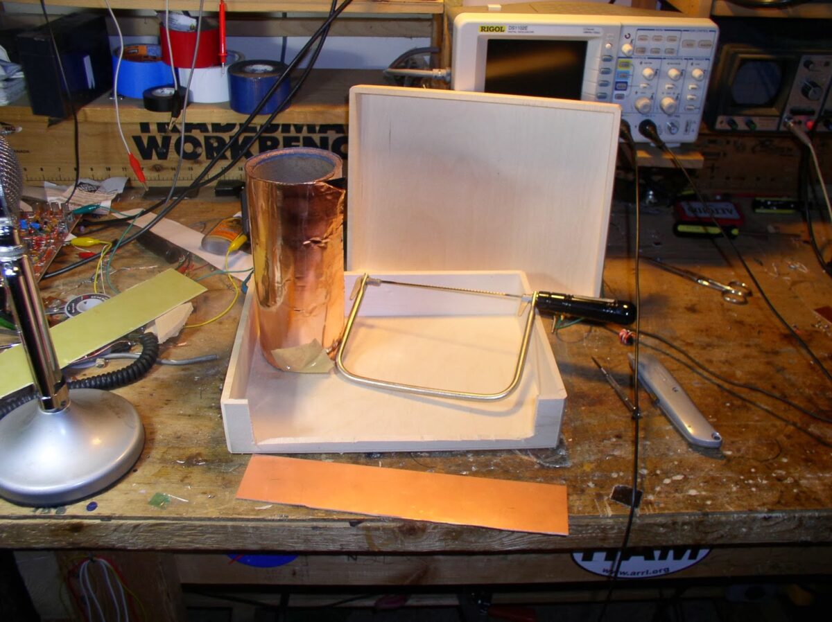
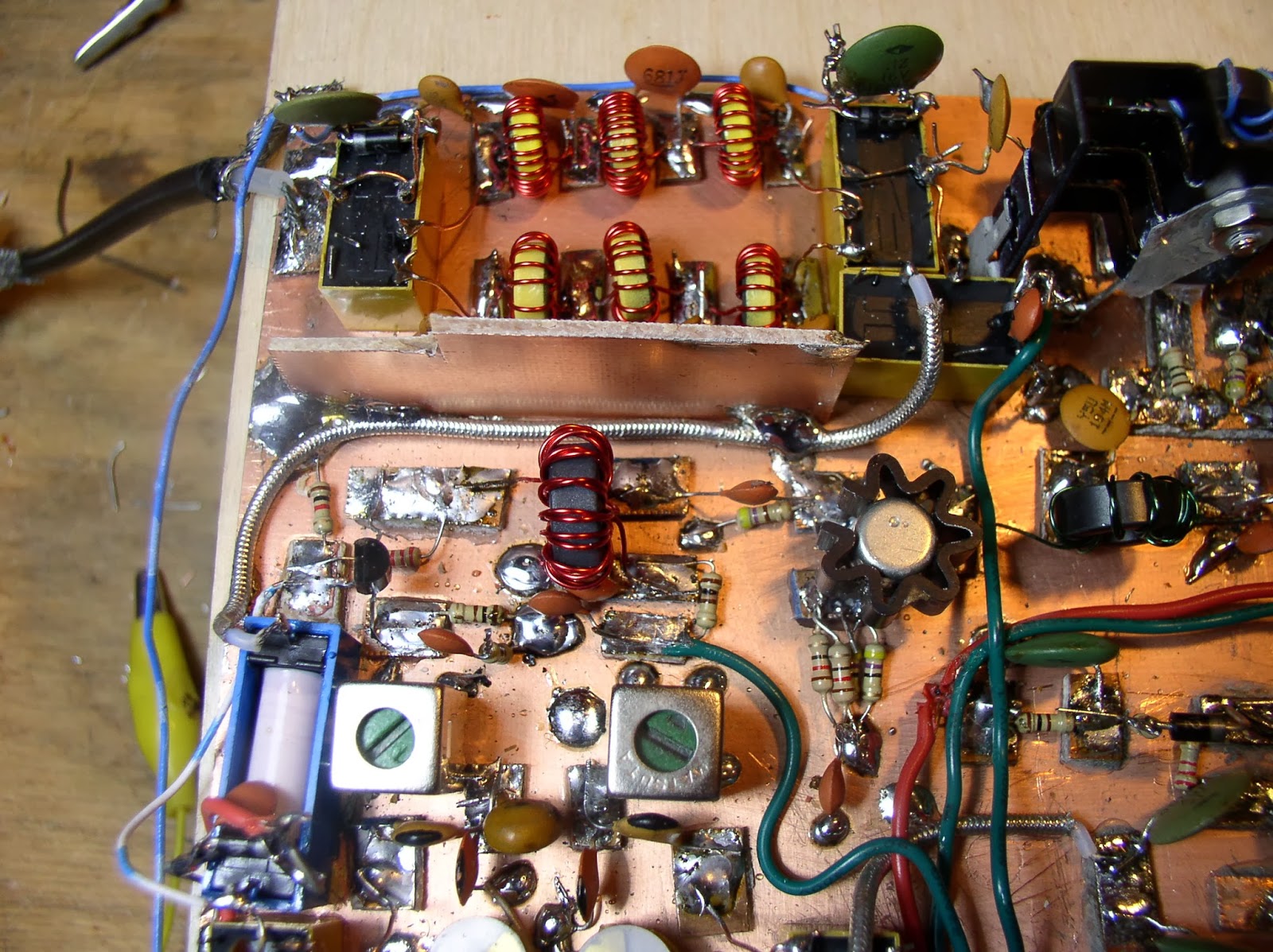
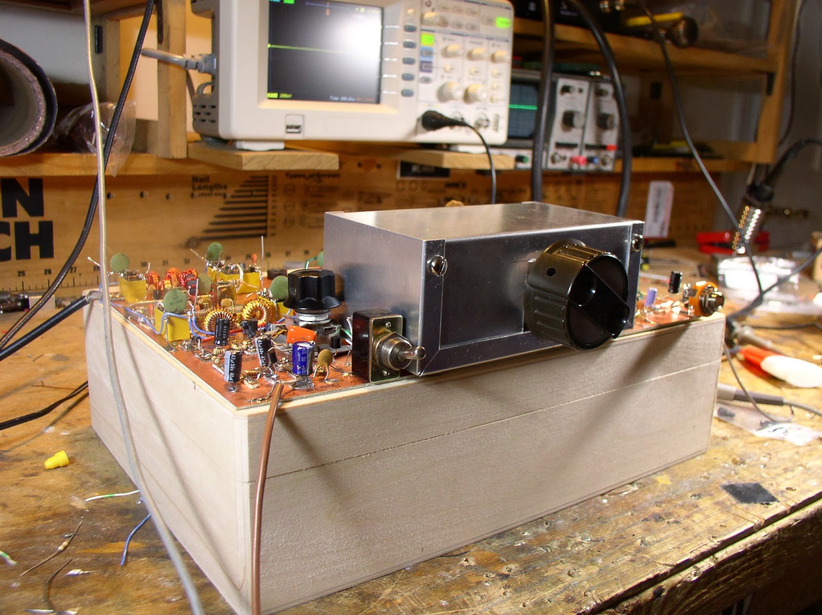
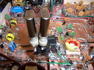
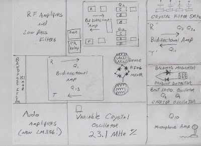
With the 20 Meter Oscillation Exorcism behind me, I have decided to take a break from electronics and do bit of woodwork. I took the walnut (I think) box that I bought via Amazon and cut out a big piece of the wood on the front. That’s where the rectangular piece of copper clad board will go — it will be the front panel, supporting the AF gain control, the bandswitch, the main tuning control, and the mic jack. A similar copper clad board will be on the back, this one supporting the antenna jack, speaker jack and 12V input jack (with space for a linear amplifier T/R control jack). (George Dobbs, G3RJV, calls this the “socketry.”)

That beautiful copper sheeting will line the inside of the box.

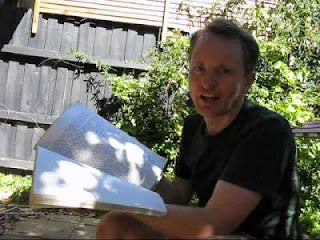
I found the soft wood on this box to be very easy to work with. The little saw pictured above made the woodwork easy.

I have boiled linseed oil and clear polyurethane for the finish.

Our book: “SolderSmoke — Global Adventures in Wireless Electronics” http://soldersmoke.com/book.htm Our coffee mugs, T-Shirts, bumper stickers: http://www.cafepress.com/SolderSmoke Our Book Store: http://astore.amazon.com/contracross-20

BITX20/40 Update #6: 20 Meter Exorcism


The transmitter was working fine on 40, but was horribly unstable on 20. In the past, this kind of thing would really drive me nuts, but experience has made me more patient. I know that “taming the beast” is part of the homebrew process.

I knew that layout was part of the problem: I had significantly less room on the board with this rig than I’d had with the BITX17: the additional bandpass filter and low pass filter, and the associated relays, used up a lot of copper clad real estate. So by the time I built the PA chain, the inputs were too close to the outputs.

The fact that the rig was stable on 40 but not on 20 led me to believe that this was not a problem of insufficient decoupling. Instead, I thought that I was getting additional inductive feedback at the higher frequency.

I noticed that the instability disappeared when I put the 1X scope probe on the input to the first amp in the RF chain (Q14). That was an important clue. Looking closely at the circuit, I realized that the base of Q14 had a long lead (several inches) up to the low pass filter. I had experienced problems with this lead on the BITX 17 project and had cured it with a relay at the low pass filter — this relay took one end of the lead out of the circuit on transmit, preventing it from becoming a little radiator. I used that mod in this rig, and figured that that cured the trouble. Wrong. The other end of that lead was still connected to the input to the RF power chain. It was picking up enough RF to send the PA chain into oscillation.

I put a SECOND relay at the other end of the line. That took it completely out of the circuit. And the instability disappeared. I fired up the rig and worked California on 20. Very satisfying.

Our book: “SolderSmoke — Global Adventures in Wireless Electronics” http://soldersmoke.com/book.htm Our coffee mugs, T-Shirts, bumper stickers: http://www.cafepress.com/SolderSmoke Our Book Store: http://astore.amazon.com/contracross-20

BITX 20/40 Build Update #5: It is ALIVE!

I got the BITX 20/40 on the air this morning. The receiver has been working for a week or so, but as usual it was a bit of a struggle to tame the transmitter. I got up early this morning and started poking and probing. I played with the driver and final coils a bit. I had used the same trifilar toroids that I’d used in the BITX 17, but this rig didn’t seem to like them. So I went with FT-50-37 bifilars — that seemed to work better. That IRF-510 seems to put out about seven watts on 40. (I still need to tame the transmitter on 20). The 40 meter signal looked great on the ‘scopes (RIGOL and Tek!). Shortly before 8 am I worked AD4SY who reported that I was filling his shack with booming audio. Life is good.

Our book: “SolderSmoke — Global Adventures in Wireless Electronics” http://soldersmoke.com/book.htm Our coffee mugs, T-Shirts, bumper stickers: http://www.cafepress.com/SolderSmoke Our Book Store: http://astore.amazon.com/contracross-20

SolderSmoke Podcast #158: BITX 20/40, Farhan’s “Minima”, BITX Bandsweep

SolderSmoke Podcast #158 is available:

http://soldersmoke.com/soldersmoke158.mp3

January 20, 2014
MLK Day. Tough winter. Shack heated by Heathkit.
BITX 20/40 Almost done:
Bandswitching arrangement.
VFO construction using spreadsheets.
2N2222s wired in backwards! (CBE not EBC! Who knew?)
Other amusing building errors.
Crystal filter evaluation — the G3UUR method.
Sweeping a filter with an Arduino DDS.
Building a BITX in LTSpice.
New Rigol ‘scope (now 100 MHz).
Tek 465 REBORN!
QRP HATERS — They are out there!
MAILBAG.
BITX 20/40 dual band bandsweep

Our book: “SolderSmoke — Global Adventures in Wireless Electronics” http://soldersmoke.com/book.htm Our coffee mugs, T-Shirts, bumper stickers: http://www.cafepress.com/SolderSmoke Our Book Store: http://astore.amazon.com/contracross-20

Bert’s Blog and BITX

Our friend Bert is once again melting solder. And he has launched a blog. (SolderSmoke listeners will remember Bert as the advisor to the University of Virginia radio club. That was the club that had its HQ in some sort of nuclear reactor building. They put up a huge wire antenna, but then took it down when they realized bike riders could possibly, uh, run into it.) Bert has some interesting stuff on his blog, including an article on conductive paint and one on the use of mail boxes as antenna tuner enclosures. And he reports that he has dusted off a BITX 20 kit. Welcome back Bert!

Check out his blog:
http://wf7ihomebrew.wordpress.com/

Our book: “SolderSmoke — Global Adventures in Wireless Electronics” http://soldersmoke.com/book.htm Our coffee mugs, T-Shirts, bumper stickers: http://www.cafepress.com/SolderSmoke Our Book Store: http://astore.amazon.com/contracross-20

BITX 20/40 BUILD UPDATE #4: 11MHz SSB Ladder Filter

As reported yesterday I have the 20 meter receiver portion of my BITX 20/40 rig up and running. I decided to take a closer look at the crystal filter I built.

Here is my method:

1) Using an Arduino/DDS sig generator, I put 11 Mhz energy into the base of Q2 (the stage immediately prior to the crystal filter).

2) Using my Rigol 1052E oscilloscope, I measured RMS voltage at the output of Q3/Q3A (the stage immediately following the filter).

3) I looked at Vrms as I MANUALLY varied the input frequency in 100 Hz increments.

4) I took the results and plugged them into a spreadsheet. I then used the spreadsheet to calculate the db drop from the peak Vrms value (So I wasn’t looking at insertion loss, just the filter shape).
I used 20*LOG(Vrms/276)

5) I ended up with the chart displayed above.

I have a few questions:
1) What do you folks think about my methodology for evaluating the filter?
2) Where would you guys put the BFO frequency?
3) I know the ripple looks ugly, but the receiver sounds great. Should I attempt to get rid of the ripple?

Here is the filter I used (as prescribed by the AADE software): I estimated Q at 10000 and used LM and CM values derived by the G3UUR method, and made no effort to match impedances going into the filter:

Here is what GPLA predicted. I estimated Rin and Rout values. That probably accounts for the difference between the GPLA prediction and what I measured.

Our book: “SolderSmoke — Global Adventures in Wireless Electronics” http://soldersmoke.com/book.htm Our coffee mugs, T-Shirts, bumper stickers: http://www.cafepress.com/SolderSmoke Our Book Store: http://astore.amazon.com/contracross-20

BITX 2040 Build Update #3 Receiver Sounds Great!

There it is, my second BITX transceiver, this one for 20 and 40. Once I got the VFO sorted out, this one went together very quickly. Obviously experienced gained on the first project was a big help.

I followed Farhan’s advice and characterized the 11 MHz crystals in the filter. Then I used the AADE filter design software to build a 3 KHz filter. Using my Arduino DDS signal generator and the new Rigol ‘scope, I was able to do a manual sweep across the passband — it looked very close to what was predicted by the software.

This morning I built the bandpass filter for 20. As soon as that was done, I fired up the receiver. This was an amazing experience for me: a homebrew receiver that worked right away! That never happened before. I’m listening to 20 meters now. It sounds great. I even managed to demodulate and display some SSTV. The VFO seems very stable.

I still have to build the RF amplifier stages, the bandpass filter for 40 and low pass filters for 20 and 40 (I know Steve Smith is watching!). Then it will be time for cabinetry. I guess I should put some paint or varnish on that walnut box. Any recommendations? I’ll line it (on the inside) with copper flashing material.

Our book: “SolderSmoke — Global Adventures in Wireless Electronics” http://soldersmoke.com/book.htm Our coffee mugs, T-Shirts, bumper stickers: http://www.cafepress.com/SolderSmoke Our Book Store: http://astore.amazon.com/contracross-20

Where to send all those LM386 chips: Make them BEAM robot brains!

Over in the BITX20 yahoo group there have been some comments about the shortcomings of the widely used LM386 audio amplifier chip. Many people don’t like it because it is noisy. I don’t like it because it is a chip. (In my BITX rigs I have replaced it with a simple discrete component audio amplifier.) So this morning I was pleased to find this video on the Maker blog that presents a very good use for all those LM386 devices: We can turn them into robot brains!

Make’s video and web page on this project are both very good. One paragraph in the page kind of captures the reasons I dislike the LM386:

How It Works

The core of the “Herbie” circuit is the LM386 power amplifier chip. To simplify a bit, we can think of the chip as a “black box” with inputs and outputs that respond in predictable ways, and don’t have to completely understand what’s going on inside.

http://makezine.com/projects/sunbeam-seeker-bot/

Our book: “SolderSmoke — Global Adventures in Wireless Electronics” http://soldersmoke.com/book.htm Our coffee mugs, T-Shirts, bumper stickers: http://www.cafepress.com/SolderSmoke Our Book Store: http://astore.amazon.com/contracross-20

11 MHz IF for new BITX 20/40 Dual Bander? Also: Cabinetry and Socketry

I am gathering parts and ideas for a BITX dual bander (20 and 40 meters). I know Farhan used a 10 MHz filter for his “Simple SSB Transceiver.” But I was thinking of going a bit higher, to 11 MHz. This would allow me to run the VFO from 3.175 to 3.355 for 20 meters, and 3.695 to 3.875 for 40 meters. I’m hoping that I can do this with one single VFO (Farhan used two VFOs), perhaps with a reed relay switching in some additional capacitance for the other band. I’ll also follow Farhan’s lead and switch the Low-Pass and Band-Pass filters with DPDT relays.

I set up a simple spread sheet and looked at the VFO harmonics to see if any fell within the desired tuning ranges. That looks OK. I have not looked at mixing products between VFO and BFO. What do you folks think? Would the 11 MHz IF for these bands work? Or are there evil birdies lurking in my future?

I’ve gone ahead and bought another wood box for the new rig (I didn’t even have to suffer through a second visit to the crafts store — they are available on Amazon). I also got a roll of copper sheeting at Home Depot. This time I will prepare the box first, lining the inside with copper and preparing all the “socketry” (George Dobbs’ word) before putting the PC board in.

Our book: “SolderSmoke — Global Adventures in Wireless Electronics” http://soldersmoke.com/book.htm Our coffee mugs, T-Shirts, bumper stickers: http://www.cafepress.com/SolderSmoke Our Book Store: http://astore.amazon.com/contracross-20

BITX Build Update #20 — Switchable Crystals, South Africa QSO

I got tired of popping the hood and manually changing my VXO crystals. First I tried to switch the rocks using a rotary switch on the front panel, but I think the leads were too long and the output was kind of squirrely. So I dug around in the junk box and found a 12 volt double pole double throw relay. I put the crystal sockets across the two poles and ran leads from the armature terminals to the crystal terminals. I use the rotary switch to activate the relay. I cover about 41 kHz of the 17 meter band with the two crystals.

17 meters has been in great shape. On November 16 I had a very nice contact with Syd, ZS1TMJ in Glenwilliam, South Africa. That’s about 8000 miles on 5 watts SSB.

Our book: “SolderSmoke — Global Adventures in Wireless Electronics” http://soldersmoke.com/book.htm Our coffee mugs, T-Shirts, bumper stickers: http://www.cafepress.com/SolderSmoke Our Book Store: http://astore.amazon.com/contracross-20

M0XPD’s Digital Analog BITX — Best of Both Worlds

Paul, M0XPD, has built a very interesting version of the BITX rig. His is on 40 meters. It features plug in bandpass and IF filters (great idea!) and uses DDS technology for both the BFO and VFO stages. Good going Paul! More details here:
http://m0xpd.blogspot.co.uk/2013/11/rising-to-challenge.html

Our book: “SolderSmoke — Global Adventures in Wireless Electronics” http://soldersmoke.com/book.htm Our coffee mugs, T-Shirts, bumper stickers: http://www.cafepress.com/SolderSmoke Our Book Store: http://astore.amazon.com/contracross-20

Standard Computer Crystals for 17 Meter SSB VXO and IF Filter

Pete Juliano, N6QW, is an electronic genius. The ideas in his SPRAT article will be of great use to all those who share in Doug DeMaw’s devotion to VXOs and reluctance to spend money. I’m really tempted to go back and re-do my BITX using Pete’s 11.52 MHz computer crystal super-VXO and 4.9152 IF (I could then take my expensive 23.1 MHz crystals and put them back in my Doug DeMaw Barebones Superhet). I also like Pete’s DPDT reed relay crystal switcher too. Three cheers for Pete Juliano, Doug DeMaw, and SPRAT! And thanks to WB9FLW for reminding us of Pete’s articles.

Hi Bill,

Your BITX17 really has me fired up! I came across an interested Super VXO by Pete N6QW for use on 17 Meters.

He uses standard computer xtals (4.9152 MHz for the IF) and (3 – 11.520 MHz freq doubled in the VXO)

This gets you on 18.120 to 18.150 using these two standard xtals.

See Link Below:

http://www.jessystems.com/SPRAT%20Article.pdf

https://www.homebrewradio.us/blog/wp-content/uploads/2013/11/2320MHz20VXO.jpg

Thanks for all your efforts they are much appreciated!!

Best Wishes,

Pete WB9FLW

Our book: “SolderSmoke — Global Adventures in Wireless Electronics” http://soldersmoke.com/book.htm Our coffee mugs, T-Shirts, bumper stickers: http://www.cafepress.com/SolderSmoke Our Book Store: http://astore.amazon.com/contracross-20

BITX Build Update #19 Layout, VXO, Bal Mod, Filter, PA

The files of the BITX20 Yahoo group were very useful to me during my BITX build. So I have decided to make a contribution myself. I uploaded a few drawings today. Here is how I laid out the circuitry on my 8 inch by 11 inch copper clad board. I included the isolation (Manhattan) pads for one of the bidirectional amps.

Here is the VXO. I built is on a separate board, but I could have put it on the main board.

Here is the balanced modulator and crystal filter.

Here is the power amplifier circuitry. Amazingly easy to stabilize.


Our book: “SolderSmoke — Global Adventures in Wireless Electronics” http://soldersmoke.com/book.htm Our coffee mugs, T-Shirts, bumper stickers: http://www.cafepress.com/SolderSmoke Our Book Store: http://astore.amazon.com/contracross-20

BITX (and W2AEW) on Hack-A-Day

The guys over on Hack-A-Day ran a little follow-up article on the BITX-17. Check it out:
http://hackaday.com/2013/11/13/bitx-a-return-to-hackers-paradise/#comments

They also had an article about Tek-Wizard Alan Wolke earlier in the week:
http://hackaday.com/2013/11/11/diagnose-and-repair-a-yaesu-ft-7800-ham-radio/

Our book: “SolderSmoke — Global Adventures in Wireless Electronics” http://soldersmoke.com/book.htm Our coffee mugs, T-Shirts, bumper stickers: http://www.cafepress.com/SolderSmoke Our Book Store: http://astore.amazon.com/contracross-20

That wonderful first contact, when the new HB rig is still on the workbench…

In this video, YC0AFF in Indonesia seems to be having as much fun with his new BITX as I’ve been having with mine. I think there is something special about those early contacts, when the newly finished (or not quite finished!) rig is still on the workbench. Designed in India and built by radio amateurs all around the world, the BITX has become a global ham radio phenomenon, reminding us that we form an International Brotherhood of Electronic Wizards.

Our book: “SolderSmoke — Global Adventures in Wireless Electronics” http://soldersmoke.com/book.htm Our coffee mugs, T-Shirts, bumper stickers: http://www.cafepress.com/SolderSmoke Our Book Store: http://astore.amazon.com/contracross-20

SolderSmoke Podcast #156 — Special Echolink Interview

Podcast #156 is available:
http://soldersmoke.com/soldersmoke156.mp3

Special hour-long interview with Peter Parker, VK3YE
— Early experiences with radio
— CW
— DSB Gear
— Simple gear, and gear that is TOO simple
— VXOs, Super VXOs and Ceramic Resonators
— Building receivers
— Chips vs. Discrete
— Making the leap to SSB
— The Knob-less wonder and the BITX
— No need for a sophisticated workshop
— Advice for new phone QRPers

Our book: “SolderSmoke — Global Adventures in Wireless Electronics” http://soldersmoke.com/book.htm Our coffee mugs, T-Shirts, bumper stickers: http://www.cafepress.com/SolderSmoke Our Book Store: http://astore.amazon.com/contracross-20

BITX Build Update #18 — BITX in a Box?

I’ve really been enjoying using my BITX17 without an enclosure. Having all the electronics exposed on the workbench really accentuated the homebrew nature of this rig. But obviously it was time to box this thing up. At a local craft store, I found a wooden box that is exactly the right size for my BITX copper clad board. I put the BITX in the box yesterday. I kind of miss the exposed electronics.

The far left control is AF gain. The need for a few inches of wire to the pot has introduced a bit of AC hum. I’ll try to knock this down with better shielding on the lead to the pot.

But this gets brings us too a bigger question: the need for a cabinet that shields. Obviously the wood shields it only from dust. I know there are some benefits to putting this thing in a proper metal box. The AC hum would be less of a problem. Also — listen to this — in the morning, before 17 opens, I can hear — faintly — the WWV transmission on 5 MHz (recall that the IF in this rig is 5 MHz). And if I ever build an external linear amp for this rig (I might), I guess a proper metal box would help prevent the kind of oscillation that often drives me crazy on these kinds of projects.

So, what do you guys think? Stick with the wood, or put it in a metal box? Any thoughts on putting metal shielding material around the inside of the box (thick aluminum of tin foil)?

(The other black control knob is for a rotary switch that will allow me to select among two or three crystals for the VXO. )

Our book: “SolderSmoke — Global Adventures in Wireless Electronics” http://soldersmoke.com/book.htm Our coffee mugs, T-Shirts, bumper stickers: http://www.cafepress.com/SolderSmoke Our Book Store: http://astore.amazon.com/contracross-20

Slide Show of BITX 17 Build

As I was building this rig, I periodically stopped and took a picture of the board. I think the resulting slide show is kind of fun. Check it out: There is a button to launch the slide show.

http://www.flickr.com/photos/106886073@N04/sets/72157637045750216/

Our book: “SolderSmoke — Global Adventures in Wireless Electronics” http://soldersmoke.com/book.htm Our coffee mugs, T-Shirts, bumper stickers: http://www.cafepress.com/SolderSmoke Our Book Store: http://astore.amazon.com/contracross-20

BITX BUILD UPDATE #17 Arv’s Discrete AF AMP

I’ve been kind of cheating with the audio output from my BITX17: I’ve been using one of those little battery-powered computer speakers. It sounded fine, but hey, this is supposed to be a homebrew project right? I’ve already noted my ideological objections to the use of the LM386 CHIP. The files of the BITX20 yahoo group provided a very promising and completely discrete AF amp circuit by Arv Evans, K7HKL. I used a 2N3906 and a 2N3904, with a 2N2222 driving them. It works like a charm. Not a bit of feedback or motor-boating. It sounds great. I’ve already had a contact with it: Jack, W7YUM is a builder of big amplifiers out in Salt Lake City. He seemed very impressed with the BITX concept so we may have a Utah BITX in the works.

book: “SolderSmoke — Global Adventures in Wireless Electronics” http://soldersmoke.com/book.htm Our coffee mugs, T-Shirts, bumper stickers: http://www.cafepress.com/SolderSmoke Our Book Store: http://astore.amazon.com/contracross-20

BITX BUILD UPDATE #16 — FIRST QSO!!!!!!!!!!!

Wow, it is very clear that the radio gods are pleased with my BITX efforts! I had my first QSO on the new rig today. And it was with a station in my old home, the place where I got my start in 17 meter homebrew phone: THE AZORES! CU7MD. Very cool.

Our book: “SolderSmoke — Global Adventures in Wireless Electronics” http://soldersmoke.com/book.htm Our coffee mugs, T-Shirts, bumper stickers: http://www.cafepress.com/SolderSmoke Our Book Store: http://astore.amazon.com/contracross-20