A New Look at BITX Carrier Suppression; N6QW IN EMRFD!

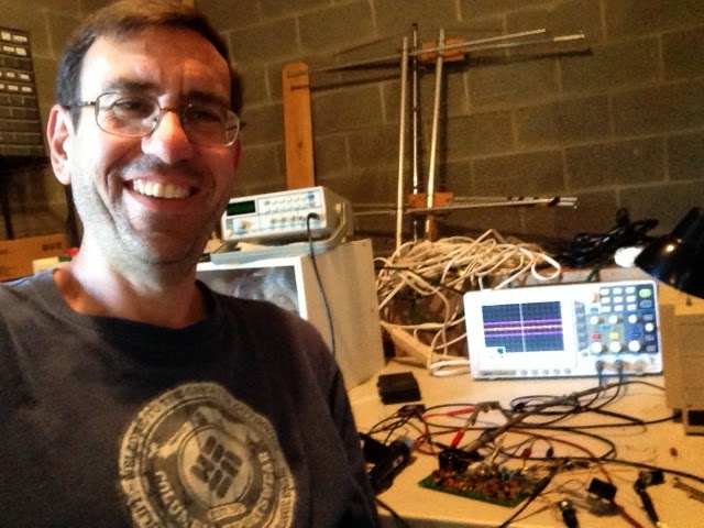
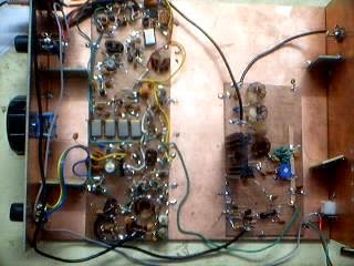
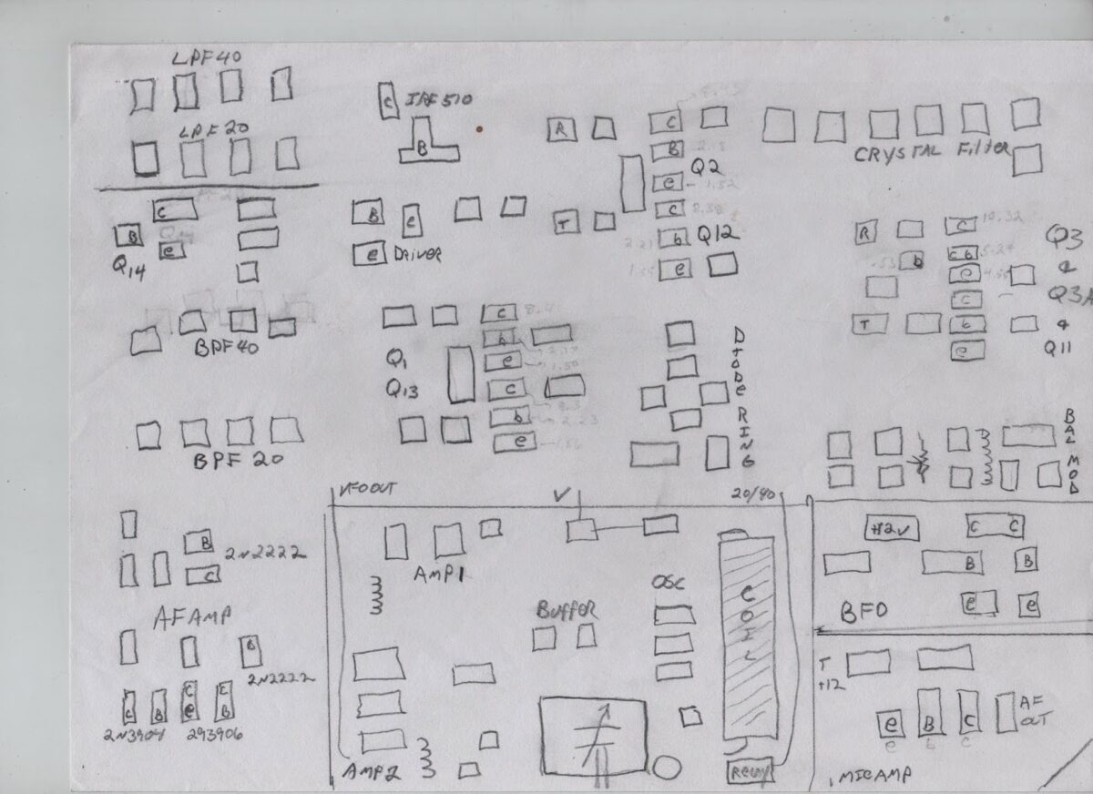
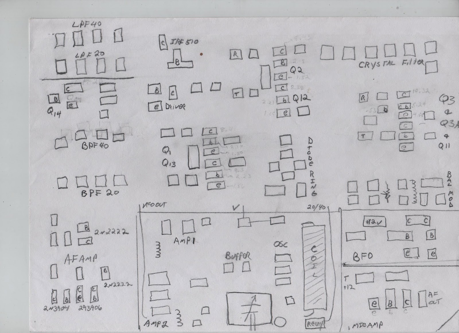
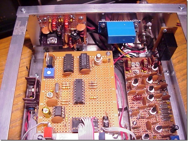
Bert, WF7I, was recently struggling to get his BITX 20 going and he asked some good questions about carrier suppression. I realized that I hadn’t really paid much attention to this. Perhaps as a result of my long experience with DSB, I was happy as long as I was able to null out MOST of the carrier.

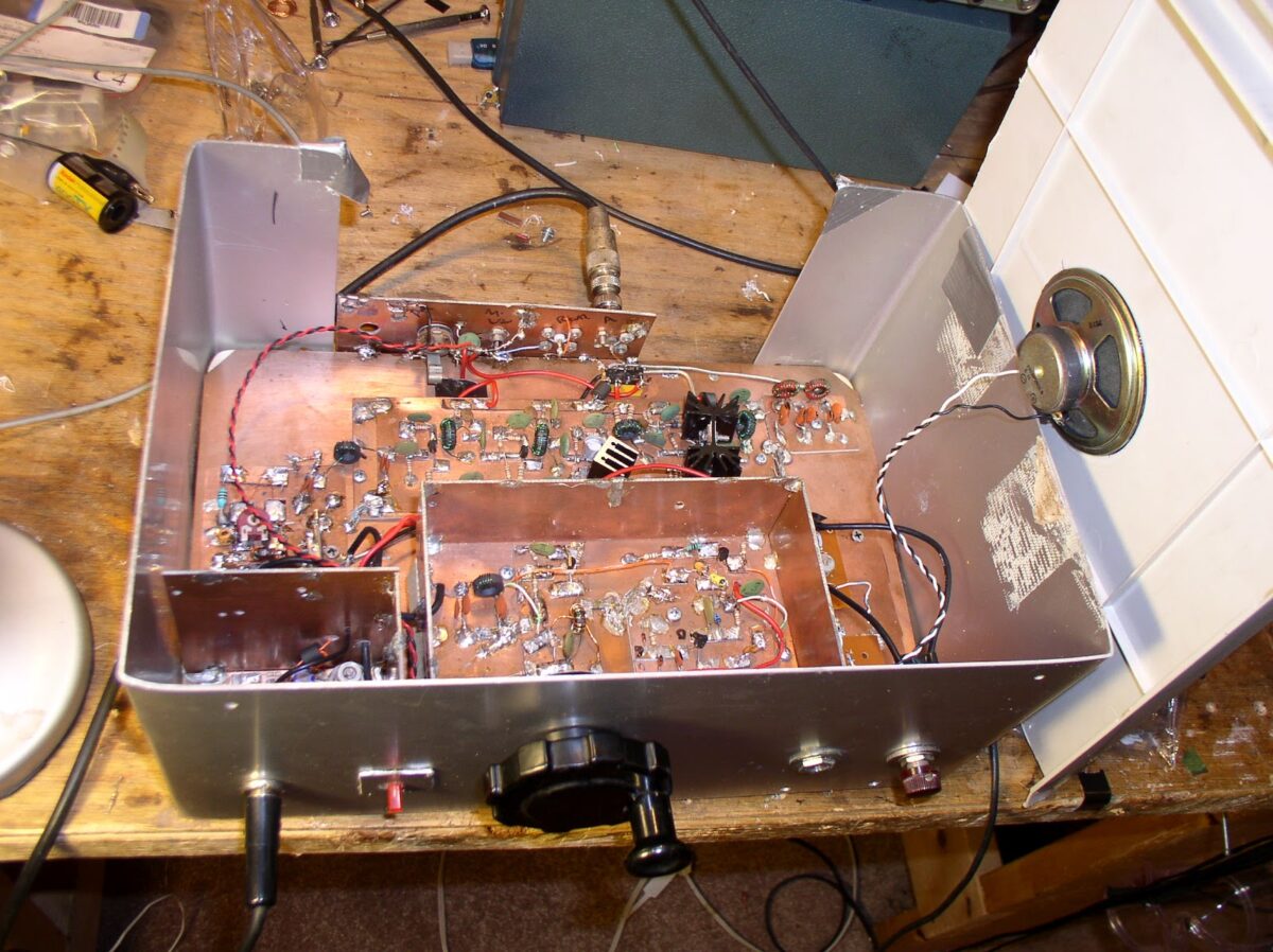
I fired up the scope and took a look at the output from the BITX 2040 on 40 meters. Here’s the test setup: Coax from the antenna terminal to a 50 ohm resistive load at the Rigol O’scope probe. Just keying the transmitter (no mic connected), carrier was at 980 millivolts rms or about 19 milliwatts. I then connected an AF sig generator into the mic in connector and pumped in some 1000 Hz sine wave. Peak output was 20.7 volts rms, or about 8.6 watts. That puts the carrier about 27 db down. I felt I should be doing better.

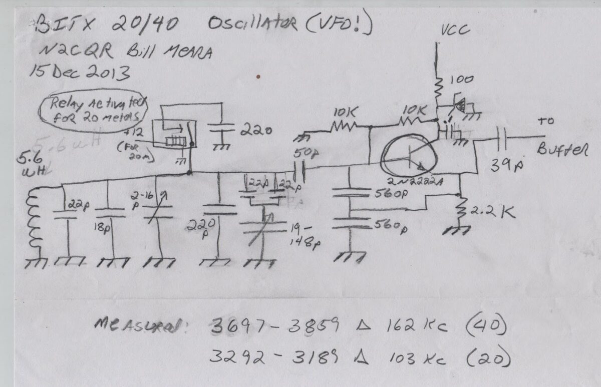
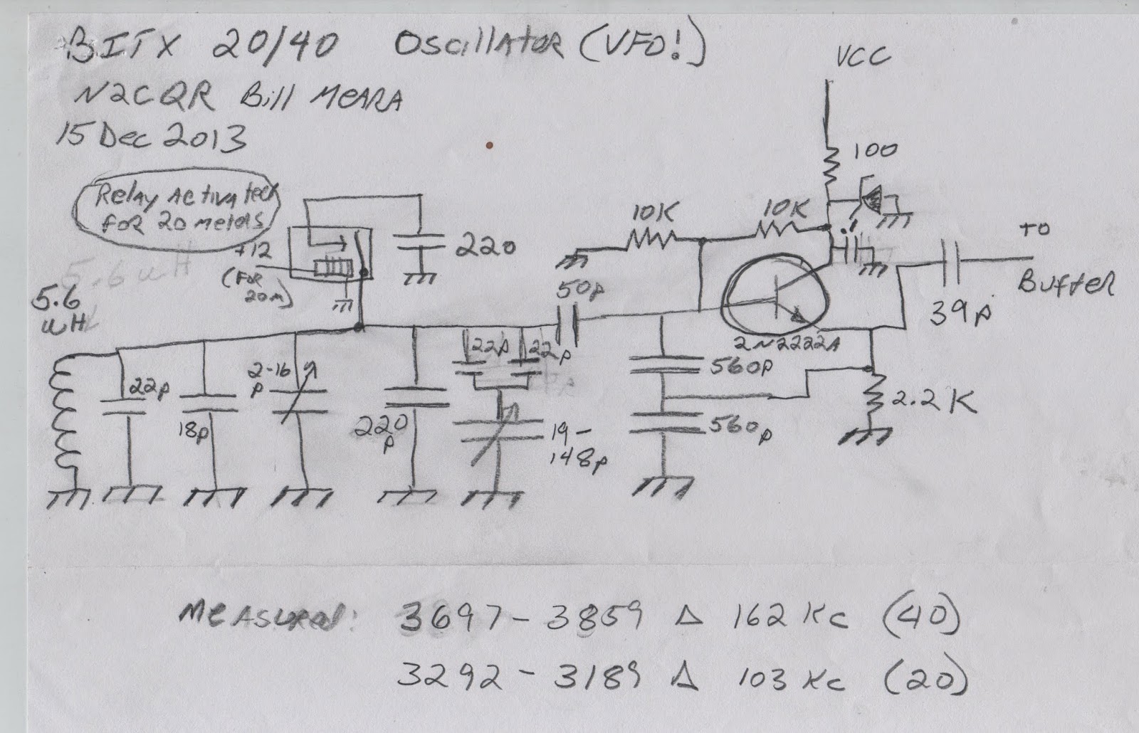
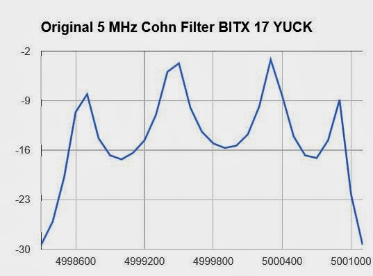
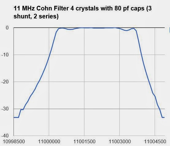
I took a look at the shape of my crystal filter and the frequency placement of my carrier oscillator. I noticed that the carrier oscillator freq was fairly close to the bandpass portion of the crystal filter — fairly high up the skirt, only about 9 db below the passband level. I figured that if I just moved that carrier oscillator up around 300 Hz, I would get around 10 db of additional carrier suppression.

Sure enough, with the carrier moved a mere 300 Hz further away from the passband, the residual carrier dropped to 346 millivolts rms, or about 2.4 milliwatts. Now peak output was 20.9 volts rms, or 8.7 watts. 36 db of carrier suppression.

I guess I could do better if I moved the carrier up another little bit, but I like the sound of it now. I may have been able to better if I’d fiddled with the balanced modulator diodes a bit more. But what do you guys think? Should I worry about 2 milliwatts of residual carrier? Heck I once ran a CW rig (W1VD’ VXO 6 watter) that kept the oscillator running on key up, producing about 15 mw of “backwave.” No damage was done, few noticed, no one complained.

Oh yea, is this the way to measure carrier suppression?

—-

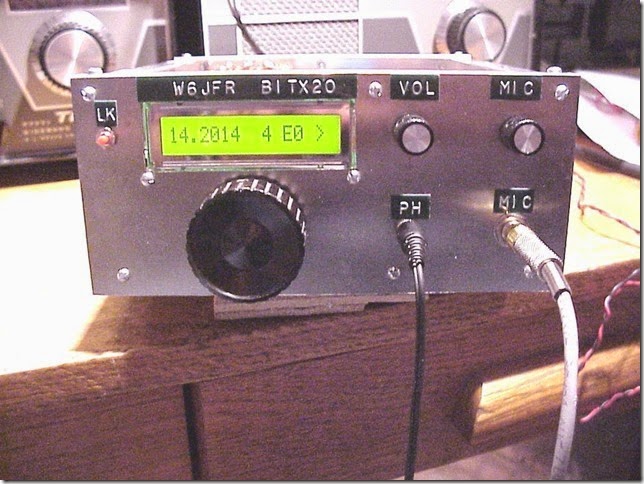
While doing all this, I pulled out my trusty copy of EMRFD. The index led me to the balanced modulator section on page 6.56. There I spotted a familiar call: W6JFR!!! That’s Pete Juliano, N6QW! Pete is credited with a mod to the SBL-1 mixer that adds a balance control pot to the device. Wow, actually being IN EMRFD fully confirms Pete’s homebrew guru status.

Our book: “SolderSmoke — Global Adventures in Wireless Electronics” http://soldersmoke.com/book.htm Our coffee mugs, T-Shirts, bumper stickers: http://www.cafepress.com/SolderSmoke Our Book Store: http://astore.amazon.com/contracross-20

Bert WF7I Finishes BITX, WORKS ITALY

That, my friends, is the look of exhausted contentment that comes after you have FINALLY gotten your new homebrew rig to work, and were rewarded by crossing the mighty Atlantic on your first call. Congrats Bert! Details here:


Our book: “SolderSmoke — Global Adventures in Wireless Electronics” http://soldersmoke.com/book.htm Our coffee mugs, T-Shirts, bumper stickers: http://www.cafepress.com/SolderSmoke Our Book Store: http://astore.amazon.com/contracross-20

BITX 5 Watter Makes the Trip to Tokyo

The solar flux index was only 151 this morning, but grey line conditions to Japan were very good. Yoshi, JA1OJJ, was booming in on 17 meters. We had a nice chat. He said I was 55. His 5 element quad helped a lot!

Our book: “SolderSmoke — Global Adventures in Wireless Electronics” http://soldersmoke.com/book.htm Our coffee mugs, T-Shirts, bumper stickers: http://www.cafepress.com/SolderSmoke Our Book Store: http://astore.amazon.com/contracross-20

F6FEO’s BITX 20 (and DSB Rig)

This morning I was looking at F6FEO’s wonderful web site (Frank, KM4AXA is building the 28 Mhz DSB rig from Michel’s site) . The drawings have a nice JF1OZL feel to them.

Check out Michel’s site. Just hit the translate button if you have trouble with the French language:
http://f6feo.homebuilder.free.fr/index.html

Merci Michel!

Our book: “SolderSmoke — Global Adventures in Wireless Electronics” http://soldersmoke.com/book.htm Our coffee mugs, T-Shirts, bumper stickers: http://www.cafepress.com/SolderSmoke Our Book Store: http://astore.amazon.com/contracross-20

Video of Pete Juliano’s 20-40 Bilateral Rig

Wow, what a beautiful rig. Nice work Pete. Kind of eerie how we both chose the 20/40 combination after building 17 meter rigs. We’ll have to talk more about this in SolderSmoke 162. Soon!

Our book: “SolderSmoke — Global Adventures in Wireless Electronics” http://soldersmoke.com/book.htm Our coffee mugs, T-Shirts, bumper stickers: http://www.cafepress.com/SolderSmoke Our Book Store: http://astore.amazon.com/contracross-20

Parts Cost for BITX in India: $5 US (that’s buying all the parts!)


I knew that in India you could build a BITX for a few bucks, but I thought that this cost estimate assumed a fairly well-stocked junk box. Not true! This morning an e-mail from Farhan points out that even if an Indian ham has to BUY all the parts, he can get all of them for the equivalent of 5 dollars U.S.:

“Less than half a cent per resistor, less than a cent per capacitor, two cents per npn transistor and 50 cents for the IRF510. We use ‘tv baluns’ and tap washers for coils.”

And, from the original BITX design page:

The purpose is to address the need among Indian hams in particular for an SSB rig that is easily and cheaply built. My original aim was to keep the price under Rs. 1000. The current design brings the cost to well under Rs.300 (less than 7 dollars).”

Now, when you are talking to someone using a new $10,000 Yaesu/Icom/Kenwood rig, it might be a bit unkind to mention that your rig can be had for $5.

Our book: “SolderSmoke — Global Adventures in Wireless Electronics” http://soldersmoke.com/book.htm Our coffee mugs, T-Shirts, bumper stickers: http://www.cafepress.com/SolderSmoke Our Book Store: http://astore.amazon.com/contracross-20

VFO for BITX 20/40

Here’s the VFO I use in my BITX 20/40. IF is obviously 11 MHz. VFO normally tunes 3697-3859 kHz for 40 meters. Switching in that 220 pf cap lowers the range to 3292-3189 kHz for 20 meters. It workd very well. The coil is wound on a cardboard tube from a coat hanger. I will put this in the appropriate file on the BITX group site. I like the 20/40 band combination: Good DX possibilities on 20, with provisions (40!) for the low sunspot counts to come.

Our book: “SolderSmoke — Global Adventures in Wireless Electronics” http://soldersmoke.com/book.htm Our coffee mugs, T-Shirts, bumper stickers: http://www.cafepress.com/SolderSmoke Our Book Store: http://astore.amazon.com/contracross-20

Manhattan meets Hyderabad: Pad Pattern for my BITX 20/40

A rough guide to how I laid out the isolation pads on my BITX 20/40 board. The copper-clad board is 8 inches x 11 inches (22 cm x 28 cm). I just cut out the pads as needed using tin shears and scrap pieces of copper clad board. Gorrilla SuperGlue is my preferred adhesive. I will put this in the appropriate file on the BITX 20 yahoo group site.

Our book: “SolderSmoke — Global Adventures in Wireless Electronics” http://soldersmoke.com/book.htm Our coffee mugs, T-Shirts, bumper stickers: http://www.cafepress.com/SolderSmoke Our Book Store: http://astore.amazon.com/contracross-20

Pete Juliano’s Bilateral Rigs (with videos)

Hi Bill,
I was finally getting around to reading one of the recent SPRAT’s and saw a photo of your magnificent BITX17. Congratulations! A tip of the hat to Farhan for that very excellent design and it truly is a design that has traveled the world and made a radio available to many who otherwise would not be on the air.
It is a very robust design as I scratch built one in 2005 (or maybe 2006) and just for fun socketed every transistor so I could try various devices. I even had a bag of 2N706’s dating back to the late 1960’s. They all worked except for the carrier oscillator where I just couldn’t get enough swing in the oscillator to correctly place the CIO on the filter slope. That I attribute to the junction capacitance of the 2N706. By far the lowly 2N3904 that I bought for 4 cents each worked the best. Back when I built this I was W6JFR. Adding the EI9GQ frequency stabilizer really added a nice touch to the radio.
I should also tell you that when I built the radio my intent was to uses a piece of single sided copper vector board for the main chassis. It was the weekend and I didn’t realize the piece I had was not big enough for the project. So I took a piece of standard perf board and overlaid that on top of a piece of single sided copper PC board –AND hand drilled all of the holes – I went blind, cross-eyed and had a terrible hangover after consuming 6 beers in a short time span! See the photos below.
BTW I also built a 17M SSB transceiver using the bilateral amp stage from G4GXO as appeared in the SPRAT 128. That used a 4.9152 MHz IF and a 23 MHz Super VXO. In the case of the VXO I used 11.52 MHz crystals in the VXO and used a diode doubler to put the LO at 23 MHz. With the doubler –you get the bonus of 2X the frequency shift of the Super VXO. I also had made a custom set of crystals and used a small relay to switch those into the circuit and that essentially gave me almost the full SSB Band coverage. You can see that here
Also I have been using a simple bilateral stage consisting of a 2N3906 and 2N3904 and the results have been amazing. The latest work is a follow on to my shirt pocket transceiver and uses SMD components. See attached.
Here are some videos of the latest –which is now a two bander 40 and 20M. (Originally it was 75 and 40M)
Have fun – this is such a wonderful hobby!
73’s
Pete N6QW

Our book: “SolderSmoke — Global Adventures in Wireless Electronics” http://soldersmoke.com/book.htm Our coffee mugs, T-Shirts, bumper stickers: http://www.cafepress.com/SolderSmoke Our Book Store: http://astore.amazon.com/contracross-20

VU2JN’s “Transistor Transmitter from India”

VU2JN

VU2INJ’s very interesting blog led me to a wonderful 1967 QST article by VU2JN. Check it out. Necessity truly is the mother of invention and — as is the case with our beloved BITX — we see that in the design of this transmitter. I love how the speaker was left in the cabinet and used as the microphone. Check it out:

http://vu3inj.blogspot.in/2014/01/tribute-to-vu2jn.html

More on VU2JN (who very clearly merits “Homebrew Hero” status):

http://shipwreck1.hopto.org:8080/projects/hamprojects/VU2JNArchive/

Our book: “SolderSmoke — Global Adventures in Wireless Electronics” http://soldersmoke.com/book.htm Our coffee mugs, T-Shirts, bumper stickers: http://www.cafepress.com/SolderSmoke Our Book Store: http://astore.amazon.com/contracross-20

The Wizard of Sao Paulo

It has been about 4 years since Miguel, PY2OHH, has been mentioned in this blog. That’s too long! Miguel has churned out an impressive series of homebrew rigs, the latest of which he calls the Baita Tche. Does that name look familiar? It is a play on words using slang from Southern Brazil. “Baita” means big or enormous. “Tche” means “you.” Together they sound sort of like BITX! Miguel has been building BITX rigs and rigs (like Baita Tche) similar to Farhan’s rig. Here is his page on Baita Tche:
http://py2ohh.w2c.com.br/trx/baitatche/baitatche.html

Here is his home page with a LONG (almost JF1OZL-ish!) list of projects:
http://py2ohh.w2c.com.br/

Here’s his YouTube channel:
http://www.youtube.com/user/py2ohh

Here’s a Photostream of some excellent Brazilian homebrew:
http://www.flickr.com/photos/py2jcm/2066764415/in/photostream/

Muito obrigado Miguel!

Our book: “SolderSmoke — Global Adventures in Wireless Electronics” http://soldersmoke.com/book.htm Our coffee mugs, T-Shirts, bumper stickers: http://www.cafepress.com/SolderSmoke Our Book Store: http://astore.amazon.com/contracross-20

Farhan’s RM386 RF Amplifier

An RF amplifier inspired by a quest for an AF replacement for the LM386. I like it! Check it out:

http://www.hfsignals.org/index.php/RF386

Our book: “SolderSmoke — Global Adventures in Wireless Electronics” http://soldersmoke.com/book.htm Our coffee mugs, T-Shirts, bumper stickers: http://www.cafepress.com/SolderSmoke Our Book Store: http://astore.amazon.com/contracross-20

Some notes on the Herring Aid 5


Sure, this receiver is not “state of the art.” But that’s the whole point. I wanted to finish the receiver project that I couldn’t finish back in 1976.

I tried to stick as close as possible to the original design and parts. NORCAL came up with an updated schematic in 1998 with parts that are more readily available. But Designer Jay Rusgrove was shooting for something that could be built with all the parts coming from Radio Shack. I think that is probably one of the factors that attracted me to the project way back when. That’s why Jay went with varactor tuning (no hard-to-get variable caps!). And that’s why he used coils that were wound on Radio Shack 10uH RF chokes (no need for hard-to-find toroidal cores). In this sense there is some common ground between the BITX rigs and the Herring Aid 5.

I stuck with the RF-choke as a coil idea for the VFO, but went with the NORCAL-prescribed toroids for the front end and mixer coils. (I may go back and try to use chokes in these circuits, but I’m not sure my junk-box will yield the kind of RF chokes that Jay used).

I wish I had known a few things when I was building this back in 1976: More knowledge about how to wind the coils would have been a big help. I wish I had realized that I could use a SW receiver to get the oscillator on the right frequency. I guess this was in the days before Ugly and Manhattan building techniques, but it would have been nice to know that there was no need to actually etch a board for this project (I did!).

The coils really are a bit tricky. Jay didn’t use any trimmer caps, so I guess you had to just hope that the front end coil and cap resonated somewhere near 40 meters. As for tuning the oscillator, Jay recommended scrunching and un-scrunching the turns on the RF choke. Yikes! Give me some trimmer caps!

I also found that you have to watch the level of the RF going from the oscillator to the mixer. Too much, and the receiver is deaf. Too little, same result. You need to experiment a bit with the number of turns on the pick-up coil from the oscillator.

The warnings about the pitfalls of that single BJT mixer were right on the mark: Lots of AM SW breakthrough. But I kind of like the background music. Strong RFI from local FM broadcast stations was another story (WMZQ is a country music station!). I reached into my junkbox and found a low-pass filter from a Heathkit DX-60. I just put that between the antenna and the receiver and the country music was GONE!

I really love this little receiver. I have it playing 40 meter CW as I type. It sounds great. I feel the urge to built a Tuna Tin 2 and put both of them on 40.

In the original Tuna Tin 2 article, Doug DeMaw notes that Jay Rusgrove was thinking of doing a companion receiver and says that he was thinking of calling it the “Clam Can 5” ! There were jokes about receivers for hams with “tin ears” and about there being “something fishy” about these rigs.

Thanks to Doug DeMaw and Jay Rusgrove and QST for bringing us these little circuits.

Our book: “SolderSmoke — Global Adventures in Wireless Electronics” http://soldersmoke.com/book.htm Our coffee mugs, T-Shirts, bumper stickers: http://www.cafepress.com/SolderSmoke Our Book Store: http://astore.amazon.com/contracross-20

Links Fixed, Podcast Version of Hamfest Presentation

Armand, WA1UQO, with BITX 17

Using Dropbox to post the video of my BITX presentation at the hamfest didn’t work out too well, so I put it on Vimeo:

https://vimeo.com/87725154

The slideshow is here: http://soldersmoke.com/winterfest.pptx

I stripped out the audio for those who would like to dispense with the video.

Audio only is here:

http://soldersmoke.com/soldersmokewinterfest.mp3

73

Our book: “SolderSmoke — Global Adventures in Wireless Electronics” http://soldersmoke.com/book.htm Our coffee mugs, T-Shirts, bumper stickers: http://www.cafepress.com/SolderSmoke Our Book Store: http://astore.amazon.com/contracross-20

Hamfest Presentation on SolderSmoke and BITX (Video)

The Vienna Wireless Society of Northern Virginia asked me to give a talk at their 23 Feb 2014 hamfest. I spoke about homebrewing and the BITX transceivers. Click on the link below to watch the video. (Special thanks to Elisa for doing the video.)

https://vimeo.com/87725154

The Powerpoint slides are here:

http://soldersmoke.com/winterfest.pptx

For those who just want to listen podcast style, I will try to turn the audio into a podcast and will post it via the normal channels.

Our book: “SolderSmoke — Global Adventures in Wireless Electronics” http://soldersmoke.com/book.htm Our coffee mugs, T-Shirts, bumper stickers: http://www.cafepress.com/SolderSmoke Our Book Store: http://astore.amazon.com/contracross-20

Tuna Tin Mojo Transferred to BITX17!!!!!!

It happened at the Vienna Wireless Society’s Winterfest Hamfest today in Northern Virginia.
That is Doug DeMaw’s original Tuna Tin.
This may be the first time TT Mojo has been given to a phone rig.
Doug DeMaw would, I’m sure, approve.

Thanks Rex!

Our book: “SolderSmoke — Global Adventures in Wireless Electronics” http://soldersmoke.com/book.htm Our coffee mugs, T-Shirts, bumper stickers: http://www.cafepress.com/SolderSmoke Our Book Store: http://astore.amazon.com/contracross-20

BITX 17 Build Update: More Filter Maintenance

Having had great success in straightening out the 11 MHz filter in my BITX 2040 (scroll down for details), today I decided to see what I could do with the filter in my 17 meter BITX (four 5 MHz crystals in Cohn MIN LOSS configuration, with 40 pf caps all around). The key to my success in all this has been the filter programs that came with EMRFD. After characterizing my crystals with the G3UUR method, I plugged the values into LADBUILD 8, then took a look at the expected results. As you can see from the image above the predictions were not pretty. Yuck. Lots of ripple and lots of insertion loss.

I went into the rig and using my DDS sig generator and my RIGOL ‘scope, measured actual performance. It looked worse than the prediction (part of the worsening is a difference in vertical scale):

LADBUILD lets you play around with the values of the components in the filters. I know that ripple is usually related to an impedance mismatch. So in LADBUILD I experimented (virtually) with different impedance values at the end. I noticed that at about 1000 ohms, the ripple and insertion loss got better:

So I went and built two broadband toroidal transformers. 4 turns primary with 12 turns secondary (1:9 Z). I’m assuming that the BITX has around 150 ohms at either end of the filter. That would put about 1350 ohms at the ends of the filter.

Here are the results:

Much better.

Our book: “SolderSmoke — Global Adventures in Wireless Electronics” http://soldersmoke.com/book.htm Our coffee mugs, T-Shirts, bumper stickers: http://www.cafepress.com/SolderSmoke Our Book Store: http://astore.amazon.com/contracross-20

BITX 2040 Build Update #10 : Fixing my Filter

That dip on the high side of the passband was bothering me. The GPLA crystal design program predicted it, and indeed, when I measured the performance of the actual filter, there it was. The rig was working fine — the receiver sounded fine and everyone tells me that it sounds great on transmit. But still, it bothered me.

So I started working out with the various crystal filter software packages.

This filter was — sort of — a Cohn Min-loss filter, but I had built it with four crystals and three shunt caps (80 pf each) and no series caps at the input/output. This morning I decided to see what would happen if I put the series caps in there. Here is what Wes’s GPLA predicted:

Wow, that looked a lot nicer. And the 150 ohm terminations seemed to be just about perfect for the BITX design — no need for impedance transformation. I heated up the soldering iron and searched the junkbox for suitable caps (I found 2 82 pf caps — close enough).

Here is what the results looked like (I didn’t measure insertion loss so the top of the curve is just the peak of the response curve).


Exactly as predicted! Thanks Wes! And thanks to Farhan for encouraging me to characterize my crystals and to use the available software

Now I have to go back and de-ripple the 5 MHz filter in my BITX 17.

Our book: “SolderSmoke — Global Adventures in Wireless Electronics” http://soldersmoke.com/book.htm Our coffee mugs, T-Shirts, bumper stickers: http://www.cafepress.com/SolderSmoke Our Book Store: http://astore.amazon.com/contracross-20

BITX 2040 Build Update #9: On-the-air Observations

The BITX 2040 has moved from the bench to the operating position and is producing a steady stream of contacts on 20 and 40 meters. In the picture above it is the rig with the copper-clad front panel (the BITX 17 is below it). It has already crossed the pond on both bands.

Some observations:

I get significantly more power out on 40 than on 20: about 7.2 watts PEP on 40 and about 4.4 watts PEP on 20. I saw a QST article that showed similar frequency/power out variations from IRF510 amps. But I notice I get more power out from my 17 meter rig. On that rig I am using trifilar (9:1 Z) transformer instead of the standard BITX bifilars.

My 40 meter receiver is LOUD. Too much AF out. I am not used to having this problem! On this rig I am using the same discrete component 2n3904 2n3906 transformer-less circuit that I used in the BITX 17. But AF out on 40 was so loud that I had to go back and add 20 k ohms to the top of the volume control pot. I didn’t have this problem with the 17 meter rig, and I didn’t have it on 20 with this rig. Any ideas why this rig would be so loud on 40?

I still want to go in and fine tune the crystal filters in both rigs. I am studying the various software packages out there (especially Wes’s LADPAC). I hope to get rid of the ripple.

In most of my contacts with these rigs, I end up describing the circuit and its Indian origins. Most people are really fascinated. Yesterday W1IDL in Michigan suggested that I contact my Indian friends and get some assistance in making some Hindi or Urdu labels for the rig and the controls. I think that is a very cool idea.

Our book: “SolderSmoke — Global Adventures in Wireless Electronics” http://soldersmoke.com/book.htm Our coffee mugs, T-Shirts, bumper stickers: http://www.cafepress.com/SolderSmoke Our Book Store: http://astore.amazon.com/contracross-20

BITX 2040 Build Update #8: All Boxed Up and Ready to Go!

Its kind of scary: my BITX 20/40 is starting to look vaguely appliance-like! Once again I find myself missing having the rig exposed — sans-cabinet — on the bench. For me, the contacts made under those conditions, with solder smoke still in the air, are the most satisfying and memorable.

But anyway, it is in the box now. I think it looks pretty good. I enjoyed working with the copper foil. I did some trial and error testing and found that ordinary Krazy Glue is the best adhesive for joining the plastic material on the back of the foil to the wood of the box. I like the look of the foil — it reminds me of the copper (or gold?) foil covering that they put on some spacecraft.

There is always the danger that a rig that works well on the bench will go into rebellious oscillation when confined to a metallic box. That didn’t happen with mine.

We discovered that the wood in the box is not actually walnut. But I’m not complaining because whatever it is, it is very easy to work with. BITX or Minima builders should consider these boxes (available via Amazon).


Our book: “SolderSmoke — Global Adventures in Wireless Electronics” http://soldersmoke.com/book.htm Our coffee mugs, T-Shirts, bumper stickers: http://www.cafepress.com/SolderSmoke Our Book Store: http://astore.amazon.com/contracross-20