
Thanks again to Farhan for visiting us. It was great to see his reaction to my humble implementations of his great designs. I got him to sign my BITX17. This was really a fantastic day for me and for my family.
Category: BITX20
SolderSmoke Podcast #195: (We need some help!) BITX, 60, SSB History, Tribal Socketry

SENDING IT BACK
SolderSmoke Podcast #195 is available. Link appears below (scroll down)
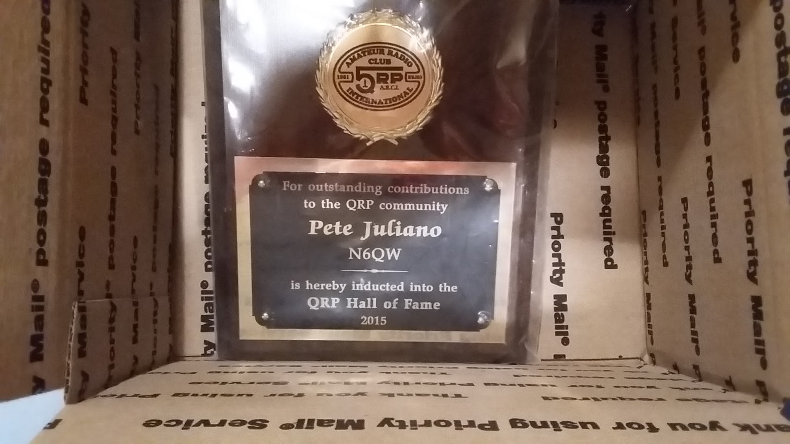
We’ve got a problem: Pete Juliano and the QRP Hall of Fame 🙁 PLEASE HELP!
BENCH REPORTS
Pete Releases Smoke (wiring harness)
Pete’s DifX on 60
Architecture and Dual Conversion (uBITX: uses ALL THREE clocks on the Si5351)
The Big Kahuna
ON HACKADAY with Philco SB100 SEE! QRP!!!!!
BITX60
Cap Stack Hack mod (with leads)
Let the smoke out of an Si5351 (shorted output) Several actually.
(Same day delivery zone for Amazon — but no drones or parachutes yet.)
Installed scanning switch
Observations on 60. All the weird bands have a 6 in them: 160, 60, 6
The good: 100 watt limit, wire antennas
The bad: Kind of cliquish– like 75, not much of a CQ band. Channels. Not much activity.
The bad: Kind of cliquish– like 75, not much of a CQ band. Channels. Not much activity.
Met Josh KE8CPD on 40. BITX 40!
TRIBAL KNOWLEDGE:
Socketry: How to keep BNC jacks from spinning loose?
Do you heat shrink?
Feel Tech Sig Gen might not have blocking cap at the output.
Speaking of which, when I spoke of the Ne602, I mostly meant blocking caps, not bypass caps.
How come they don’t have a cable TV channel devoted to radios? They have HGTV? Why not HBTV?
REPORT FROM WINTERFEST
Bad weather. Tailgaters wimped out!
Combined forces with Armand WA1UQO.
Met up with Charles AI4OT.
Acquisitions: 1/4 phono jacks, carbon mic, vero board, disc caps, weather radio,
LARGE collection of Electric Radios from Armand. Wow.
Electric Radio notes: 1st Fifty Years of Sideband 1991 articles by Jim Musgrove K5BZH
Why LSB on 75? — so AMers couldn’t follow to top of band
W2, W6, W8s liked phasing, W3, W4, W0 more into filter rigs.
Early SSB guys turning on carrier and talking AM hams into SSB RX.
Kelvinator Refrigerator rigs.
A reading on the homebrewing of SSB rigs.
Tony Fishpool on QSO Today! Pete mentioned prominently.
Good Hacks from ND6T on BITXHacks, Stockton Bridge
MAILBAG
Farhan’s NEW uBITX Multiband Transceiver (video)
It is, truly, a thing of beauty.
Farhan will be posting details on his web site soon.
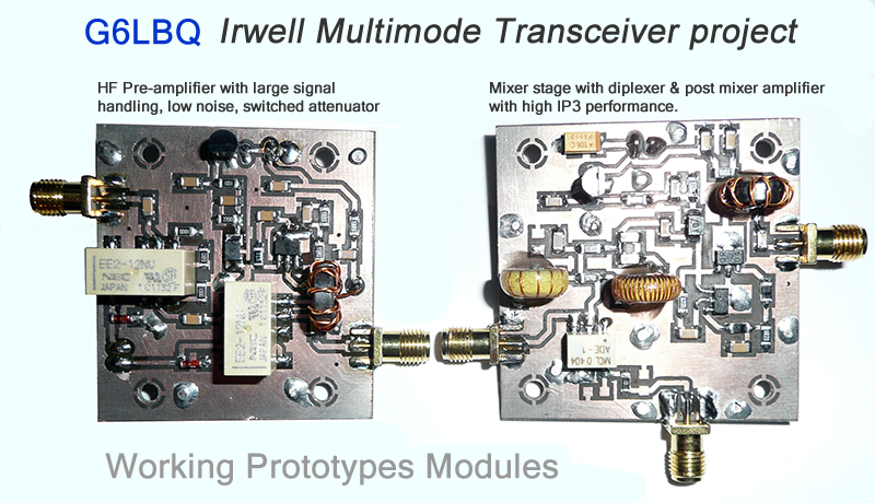
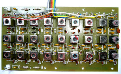
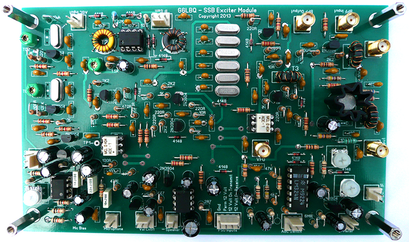
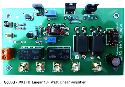
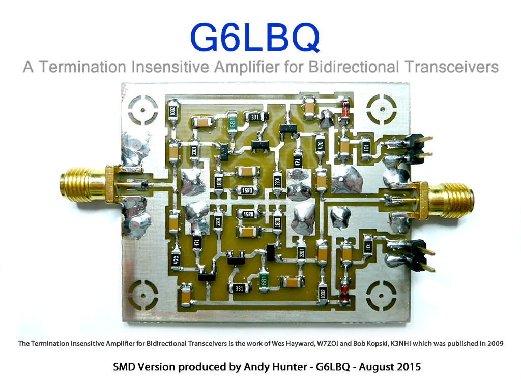
CONFIRMED: Andy G6LBQ Has The Knack (and OTD)
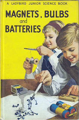
The early fascination with small light bulbs, switches, and batteries confirms the diagnosis. The Ladybird group seems to have led many a young British person down the path to OTD (see the web site for more info on this malady).
https://g6lbq.blogspot.com/
Andy writes:
Hi Bill
I have built a few BitX transceivers and developed a 9 band version which has been built by various hams around the world.
Always look forward to the SolderSmoke podcast which I enjoy immensely.
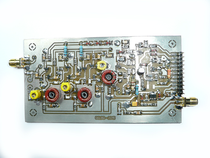
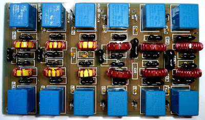
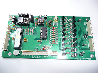
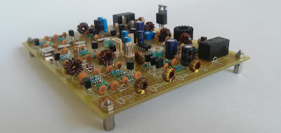
For your interest I have attached some pictures to show you some of the modules I have designed/developed and built for my Multi-Band projects. The SMD boards are for my latest project which I call the Irwell Transceiver, my intention is to make it all band HF and multimode.
Hopefully my pictures will meet with the SolderSmoke approval and the inauguration can take place for recognition that I officially have The Knack, failing this it will be a Basta moment at the G6LBQ workshop!
Keep up the great work you do with SolderSmoke which brings pleasure, fun and inspiration to hams all over the world.
Kind Regards
Andy de G6LBQ

HB2HB: N6ORS, W0PWE (and me!)
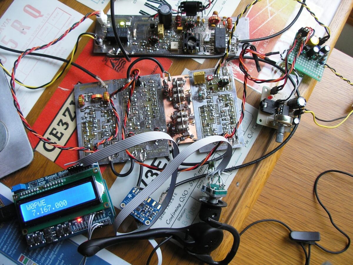
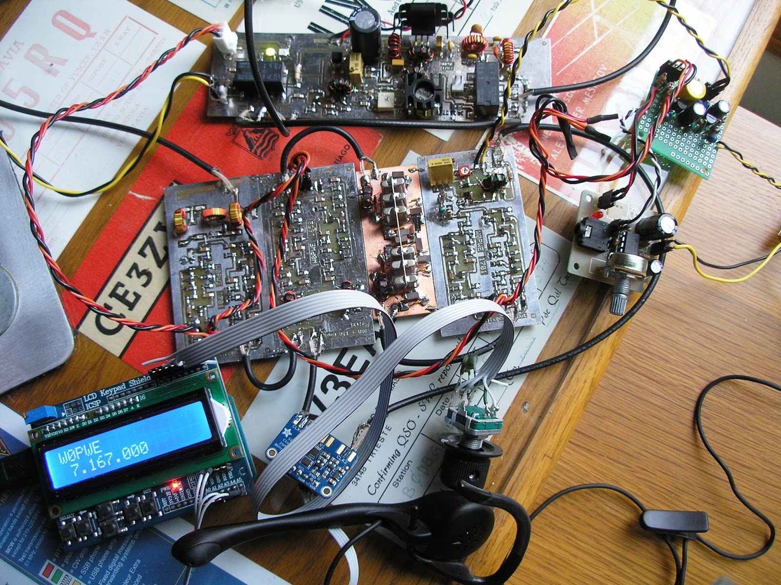
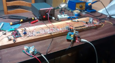
This is so cool. Jerry W0PWE has built a magnificent BITX. With a digital VFO and Termination Insensitive Amplifiers, I think it qualifies as BITX DIGI-TIA #2. Running it “al fresco” he was tuning around on 40 and he heard DIGI-TIA #1 (mine!). As soon as he finished soldering in the power amplifier, he put it on the air and, in his second contact, worked Keith N6ORS — Keith was running his MIN-X rig. Clearly TRGHS. Great work Jerry!
Hello Bill,
Jerry here W0PWE in Iowa. I save up your podcasts and listen to them when I travel. A year or two ago you and Pete got me interested in the BitX and I finally took action. I have plenty of other
projects I should finish but boy was it ever fun to start a new one. This morning I soldered the
last part in my newly hatched Bitx, drug it over to the operating position and had two great QSOs
with it. See attached photo shows the rig as it was during those QSOs.
projects I should finish but boy was it ever fun to start a new one. This morning I soldered the
last part in my newly hatched Bitx, drug it over to the operating position and had two great QSOs
with it. See attached photo shows the rig as it was during those QSOs.
When I finished my first QSO with W9SX, Keith in WI N6ORS called me. He was running a multi-band Bitx he had built and we had a great HB2HB qso. Awesome!
My rig is scratch built, mostly SMT and generally follows the 40M schematic that Farhan has on
his HFsignals page. I am using the Kopski/Hayward TIAs though and I designed a 6 pole crystal
filter for it since 6 of the 10 crystals I bought were very similar when I characterized them
with my PHSNA setup. It uses the Adafruit SI5351 board and I modified a sketch that LA3PNA wrote for the Arduino.
I designed and fabricated the boards for it using the software and process described by K7QO and
W5DOR. Toner transfer with the Hammerhill Gloss paper is working great. The heatsink on my IRF510 is a little light. I could smell the MOSFET warming up during a few of my lengthy transmissions with Keith.
Now the SWL report. While listening on the receiver portion of my Bitx last week I heard you on
7260 at about 0030Z. I think that was Tuesday or Wednesday. I wished I could give you a call but
at that point my PA was merely a few traces on the computer screen. Hope to hear you again on
40M.
73/72,
Jerry – W0PWE
AB1YK’s FB “Al Fresco” Scratch-Built BITX 20
Mike AB1YK built this very nice BITX20. On a board, al fresco. Very nice. He provides a good write up here:
http://n1fd.org/2017/01/18/first-homebrew-contact-on-my-scratch-built-bitx-20-ssb-transceiver/
I feel obligated to defend his poor analog VFO. Mike — that oscillator never had a chance OM! You need to nail that coil and that capacitor down! You threw in the towel and went over to the dark side way too fast. Go back and get that VFO stable.
Similarly, I’d say it is time to put away the keyboard and get out the microphone. This is a 20 meter phone rig after all. Allow it to send your dulcet tones across the seas!
But seriously, great job Mike. There are very few scratch-built homebrew SSB rigs on the air these days. Congratulations OM.
Great Interview with Farhan Re BITX 40 and BITX History
W5KUB has a really good interview with Farhan. There are several spots where the Skype connection gets quite choppy, but hang in there — it gets better. Farhan provides a lot of good info on the history of the BITX rigs, his design philosophy, and the importance of the EMRFD book. He also talks about how the BITX 40 Module is produced. And he talks a bit about possible future rigs. Great stuff.
I was very pleased to hear that Farhan is trying to eliminate the need for his FT-817 (he currently needs it for its general coverage receiver) so that he can have a completely homebrew hamshack. FB!
Christmas Present! 4Z1UG’s Interview with Han Summers G0UPL
I found myself almost cheering out loud as I listened to this wonderful interview, especially at the point where Hans lets it be known that he has NO COMMERCIAL HAM GEAR in his shack! Yes! That’s the ticket! You can also hear the story of Hans and Farhan meeting up in Mumbai for dinner. The interview includes discussion of WSPR and QRSS and BITX and crystal ovens and, at the end, a special QSO TODAY overtime session in which Hans describes the little WSPR rigs that fly around the world, carried aloft by half-filled birthday party balloons.
Thanks to Eric 4Z1UG and Hans G0UPL for this very nice Christmas present.
Listen here:
http://www.qsotoday.com/podcasts/g0upl
Reverse Polarity Protection
When I opened the package from India and saw Farhan’s s beautiful board with all those little SMD parts, I immediately worried about frying those parts by accidentally reversing the polarity of the 12 volt DC input. Believe me, this can happen. It is especially likely during the early, enthusiastic testing and experimenting that takes place in the days after the arrival of a new rig. So, my friends: Save yourselves the agony of fried components! Don’t let your BITX 40 Module go up in smoke! Install a simple reverse polarity protection circuit BEFORE you start working with your new board.
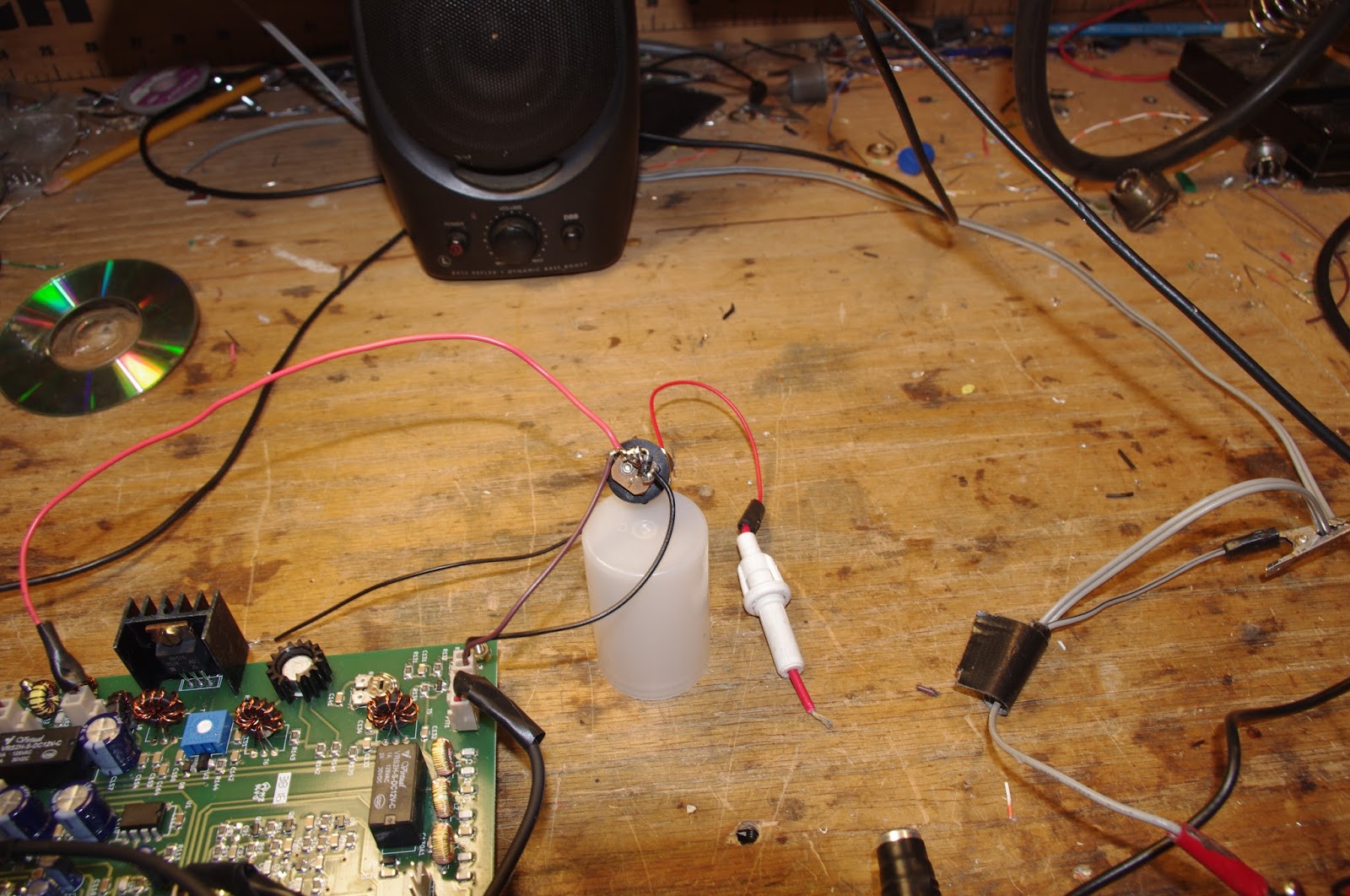
Here is what I did: I just took a diode (a fairly hefty diode) and I soldered it in between the pins of that neat little circular power jack that Farhan sent with the module. Be sure to solder it in so that it does NOT conduct if you have connected the power correctly. The arrow should be pointing to positive terminal. Then put a fuse (3 amp or even a 2 amp) in the line from the connector to the power supply or battery. If you don’t have a holder you can try just soldering the fuse into the line.
With these two little parts, you can save yourself a lot of grief: If (WHEN!) you connect red to black and black to red, that diode will conduct like crazy and will blow the fuse. You’ll just have to replace the fuse (and not the module).
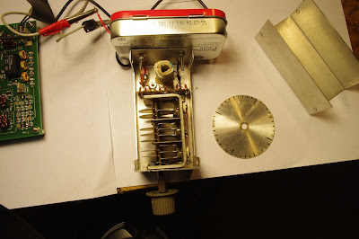
On the Air with the BITX 40 Module
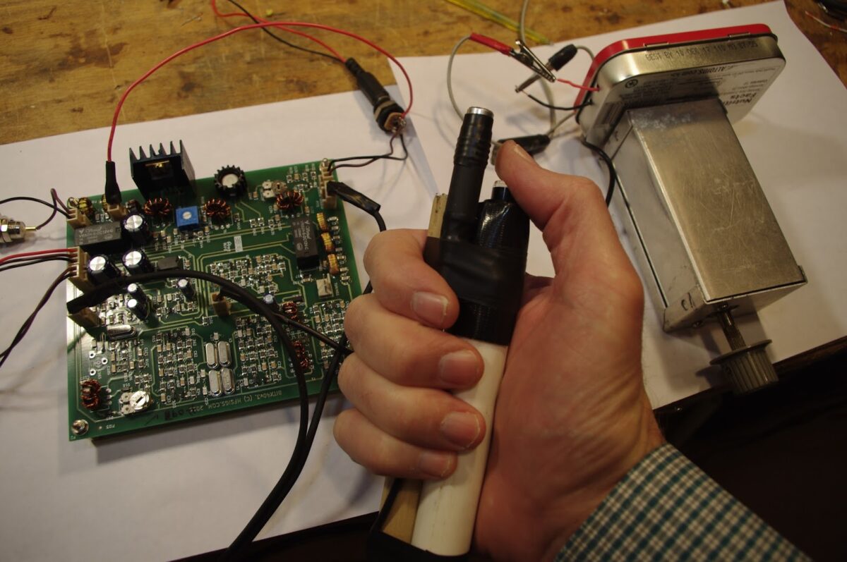

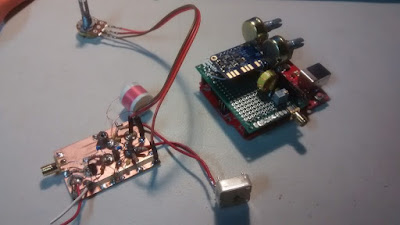
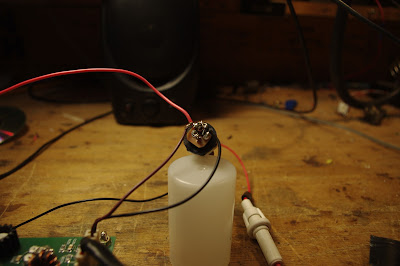
This morning I built a mic/PTT for the BITX 40. I used the little electret element that Farhan sent with the rig. The element sits atop the plastic tube from a pen. For the push-to-talk I used a little push switch that locks down (on) until you push it again (which opens it). This is very convenient — you don’t wear your thumb muscles out on long “old buzzard” transmissions! I used some PVC pipe and some wooden dowel to make the thing a bit ergonomic. It is held together with Gorilla tape.
It works great! I put the rig on the air this morning and very quickly worked KD3TB up in Pennsylvania — Irwin was testing his K3. Then I worked KM4LWP — James was only a mile or so from me, running 3 watts from a KX3. Then Mario, K2ZGW called in. Everyone said the rig sounds great.
In the picture above you see the rig, the mic and (on the right) the VFO.
On the Air with the BITX 40 Module
This morning I built a mic/PTT for the BITX 40. I used the little electret element that Farhan sent with the rig. The element sits atop the plastic tube from a pen. For the push-to-talk I used a little push switch that locks down (on) until you push it again (which opens it). This is very convenient — you don’t wear your thumb muscles out on long “old buzzard” transmissions! I used some PVC pipe and some wooden dowel to make the thing a bit ergonomic. It is held together with Gorilla tape.
It works great! I put the rig on the air this morning and very quickly worked KD3TB up in Pennsylvania — Irwin was testing his K3. Then I worked KM4LWP — James was only a mile or so from me, running 3 watts from a KX3. Then Mario, K2ZGW called in. Everyone said the rig sounds great.
In the picture above you see the rig, the mic and (on the right) the VFO.
Hacking the Hackable BITX 40 Module: VFO is the Way to Go!

I am having a lot of fun with Farhan’s new BITX 40 Module. I think I’m doing exactly what Farhan intended people to do with this rig: work on it, modify it, improve it.
I’ve been working on frequency stability. I was, I admit, skeptical from the start about the stability of a thumb-sized, SMD, varactor-tuned VFO with a ferrite or iron powder toroidal coil. Don’t get me wrong — it worked. But it drifted. It seems to me that it would be asking too much to expect a VFO like this to be drift-free. (But I may be wrong — are there any SMD, varactor-tuned VFOs out there that DON’T drift?)
First I thought it might be the 9 uH metallic core toroid. So I replaced that with a 10uH choke — no ferrite or iron powder in there. That seemed to help a bit, but SSB QSOs would still quickly drift into Donald Duck chatter. Then I thought it might be the varactor diode. I let it warm up. A lot. Still, it drifted. Then I thought it might be the trimmer cap, so I took it off the board. No change. During this process I noticed that even slight pressure on the board caused the rig to shift frequency. I began to suspect that the drift was just structural — a consequence of the physical characteristics of the SMD parts and the board. To get VFOs stable I’ve had to build them big: 10 X 10pf NP0 caps to make one 100 pf cap, large air-core coils, and big sturdy variable caps. I’d isolate the frequency determining elements in a box separate from the powered components. This little VFO just looked too small to be stable.
So faced with drift, at first I asked myself, “What would Pete do?” I took an AD9850/Arduino combination off the shelf and plugged the output into the “DDS” jack Farhan had placed on the board. I removed the 10uH choke. Viola! With the DDS tuned to 4.7 – 5 MHz, the receiver worked great. I briefly tried to updated the Arduino code to take into account the 12 MHz IF (so I could get an accurate frequency readout), but ran into the old painful Arduino IDE problems: Now it is claiming there are library problems. Not wanting to suffer through another round of digi-agony, I left well-enough alone. I used the DDS with the old code for one day.
But of course, I was not satisfied. Attaching a DDS or PLL synthesizer to the BITX 40 Module just didn’t seem right. Heck, it was kind of like just hooking up my FeelTech Chinese sig gen to the DDS jack. Farhan’s rig is simple, beautiful and ANALOG. The parts are small, but you can see them. You can put your scope probe on the collector of Q7 and see what is going on. DDS or PLL. It is a REAL HARDWARE-DEFINED RIG. So I decided to build a VFO. Pete calls VFO’s “grief machines” but for me, the grief machines are those little Arduino beasts. To each his own.
When I build a VFO, I start with the variable capacitor and the reduction drive. I found a nice one (with reduction drive) in my junk box. I tunes from 40 pf to 56 pf. I decided to use the super-simple Hartley circuit presented by Wes Hayward W7ZOI in SSDRA (page 34, fig 7).
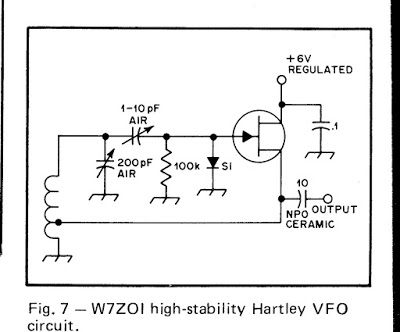
I went with a 4.4 uH air core coil (wound on a cardboard tube from a coat hanger). Consultation with on-line resonant frequency calculators showed that I’d need to put about 180 pf in parallel with the variable cap. For this, I used a bunch (maybe 10?) of small value NP0 caps in parallel. This really helps keep the VFO stable.
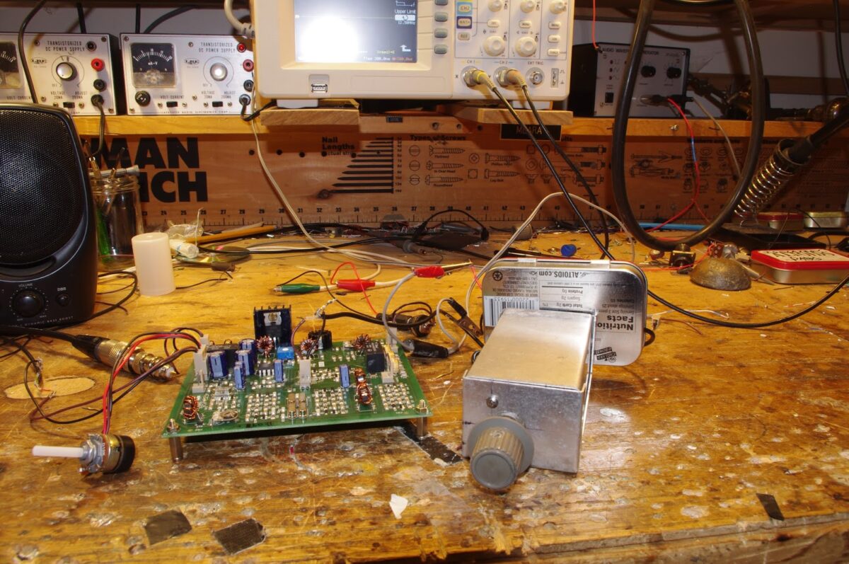
As I did with my HROish receiver, I put the coil and the caps in one box, with the MPF-102 and associated parts in an attached Altoids tin. Everything was glued and bolted down very solidly.
I only built the actual oscillator stage — I decided to use the buffer amps on Farhan’s board.
The oscillator started right up. I had to add and then take away some turns on the coil to get it to run in the desired range. Then I plugged it into the DDS jack — the receiver was working immediately.
I noticed, however, that it seemed a bit less sensitive than it had been with the AD9850 DDS. And when I grabbed the wire going into the DDS connector, audio output jumped dramatically. It took me a few minutes to figure that out: I think the output from my VFO was not adequately turning on the diodes in the diode ring. When I grabbed the wire, I was putting a lot of noise into the mixer port, probably turning the diodes more fully on (but also letting a lot of noise through).
Fixing this problem part was fun: Looking at the BITX 40 schematic, I saw that the two 1000pf feedback caps in the original oscillator were still in the circuit. I figured those caps would be sending a lot of my VFO energy to ground. So I fired up my hot air rework station and deftly removed C91, the 1000 pf cap that is connected to the base of Q9. Instantly the receiver started inhaling as it had with the DDS VFO. That was a very satisfying fix.
This whole VFO project was very satisfying. It was all done in one day, and all the parts came out of my junk box. I think I ended up with an LO frequency source that matches up in a pleasing way with the analog circuitry in Farhan’s rig. And here is bonus that I think is just what Farhan had in mind: this kind of circuit adds a definite homebrew element to the module rig.
I found that this external VFO improved stability significantly. I don’t know if it is as stable as the DDS, but with the external VFO the receiver no longer drifts away as I listen to SSB signals.
Farhan on What’s New in the BITX 40 Module
Writing to the BITX e-mail group, Farhan provides some very interesting information on the philosophy behind his new BITX 40 module, and on how it differs from earlier BITX designs:
The new builders are often caught in a catch-22 : to get on air they need to build a rig from scratch. but to build a rig, they need lots of experience. A way out was to provide working boards where we can get on air quickly, and then start improving and modding the circuit. this is the spirit behind the new boards. Consider them like you would consider a raspberry pi or an arduino : simple, working circuits around which you can grow your own radio.
In the new bitx boards, I have tried to keep as close to the original bitx as I could. however, there are a few departures that I thought the bitx builders here would like to know about.
i have to admit though, strangely, i am less familiar here with bitx than many others on this form. arv, leonard, dan, andy and others have build far many more version than I did. I just happen to be the first one to build a bitx. this as much an acknowledgement of their inputs. without all you folks, bitx would not have had the kind of traction that it now enjoys. I suspect that it is the most built transceiver in the world.
So, here are the changes from the original bitx.
1. SMD
The SMD components make for virtually error free boards assembly. We used the biggest sized SMD components. In fact, the resistors and capacitors are about the same size as a quarter watt resistor that is soldered standing up. They are very easy to desolder without messing around with the desoldering wick and solder pumps. All you do is to lay the soldering iron’s bit on the component such that the flat end touches both sides at once and after a few seconds just drag the component away. I soldered the sample boards with my regular, 2 dollar, 25 watts iron without using a magnifier (I wear reading glasses).
1. 40 Meters
It is just that with the sunspots fading away, 20 meters in the tropics is far less active than before. Many of the us South Indian hams hang out on the lower end of 40 meters every morning and evening. Hence, the choice. That doesn’t mean that i can’t be converted to 20m! There are several ways to change to 20 meters. Keeping the VFO same, change the crystals (and hence the IF) to 8.833 MHz and rework the band pass and the low pass filters. I will work out the details in a few weeks and post them here.
2. A new bandpass filter
The original bandpass filter was quite lossy. I didn’t know how to use any CAD tools when i sketched it. I was actually on a long haul flight when I designed that filter. The new filter configuration is very interesting one. I saw it on PA3AKE’s site. This is a triple tuned circuit with very good out of band attenuation while maintaining very low loss.
In the last then years, ecomm has made it possible for us to globally access good quality toroids anywhere in the world. Hence, we have used T30-6 toroids with excellent low loss. I measured it at just 2 db, the original had more than 6db loss.
3. VCO
The original oscillator on the BITX used a variable capacitor. These were noisy, and often of inferior quality. In any case, they are no longer available. Instead, we have used a varactor diode for tuning. The greater benefit of using a varactor to tune the oscillator is that the tuning control only carries a DC voltage. You can install it anywhere. If you need finer tuning control, you can add a second lower value tuning pot in series with the main tuning pot. It is easier to add FLL to a VCO.
4. Audio muting
The original BITX used just a switch to move from receive to transmit. The receive voltage charged receiver’s audio preamp’s decoupling capacitor and it took time to discharge. this kept the audio preamp active even on transmit and caused a very sharp audio noise on the transmit change over. Now, the other section of the T/R relay is used to cut the audio off to the LM386 as soon as transmit line is energized.
5. A better T/R system
The original bitx didn’t have a PTT. this one has two relays to switch the linear amplification chain in and out of the circuit, mute the audio and change over the antenna. These changes lead to a very stable linear amplifier and smoother change over.
6. Mic amplifier
The original mic amplifier easily saturated. The new design, thanks to dan tayloe, has a better head room and provides very clean modulation.
7. The fixed BFO
Though the PCB has the provision for a trimmer and an inductor to pull the crystal frequency. I discovered that with five matched crystals, if you used 4 in the ladder filter, the fifth’s frequency fell right into the perfect sweet spot for LSB work. You might need to add the trimmer and an inductor back for USB work.
8. DDS connector
To use the DDS, you will have to remove L4 (the VFO inductor) and inject the DDS/PLL output into the connector provided.
There are some smaller mods that people can try out:
* The current in the receive amplifiers can be reduced if you don’t have any radio hams in your neighbourhood who run kilowatt amps.
* The capacitor between pins 1 and 8 of the LM386 can be removed if you prefer headphones to speakers.
Video of BITX 40 Module in receive mode
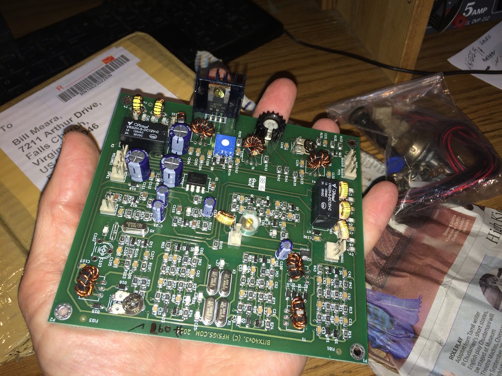
A Package from Hyderabad: Farhan’s BITX 40 Module Arrives in Virginia

I am having a really EXCELLENT radio morning here at SolderSmoke East coast HQ. I made some progress on the Armand HRO receiver — just squaring away some of the too-long leads and improving the shielding a bit. Then I was looking out the window as the mailman arrived. What was that little box he was leaving us? Wow! A box from Hyderabad! The BITX 40 module arrived, wrapped in a very interesting piece of Hyderabad newspaper. Very FB. Thanks Farhan. I will surely be writing and talking about this rig in the weeks to come.
UPDATE: I just realized that the BITX module fits very nicely into a TenTec TPC-45 cabinet that Armand gave me a while back. TRGHS.
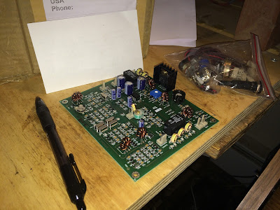
Update on Farhan’s BITX 40 Module
It is truly a thing of beauty: http://www.hfsigs.com/
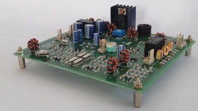
The boards come assembled (as seen above). You can then add peripherals and modify away. It is “hackable.”
Hackable
The BITX40 will inspire you to experiment. Modify it, mount it, tweak it, change it.
The PCB uses all analog large sized SMD components that are laid out on an easy to understand manner on a double sided board with broad tracks. This can be your main module around which you can start experimenting. There are jump-points from where you can add more modules like the DDS, more bands, better audio amplifier, etc. Imagination is your limit. You can separately increase the power amplifier’s supply voltage to 25 volts to be more than 20 watts of power : You will have to add a better heat sink. The mods are on the way!
The board can be installed inside any box that you like. Make your own station rigs, man-packs, trail radios or mount it in a cigar box and leave it on your bedside table. The tuning capacitor has been replaced by a varactor tuning so you can place the tuning knob anywhere as it only carries a DC voltage.
Farhan writes:
For the last few months we have been working bringing low cost, tested SSB boards. Finally they are here. Priced at Rs.2200 At the moment, they are available only in India until we sort out an inexpensive way to post them to other countries. Visit www.hfsigs.com and pick up one!
The BITX40v3 is a complete 7 MHz SSB transceiver on a board that puts out 5 watts of clean audio and it has a very crisp, all analog receiver. It is based on the popular BITX circuit. It is a high quality double side, PTH PCBs with machine assembled SMD components, hand wound coils and each of them is individually tested. All the connectors and wires needed are included in the kit.
The BITX40v3 is a complete 7 MHz SSB transceiver on a board that puts out 5 watts of clean audio and it has a very crisp, all analog receiver. It is based on the popular BITX circuit. It is a high quality double side, PTH PCBs with machine assembled SMD components, hand wound coils and each of them is individually tested. All the connectors and wires needed are included in the kit.
Update on Farhan’s BITX 40 Module
It is truly a thing of beauty: http://www.hfsigs.com/
The boards come assembled (as seen above). You can then add peripherals and modify away. It is “hackable.”
Hackable
The BITX40 will inspire you to experiment. Modify it, mount it, tweak it, change it.
The PCB uses all analog large sized SMD components that are laid out on an easy to understand manner on a double sided board with broad tracks. This can be your main module around which you can start experimenting. There are jump-points from where you can add more modules like the DDS, more bands, better audio amplifier, etc. Imagination is your limit. You can separately increase the power amplifier’s supply voltage to 25 volts to be more than 20 watts of power : You will have to add a better heat sink. The mods are on the way!
The board can be installed inside any box that you like. Make your own station rigs, man-packs, trail radios or mount it in a cigar box and leave it on your bedside table. The tuning capacitor has been replaced by a varactor tuning so you can place the tuning knob anywhere as it only carries a DC voltage.
Farhan writes:
For the last few months we have been working bringing low cost, tested SSB boards. Finally they are here. Priced at Rs.2200 At the moment, they are available only in India until we sort out an inexpensive way to post them to other countries. Visit www.hfsigs.com and pick up one!
The BITX40v3 is a complete 7 MHz SSB transceiver on a board that puts out 5 watts of clean audio and it has a very crisp, all analog receiver. It is based on the popular BITX circuit. It is a high quality double side, PTH PCBs with machine assembled SMD components, hand wound coils and each of them is individually tested. All the connectors and wires needed are included in the kit.
The BITX40v3 is a complete 7 MHz SSB transceiver on a board that puts out 5 watts of clean audio and it has a very crisp, all analog receiver. It is based on the popular BITX circuit. It is a high quality double side, PTH PCBs with machine assembled SMD components, hand wound coils and each of them is individually tested. All the connectors and wires needed are included in the kit.
HB2HB QSO with N6ORS — MIN-X to BITX
That’s Keith N6ORS’s MIN-X transceiver. Keith explains that it has circuitry from the BITX, the Minima and even from the ZL2BMI DSB rig. We featured the MIN-X before, when it was still outside the box:
http://soldersmoke.blogspot.com/2016/01/n6orss-min-x-crosses-pond-on-first.html
I was on twenty today with my BITX, finishing up a rather disheartening contact with a fellow who told me that he is a “checkbook operator.” I was trying to encourage this fellow to build something simple — perhaps a Michigan Mighty Mite? He told me that he might give it a try, but only 16 years from now, after he retires. It was like a case of the Anti-Knack! Then Keith N6ORS saved the day by calling in with his beautiful MIN-X HOMEBREW transceiver. We had a nice talk — Keith mentioned the beauty of Pete’s “Blue Rig.” That’s HB2HB (phone) QSO #5 for me. Thanks Keith!
Bill,
That was great fun!
I was just tuning around and heard you mentioned the Michigan Mighty Mite
so I stopped to listen and realized it was you!
Well here was my chance for a homebrew to homebrew with ‘the man’ himself.
I wanted to record it but missed the chance.
Here is the Min-x boxed up. the case is made from thrown away computer cases.
It runs about 70watts on 160,80 and 40 meters and about 35watts on 20 meters.
I promise to write it up, maybe even draw a schematic. hihi.
73,
Keith N6ORS
Here’ a short clip of the MINX in action:
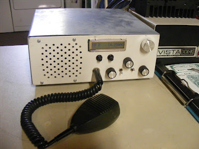
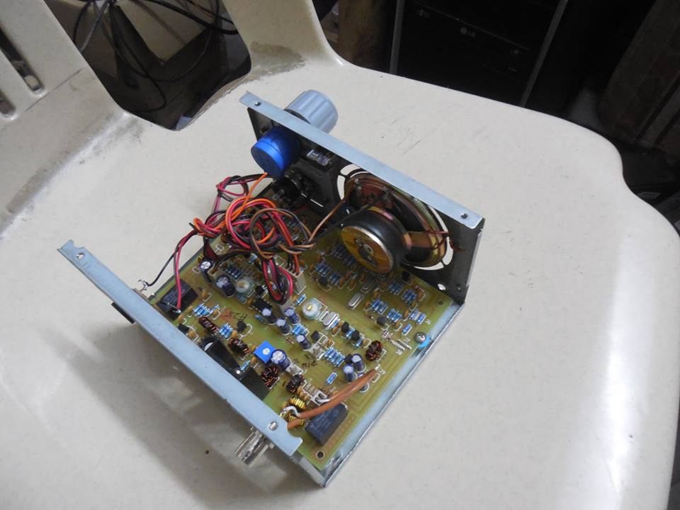
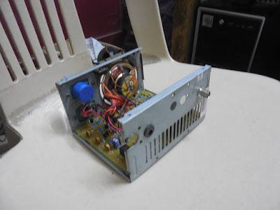
Re-purposed Computer Power Supply Box Provides a Home for a BITX Transceiver
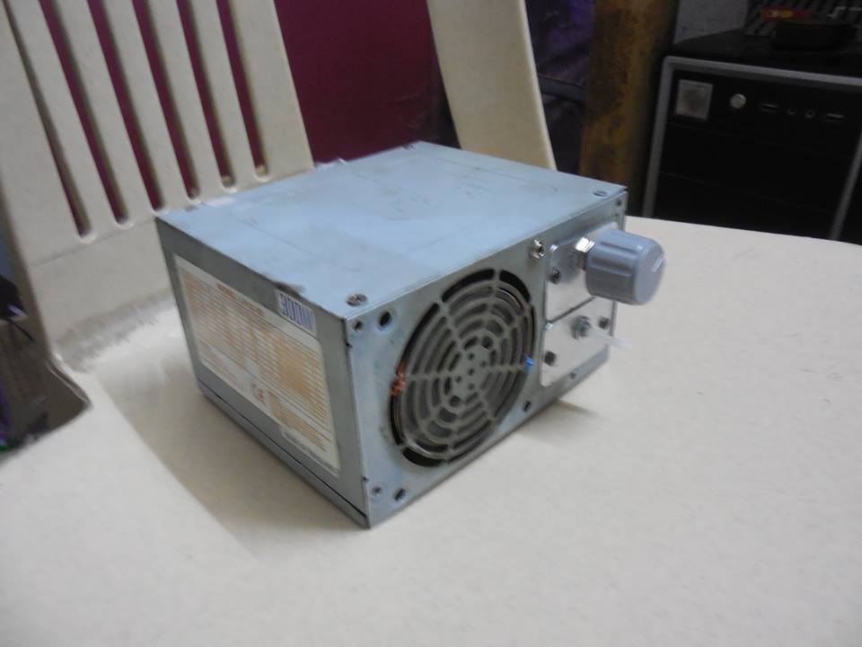
Jaydip VU3JOJ came up with a really inventive way to box up his new BITX transceiver. Nicely done. I especially like the way he put the speaker in the space intended for the fan. Very nice.
This appears to be one of the new BITX 40 meter “modules” described in yesterday’s blog post. FB! How fortunate the new board fits in the power supply boxes. That’s very lucky.
You know, I had an old computer power supply in my hand just yesterday. I almost threw it out. Obviously that would have been a mistake.
Today was a BITX day. Using my BITX DIGI-TIA on 40 I had a long QSO with Rich N3TDE. Rich has a BIT20 built from a Hendricks kit acquired at Dayton. He takes it with him on the Appalachian Trail.
A Really Nice Project: Farhan’s BITX40 Module
Wow, that board is a thing of beauty. And the story behind it is even more beautiful. Our friend Farhan took his famous BITX circuit, shifted it to 40 meters, and put the whole thing on one small board. It is now a module, but a module that makes up an entire SSB transceiver. The idea is that this module can provide a base for expansion and experimentation. You can add a digital display. Or a (gasp!) digital VFO. Or an RF amplifier. Or more bands. Or all of the above. It is a very cool idea.
Here is the most beautiful part: In an effort to help people who need help, Farhan has arranged for a collective of women to assemble the boards in their homes. They needed work, and Farhan gave it to them on good terms. Bravo Farhan!
In keeping with the earliest purpose of the BITX rigs (simple transceiver for Indian radio amateurs) this board is currently only available in India.
Check out the site:
The circuit description is especially good: