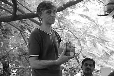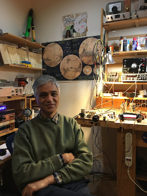
Our good friend Farhan came to Northern Virginia last week for the 50th Anniversary Symposium of AMSAT. We were really delighted that he also came to SolderSmoke HQ. Elisa and I gave him a lightning tour of Washington DC (including a quick visit to The Air and Space museum) and then we headed back to the shack from some radio work.
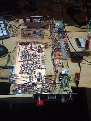
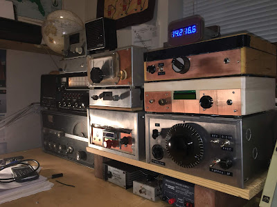
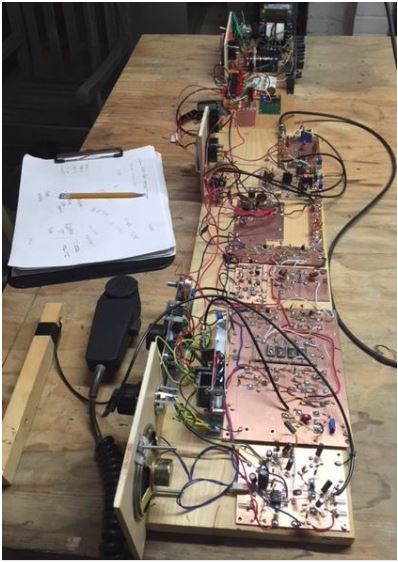
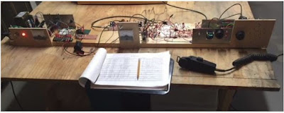
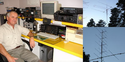
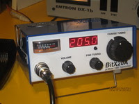
In the picture above you can see my BITX-20 (that Farhan designed) off his right shoulder. Off his left shoulder you sits my ET-2 rig. I really wanted to show Farhan how well the N0WVA regen performs — he was impressed, especially when we started listening to SSB contacts. It was really amazing that we were doing this with just one J-310 FET. This was great fun. Farhan tells me that he will soon take up the “two transistor challenge.”
When he was here in 2017, I tried to demonstrate my version of Rick Campbell’s R2 Direct Conversion receiver. Unfortunately, when I tried to show off the “single signal” capability that is the whole purpose for this receiver, it was NOT producing a single signal output — you could hear the signal on both sides of zero beat. One of the small AF chokes I had used had gone open, knocking our one of the two DC receivers. This time I had the problem fixed and single signal reception was successfully demonstrated.
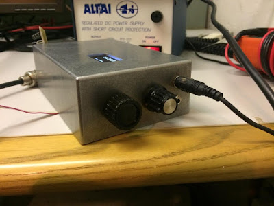
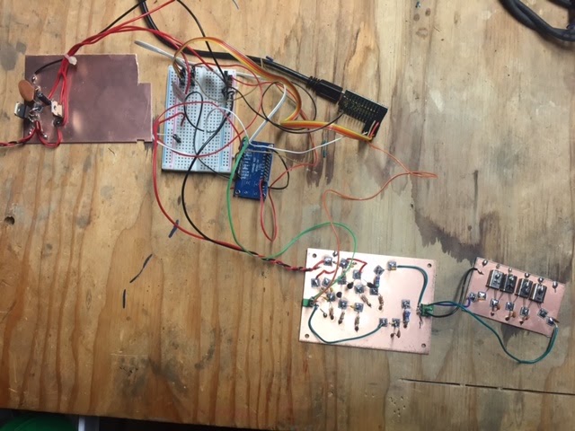
Farhan brought me two pieces of test gear that I have needed for a long time: A step attenuator and a two tone generator. Paired with his Antuino, these devices will bring about a big increase in capability on my bench.
It was really great to have Farhan in the shack. We had a great time talking about ham radio and homebrewing. Elisa and I both really enjoyed hearing from Farhan about his travels and about his life in India. We are all really lucky to be in the same hobby as Ashhar Farhan. Thanks for the visit Farhan.
Here is a quick video of Farhan tuning the BITX 20.