Thanks to Peter VK2EMU for alerting us to this important birthday.

SolderSmoke Daily News — Ham Radio Blog
Serving the worldwide community of radio-electronic homebrewers. Providing blog support to the SolderSmoke podcast: http://soldersmoke.com
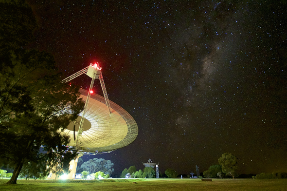
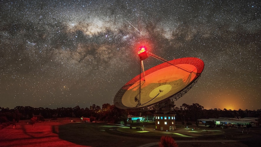
An article about SETI and our favorite dish. From Scientific American:
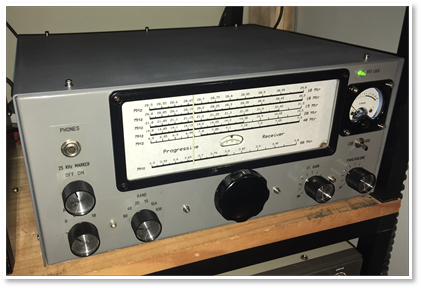
Google led me to VK2FC’s amazing site. I was digging up info on product detectors and I landed on Glen’s description of his version of the W7ZOI Progressive Receiver. Glen’s website provides a very detailed, board-by-board description of how to build this great receiver. I now want to build one.
http://www.vk2fc.com/progressive_receiver.php
Glen’s site has many other projects. Check them out:
http://www.vk2fc.com/index.php
And here he is, the Wizard of Horseshoe Bend:
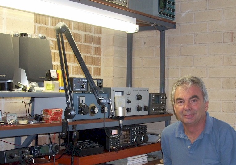
As young James Clerk Maxwell used to say, “What’s the go of it?” and “What’s the particular go of it?”
I studied this circuit carefully when I was using it as a balanced modulator in my DSB rigs. I wrote up my conclusions in my book “SolderSmoke — Global Adventures in Wireless Electronics.”
BALANCED MODULATOR CONFIGURATION:
When I was using it as a balanced modulator, I had the RF “carrier” signal going into L1. This RF signal was 7 dbm, enough to switch the diodes on at voltage peaks. With the “center tap” of L2/L3 grounded for RF, this meant that when the “top” of L2 is negative, the “bottom” of L3 is positive. In this situation BOTH D1 and D2 will turn on and conduct.
When the top of L2 is positive, the bottom of L3 is negative and neither of the diodes is on. Neither conducts.
So we have the RF signal turning the diodes on and off at the frequency of the RF signal.
Audio from the microphone and mic amplifier is sent into the center tap connecting L2 and L3. The level of this audio is kept low, below the point where is could turn on the diodes. The center tap IS grounded for RF by the .1uF capacitor, but it is NOT grounded for AF. That is key to understanding this circuit.
In essence by turning the two diodes on and off at the rate of the RF signal, the audio signal is facing severe non-linearity through the diodes. We could say it is alternately being multiplied by 1 and 0. This non-linearity is what is required for mixing. We therefor get sum and difference products: Sidebands. At this point, Double Sideband.
The way the transformer is set up means the RF carrier signal is balanced out: Even when the two diodes conduct, the top of R1 and the bottom of R2 are of equal and opposite polarity, so there is no carrier signal at the junction of R1 and R2 (they are actually a 100 ohm variable resistor that can be adjusted to make SURE they balance out). So the carrier is suppressed and all that remains are the sidebands: Suppressed Carrier Double Sideband.
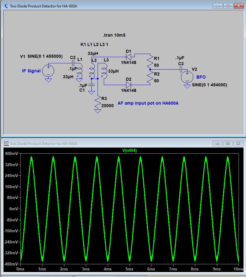
PRODUCT DETECTOR CONFIGURATION:
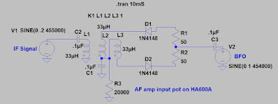
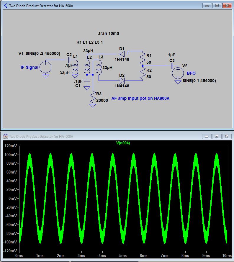
What happens when we use this circuit as a product detector in a receiver? Let’s assume we are working with a 455 kc IF. If you run a 454 kc 7 dbm BFO signal into L1, it will turn the diodes on and off as described above. But you will NOT be able to put the 455 kc IF signal into the center tap of L2/L3 — that center tap is GROUNDED for 455 kc. So you will have to run your IF signal into the resistors, and take the audio output from the center tap of L2/L3. This works. I tried it in my HA-600A. But there is a problem: Envelope detection.
In this arrangement, we are balancing out NOT the 455 kc IF signal, but instead we are balancing out the BFO. We don’t really NEED to balance out the BFO — it can easily be knocked down in the audio amplifiers, and IT is not responsible for the problematic envelope detection. We DO need to balance out the IF signal, because if that gets through we can get simultaneous “envelope detection” and product detection. And believe me, that does not sound good.
So I tried putting the IF signal into L1, and the BFO signal into the resistors (as shown above). I took the audio from the junction of L2/L3. This seemed work better, with envelope detection greatly reduced.
BUT WHAT’S THE GO OF IT?
But how is this circuit mixing in this configuration? The strong BFO signal is still controlling the diodes, BUT, with the BFO signal coming in through the resistors, when the top of R1 is positive the bottom of R2 is ALSO positive. In this situation D1 will conduct but D2 will not. The IF signal is facing a big non-linearity. This will result in sum and difference frequencies. The difference frequency will be audio. But with D1 and D2 turning on and off in a very different way than we saw in the balanced modulator, how does the mixing happen?
I think the answer comes from the summer 1999 issue of SPRAT, the amazing journal of the G-QRP club. Leon Williams, VK2DOB wrote an article entitled “CMOS Mixer Experiments.”
Here is Leon’s 74HC4066 circuit:
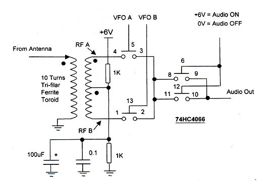
I think those two gates (3,4,5 and 1,2, 13) are the functional equivalent equivalent of the two diodes in our product detector. In Leon’s scheme the VFO is supplying signals of opposite polarity. Ours is providing only one signal, but the fact that the diodes are reversed means that they act just like the gates in Leon’s circuit. The transformer is almost identical to the one we use in the product detector.
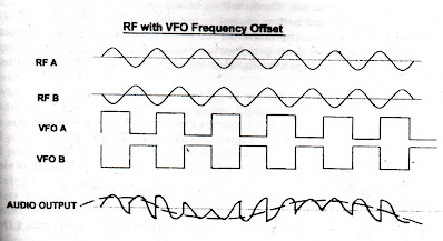
Let’s look at the output from Leon’s circuit:
Paul Taylor VK3HN has really outdone himself in this video (above) and blog post. He describes coming across a somewhat mysterious homebrew SSB exciter with some cryptic markings on it. Paul eventually figures them out. We still don’t know who the builder VK3WAC was — can anyone find him in their logbooks?
As Paul goes through the description of the transceiver he built around the mystery exciter, he mentions a number of hombew heroes including Farhan VU2ESE, Peter DK7IH, Eamon EI9GQ (I have to get his book!), and Don W6JL. Also, our beloved SSDRA book plays a prominent role in the story.
Paul’s video is really beautiful — at one point the camera pans the landscape and we see kangaroos in the field. It is also refreshing — as we suffer in the heat of the northern hemisphere summer — to see Paul and his friends out on the summits in their winter coats and hats.
It looks to me as if Paul built this rig during the current emergency, so I will list it as a Quarantine rig. Every dark cloud has a silver lining, and Paul’s rig has added a bit of silver to the dark COVID cloud. Thanks Paul.
https://vk3hn.wordpress.com/2020/07/26/something-old-something-new-a-four-band-5w-50w-ssb-cw-transceiver-summit-prowler-7/
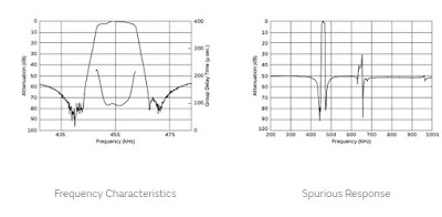
 |
| +/-6kc filter upper left, 455B wide filter to the lover right. |
 |
| Q-31 with can for first IF amps and filters open |
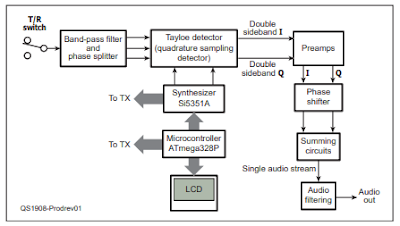
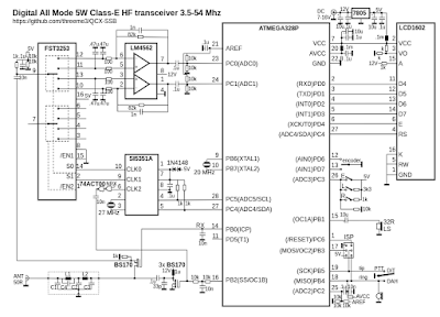
Hack-A-Day carried a very nice video describing recent efforts to turn Hans Summers’ amazing QCX CW monoband transceiver into a multi-mode, multi-mode (including SSB) rig (see above). This is project will greatly interest QCX and SDR fans.
But I wondered how much of the old QCX is still there after the modification. Not much, it turns out.
Here is the bloc diagram of the QCX. It is essentially a phasing rig, using the same principles as my venerable HT-37 transmitter and my version of KK7B’s R2 receiver:
https://nightskyinfocus.com/2020/05/18/diy-satellite-tracker/
DU1AU is way ahead of where I was when I was working with Low Earth Orbit satellites. I just aimed the antenna about 45 degrees up from the horizon, and spun it around with a TV rotator with me –not the computer — as the controllers of the rotator. In essence I did the AZ manually and completely ignored the EL. This design moves the antenna in Azimuth and Elevation, and has the computer control the movements via an Arduino. FB.
DU1AU points to the work of VK3FOWL and VK3YSP. Their site has very detailed info on how to build several versions of this kind of Az-El rotator:
https://www.sarcnet.org/rotator-mk1.html
This Az-El project represents a great opportunity to move beyond hand-held satellite antennas, and beyond my Az-only manual approach. It also give us a way to bring some real homebrewing into a part of ham radio that has come to be dominated by commercial equipment. There are some Arduinos and some lines of code, some motors and some metal work. Great stuff!
I think we should start calling these “Quarantine Rigs.” Many of us are pulling off the shelves rigs that we started a while back but then put aside. Now, with the pandemic, we have the time (and the need!) to work on them.
I like Peter’s BITX receiver video, especially the part in the beginning where he wipes the grime and oxidation off the long-neglected copper-clad board.
Follow Peter’s lead: Pull those old projects off the shelf. Get them going. Now is the time. SITS! Melt solder and flatten the curve.
Thanks Peter.
Nice work Paul.
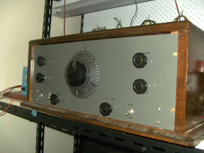
I’m still working on trying to match the excellent results Paul achieved with his AM receiver. Then this morning I wake up to a Hack-A-Day article describing his even more impressive achievement with his AM transmitter.
There was one line from the Hack-A-Day article that made me think of Pete Juliano:
Younger hackers will note the Arduino Nano at the heart of the project, running the VFO and handling all the relevant transmit/receive switching. We can only imagine how welcome modern microcontrollers must have been to old hands at amateur radio, making synthesizing all manner of wild frequencies a cinch.
Indeed.
And once again this story about Paul’s AM operations has made me jealous of the obviously great AM homebrew culture that exists in Australia.
FB Paul!
I’m always delighted when I check the SolderSmoke blog and YouTube list (right hand column of the blog) and find a new post from Paul VK3HN. And this morning’s post is especially good.
Paul has built an AM receiver. Above you can see his video. Here is his blog post with details:
https://vk3hn.wordpress.com/2019/12/06/8-band-superhet-am-receiver/
This is the kind of blog post that makes you want to heat up the soldering iron and start searching through the junk box. I’m thinking about putting Paul’s 6 kHz filter in my 40 meter HRO-ish receiver. And I may make use of his AM detector circuit. And maybe I can put that same receiver on 75 and 160… And then there are the SW broadcast bands… See what I mean?
Thanks Paul. 73
Each November, Peter Parker VK3YE and his ham colleagues from Melbourne share with us reports on Peter’s annual “QRP by the Bay” event.
I think VK3HN should seek a trademark for that hat. As soon as I saw it on the table in the video above, I knew these were Paul Taylor’s rigs. FB Paul. Here is Paul’s report:
https://vk3hn.wordpress.com/2019/11/02/qrp-by-the-bay-chelsea-beach-melbourne-2nd-nov-2019/
Great work guys. Thanks a lot. 73