The Low-Cost, Open Source COVID-19 Ventilator that Farhan is Helping to Build (Video)

While many of us are just trying to pass the time by building Quarantine ham radio rigs, our good friend Farhan VU2ESE has been hard at work on a really serious project: He has been working out how to use an Arduino microcontroller as the electronic core of a simple ventilator that could save thousands of lives in the current crisis. See video above.

Here is background info on the project (from ARRL):

03/23/2020

Amateur radio volunteers from around the world have volunteered to assist University of Florida Professor Sam Lampotang and his engineering team in their quest to rapidly develop an open-source, low-cost patient ventilator that can be built anywhere from such commonly available components as PVC pipe and lawn-sprinkler valves. The amateur radio volunteers are developing Arduino-based control software that will set the respiratory rate and other key parameters in treating critically ill coronavirus victims.
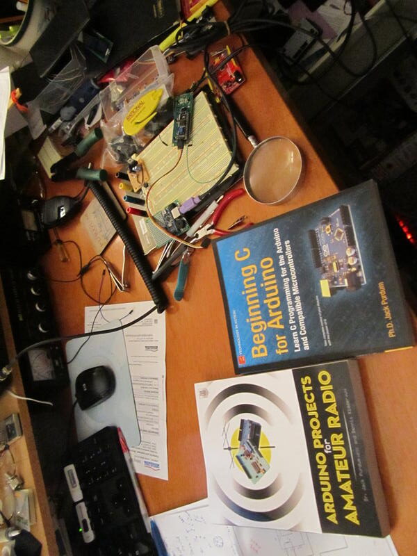
Multiple volunteers responding to a call for help from Gordon Gibby, MD, KX4Z, included noted software developer Jack Purdum, W8TEE, and uBITX transceiver maker Ashhar Farhan, VU2ESE. University of Florida physicians are working to address the critical legal aspects as the design moves closer to fruition.
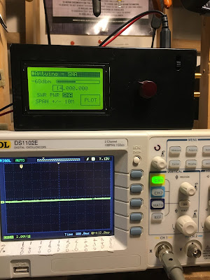
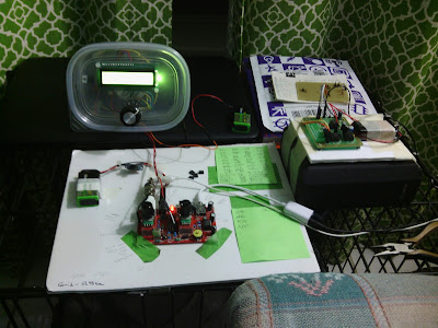
The ventilator’s valves would precisely time compressed oxygen flow into patient breathing circuits under Arduino control, allowing exhausted patients with “stiff” lungs impacted by viral pneumonia to survive until their body can clear the infection. The software design team is also adding simple features such as an LCD display, encoders to choose parameters, and watchdog safety features. — Thanks to Gordon Gibby, KX4Z
It is important realize that in countries around the world, many victims of COVID-19 will have no hope of getting anywhere near the kind of $50,000 ventilators found in U.S. or European hospitals. That is one of the things that makes this low cost, open-source project so important.

More details on the project here:

https://github.com/afarhan/osventproto

Please pass the word on this project. Please forward on Facebook, Re-tweet, etc.

Antuino: Farhan’s Compact RF Lab In-a-Box

I now have Farhan’s latest invention, the Antuino. Pete will have his shortly. Very cool. SWR meter and antenna analyzer, power meter and scalar network analyzer all in one box. I put an old-school knob on the rotary encoder — it seemed like the right thing to do. Soon I will be able to find out if my rigs have spurs or are somehow non-compliant. I’m sure Farhan’s “RF Lab in a box” will be an important addition to my test gear arsenal. We will be talking about this in upcoming podcast episodes.

Mike N2HTT did a nice write up of the new device:

https://n2htt.radio/2019/05/26/hello-antuino/

And here is the info from the htsigs.com page:

http://www.hfsignals.com/index.php/antuino/

Thanks Farhan!

Circuit for Farhan’s Satellite — Arduino in SPACE

Farhan sent me the schematic of the AISAT amateur digital satellite that went into orbit on April 1, 2019 from India. He notes that the circuitry is very simple. Indeed, it reminds me of the very simple but effective circuitry we saw in satellites in the early days of the space age. Beautiful simplicity, with an Arduino on-board. And it is great to see that Farhan did not forget the low pass filter. FB OM.

Pete N6QW Rejuvenates the Atlas Twins with an Arduino and an Si5351

Pete Juliano N6QW has turned his attention to the Atlas Twins, a nice single conversion multiband rig. Pete has used an Arduino/Si5351 to replace the analog oscillators in the old Atlas. This improves stability and allows for USB/LSB operation.

Pete very graciously kept the old analog circuitry in the rig, allowing the Atlas to be returned to its pristine analog state at some time in the future. Pete also made some very kind comments about the surprising stability of the original analog oscillator circuitry.

Check out Pete’ site for more details:

http://n6qw.blogspot.com/2018/11/2018-year-of-ssb-transceivers.html

VU3XVR’s Assembly Language 1K AtTiny-Si5351 VFO

Although Ram VU3XVR’s project is in the digital realm, his barebones approach to the bits and bytes is, for me, very appealing. He takes a Si5351 and runs it with ATtiny13 with only 1k of space. He makes intelligent use of every bit of that space. He reveals his overall approach to rigs when he states in the video that his VFO will NOT have the traditional glowing numeral frequency readout because those bright lights can be so annoying and distracting. I’m with your Ram! Well done OM. Simplicity is a virtue. No more trouble with the Arduino and its fickle IDE. No more agonizing visits to the Si5351 library.

I see lots of applications for this little circuit. Ram mentions beacon transmitters.

He provides details here:

https://vu3xvr.blogspot.com/2018/07/si5351-dds-clock-generator-using.html

INTERVIEW: Bob Crane Talks to Jack Purdum W8TEE at FDIM. Definition of “Homebrew.”

Jack Purdum has been making enormous contributions to the radio art. His background with digital technology has opened many doors for homebrewers, especially through his books on the use of the Arduino microcontroller. I think his new “JackAl board” is really going to shake things up. I was glad that our correspondent in Ohio, Bob Crane W8SX, caught up with Jack and interviewed him for soldersmoke:


But I have one small disagreement with Jack. It has to do with the definition of “homebrew.” Jack seems to define true homebrew as “designing and building your own rig from scratch.” My problem is with the “designing” part. By this definition, those intrepid heroes of days-gone- by who saw a schematic in QST, ripped apart some old broadcast radios, and used the parts to build a 50 watt CW transmitter with a regen receiver were not true homebrewers. I would maintain that they were. I agree with Jack that kit building is a bit different, and of course designing the rig yourself earns you the coveted “designer” designation. But for me, if you start with a schematic and an article, gather the parts and build the thing yourself, that is a homebrew project and you are a homebrewer. After all, even the designers are very often making use of standard blocks of circuitry (Colpitts oscillators, common emitter amplifiers, power supply circuits, etc.)

I think we will have to turn to our lexicon expert Steve Silverman for a ruling.

In any case, thanks to Bob Crane and to Jack Purdum.

KE4MIQ’s Repurposed Raduino Receiver


FB James — Really glad you are listening, and that you are having fun with a Direct Conversion receiver — souped up with a Raduino!


Bill, Pete
Just listened to #204. (New Listener)

You talked about using the Raduino with other radios.

I bought one of Mike Hagen’s RaduinoXs to use with my Bitx40. So, I have repurposed my original Raduino as a VFO for my 4SQRP ZZRX-40 DC receiver. I used Allards’s v1.26 with a few code changes to tune 7.000 to 7.300. It’s currently al fresco on a piece of Hobby Lobby foam board. I may “cabinetize” at some future date.

Attached is a pic of the ZZRX-40, Raduino, and Goodwill Sony speaker with Jameco stereo amp, all running off of Harbor Freight 9v Nimh rechargables.

So far I have heard over 40 states and 20 countries with a 65ft piece of wire in the rafters.

73s

James

KE4MIQ

Yet Another Household Item Useful to Homebrewers: Toilet Bowl Cleaner for PC Board Fabrication

Picture

We have already been using Desitin ointment for heat sink compound, kitchen breadboards for radio breadboards, Scotchbrite pads for polishing, nail polish varnish for toroidal core coating and Olive oil as a field-expedient lubricant. (Am I forgetting anything?) But I must say I was a bit taken aback by KV4QB’s mention of his innovative use of the dilute hydrochloric acid in toilet bowl cleaners in his PC board fabrication process. Good one DuWayne! Eric Guth went the extra mile be suggesting a recycling of the liquid.


This was a really interesting QSO Today interview. Listen here:

Jeff Damm WA7MLH on QSO Today


Happy New Year!

There was so much wisdom and tribal knowledge in Eric Guth’s interview with Jeff Damm WA7MLH. It was almost overwhelming.

You should all listen to it. Twice. At least twice:

https://www.qsotoday.com/podcasts/WA7MLH

My notes:

— I sympathize with Jeff’s decision to go solid state and give up on high voltage after an encounter with an undischarged 600 volt capacitor.
— I really like the 1700 kHz IF with a 5 MHz VFO for an 80 and 40 meter receiver.
— Interesting that EE degree didn’t help much in his efforts to understand ham gear. Better to read Wes’s books and Doug’s.
— Tek Spectrum Analyzers were specially made to fit down a submarine hatch.
— Building and measuring just as important as studying the theory. Inked-up text books.
— Learned ugly from Wes as a teenager.
–Searched for old commercial gear to gut and use as homes for homebrew solid state gear. The enclosures, panels and controls are very useful. Great way to avoid metal work. These rigs are no longer boatanchors! Again, I sympathize. I’ve sacrificed many Heath Lunchboxes and QF-1s.
— Jeff Builds the VFO first. My preference too. But he understands Pete’s AF-first approach.
— Finger on the input of the AF amp! Buzz! Yea! Step your way back to the front end.
— ALWAYS one stage at a time.
— Osh Park Boards for standard circuit modules. Like Legos.
— Cubic Feet of air variables. Jeff has a lifetime stash.
–Thinking about what was and should have been his section of EMRFD. Go for it Jeff. PLEASE!
— Hesistant about chips. Analog guy. Would have been a huge time sink. Analog guy.
— Buying parts on e-bay. Fewer and fewer RF parts at hamfests.
— People reading QST Tech Articles for entertainment. Editor apprach: “Nobody will build it anyway.” Handbooks giving priority to entertainment and less to information and education.


ZL2CTM’s Homebrew Transceiver Project

Wow, Charlie has a lot of very cool ideas in this initial video. Some suggestions:

— With the IRF-510 in the final, beef up the heatsink, and follow Farhan’s lead by including an option for 24 volts on the drain. That would take you up to 20 watts or so (for those who are so inclined).

— Could that Teensy SDR board work at the IF frequency? If so, consider putting it ahead of the crystal filter. This would enable us all to join the Waterfall Signal Purity Police Force.

— I love the OLEDs too, but I found them to be noisy. I minimized the noise with shielding around the OLED and active decoupling on the power line to the AF amplifiers.

More of Charlie’s work here:

https://plus.google.com/107506245856154702088

AC9JQ’s Mini Digi VFO/BFO Al Fresco with OLED (and noise test)

From Dean AC9JQ:

Just completed the VFO/BFO/Arduino/OLED module for my radio. I also have the LPF, BPF and crystal filters completed and tested. Next will be the audio amplifier and NE602 modules. I will probably build one of the NE602 modules and test things out as a DC receiver. My ultimate plan is to have the rig no more that 1″x3.5″x3″. I still have a lot of “stuff” to stuff into that size of box. I’ll keep you posted.


I have been able to contain the entire Arduino/Si5351/OLED into a small cube in the front. The rest of the radio has to fit on two levels in the rest of the area behind the Arduino/Si5351/OLED. I think I will build the audio section and on NE602 mixer and run it as a direct conversion first to vet out any noise or other problems. Bill, that small coax that you pointed out will really help on this build. I used a small piece as a power feed-thru and will use it to feed out the VFO/BFO signals, thanks again for that pointer.

I decided to test for noise on the TIA transceiver test bed. See the video of the results. Not too much noise. I’m only using my indoor magnetic loop for an antenna. Video is kind of sloppy, but taking off the antenna and turning up the volume shows how little noise is left in the system. Now time to stuff the rest of the radio into the tight quarters.


I purchased OLED from ebay…….

They are nice and compact, although as time goes on, I’m sure they will be harder to read. I’m hoping to have an alfresco version in a week or two. I used much of Pete’s code from the shirt pocket transceiver upgrade, modified the code to address the smaller display and add USB/LSB capabilities.

73’s Dean AC9JQ

FDIM: W8SX Interviews W8TEE on Facelifts for SSB Rigs

Our intrepid correspondent Bob Crane interviewed FDIM speaker Jack Purdum W8TEE. Jack made some very intriguing comments on his efforts to enhance the beloved BITX transceiver. CW! AGC! Speech processing! Woo hoo! We await more details on how to acquire the board that Jack describes.

Jack is a very accomplished guy who has made many contributions to the radio art, most recently on Arduino microcontroller projects: https://www.qrz.com/db/W8TEE

Listen to Bob’s interview with Jack here:

http://soldersmoke.com/FDIM17W8TEE.mp3

Thanks Jack! Thanks Bob!

Here are is the manual, bill of materials, and schematic for Jack’s board:

http://soldersmoke.com/W8TEEschematic.pdf

http://soldersmoke.com/W8TEEmanual.doc

http://soldersmoke.com/W8TEEbom.doc

FB IBEW HB DC CW de UAE: A65DC’s International Homebrew Rig

Good evening!


After my JOO moment, Bill put me in contact with Pete Eaton, who suggested that I would have a look at the schematics for K4GC 40m CW Transceiver.
And I did, It was just perfect for me, low part count, lots of things done in software!!! Perfect Bryan!


I started off the build and both Bryan and Pete supported me along the way, thank you!

So here we have it:
The design slowly deviated further and further from the original, but I think I learned quite a lot by starting to make it “my own”.

The Arduino was changed to an UNO, yeah they are clunky and big, but I was not shooting for a pocket-size anyway… and they do have a proper USB port.
The RF-path is now switched by a relay straight after the filter, when the relay is relaxed the antenna is connected to the mixer, when I touch a paddle it connects to the TX circuit.
I have a short hang time from the last key input and it goes back to RX, VOX Delay I guess.

I completed the 700Hz bandpass filter, boy! this makes it a much nicer rig to work CW, I originally I skipped this filter for no good reason? That is the board standing up in the picture.
The TX circuit is a two stage, the first stage is a replica of VK3YE beach40 amplifier circuit, that also uses DB139. The second stage is a spin of the EMRFD Page 2.38 IRF511 Amp.
I have cranked it up to 17w, but it gets too hot too fast, as you can see I don’t have any proper cooling yet, I need to redo this board and plan for the heatsink a bit better.. it is now set around 10w, still getting hot, “599 TU 73”.
To be honest my CW does not go much further anyway, but I guess with this radio now completed I have one more reason to get my speed up.
I use for convenience both CLK0 and CLK1, when I go into TX I switch off CLK0 and do the keying on CLK1, both transmitter stages are powered up the whole time (until I stop keying as described above)

As the 700Hz filter worked so superb, I decided that I wanted to introduce “modes” to the rig, I can now switch the audio either thru the filters (CW) or straight to the AF amp (AM).
I do enjoy listening around, and we have a lot of AM stations on offer in my region.

I kept the smart RX mute transistor circuit and when I ask the Arduino to change mode, it will mute the receiver quickly, pull the relay and then un-mute again, no ear pain from the loud relay click. (I am happy with that detail).
The 2 line display became a four line, and I can change Tuning Rate, RIT, Key Speed and Mode by using only the encoder and the one button built into the encoder.
The front panel sports, on off, Headphones, Paddle and volume, the display and the big knob.
Power connector and USB Port on the side. I did complete the CAT control changes while working on this radio, it now uses the classic Kenwood interface e.g. TS480. (A lot fewer questions from the PC to answer.)

The CAT control works very nice while using N1MM, it works a lot less nice using CQRLog, I guess it has to do with the number of times the software in the PC is asking about things from the radio.
I will look into logic to only worry about incoming serial requests if I have not answered for some time, and never answer while in TX…

By pressing the VFO button a small arrow appears next to TR, if I push again it moves the arrow down to RIT and so on.
if I turn the knob with the arrow standing in front of e.g. KEY it will increase or decrease the KEY speed, when I press again, it will return to frequency control.

Oh, another detail (that I am happy with) while the arrow is in front of the KEY, you can fiddle with the paddle with out transmitting.. practical for testing the speed.

So this is a K4GC transceiver with bits and pieces from VK3YE and bits from the A65DC laboratory in Dubai, truly international.

To trim things in I scheduled a QSO with a local ham here, and things worked very nice, later the same night I made my first “DX” contact with RM2D!!! Moscow!!
What are the odds that a Swedish guy living in the UAE makes the first contact to another Swedish ham who lives in Russia!

73,
Martin A65DC

Channelized! BITX 60 with the Five Channels (with video)

Here’s an update on my BITX 60 project. The modified module is in the lower box. An Arduino Uno and an Si5351 (this one with unreleased smoke) is in the Heath QF-1 box on the top. I am using an Arduino sketch written by Don ND6T. It spits out the needed 17 MHz LO freq needed for each of the five 60 meter channels. You can scroll through the channels by just holding down the rotary switch interrupt button.

There is a move afoot to liberate from channelization about 15 kHz of the 60 meter band. When that happens, I’m ready to go — I’ll just reconnect the rotary encoder for the Si5351 and load some new code. I suspect that by the time that happens, Don will have modified his code so that the 15kHz “tunable” segment will be integrated into the current program and will appear as one of the options as you scroll through the choices.

For reasons that most readers will understand, I have resisted channelization for many years. But here I am, channelized on 60. It is not so bad. I’m having fun listening to a new band, using a modified BITX, an Arduino, a bit of Heathkit and code from a fellow ham.


WA8WDQ Builds OZ1JHM’s Arduino CW Decoder (Video)


Bill, Pete:
I wanted to update you on my DC receiver progress. While I’m still operationally proficient in CW, many of my friends are not. So I thought it would be fun to add a CW decoder to my DC receiver.


In my research for a solution, I ran across a sweet decoder I thought might be of interest to the SolderSmoke listeners. OZ1JHM developed a totally software based decoder for Arduino that uses the Goertzel Algorithm. This algorithm performs similarly to a Fast Fourier Transform but only for tone decoding at specific frequencies. This limitation keeps the code small and fast making it perfect for microcontrollers like the Arduino.

I was able to hack Hjalmar’s code into mine and the result is CW decoder functionality in the receiver with no additional hardware! But, the Arduino Uno’s performance is limited so I need to dynamically switch between receiver VFO/control code and the CW decoder in order to preserve real-time performance. This is only my first pass so perhaps I will find a way to optimize the code to more fully integrate the two. I currently switch back and forth based on whether the VFO knob has been rotated or is idle. This at least gives the illusion of real-time integration but makes it harder to tune in a signal for the decoder.

Now that the Arduino Zero is available, I’ve been considering moving that direction to dramatically improve available horsepower. This isn’t the first time I’ve run out of gas with the Uno. Now it’s time to start working on a transmitter module for the radio :). You know, even though I have an operational K3, I find myself reaching for this radio first. Something magical about using something you’ve created :). But hey, preaching to the choir!
Be sure to check out Hjalmar’s site (http://www.skovholm.com and

http://skovholm.com/cwdecoder) for details on his design and a video demo.

Brad WA8WDQ