

 Steve Smith sent me a good article on broadband transformers. Reading through it, it occurred to me that perhaps using a heavier gauge wire in that PA output transformer might help. So I rebuilt the FT-50-43 transformer and put it in the final. No joy — output was still down around 1 watt. Then I tried adding two turns to the secondary (on his web page Farhan advises experimenting with the turns ratio in an effort to improve output). Again, no joy. So I went back to the FT-37-43 transformer with 12 turns on the secondary. This yields the best results so far: about 2.5 watts. Still a bit low, but for some reason, the smaller cores seem to do better. Toroidal transformer tweaking to continue… Stay tuned.
Our book: “SolderSmoke — Global Adventures in Wireless Electronics”http://soldersmoke.com/book.htmOur coffee mugs, T-Shirts, bumper stickers: http://www.cafepress.com/SolderSmokeOur Book Store: http://astore.amazon.com/contracross-20
Category: amplifier theory
Toroidal Transformers: Does Size Matter?
 I continue to tweak and peak the JBOT amplifier in the Azores 17 SSB transmitter. On this version I used some FT-50-43 toroidal cores instead of the smaller FT-37-43 cores recommended by Farhan. This morning I was experimenting with the output transformer. I seem to get noticeably more output with a transformer made with four FT-37-43 cores than I do with one made with four larger FT-50-43 cores.
I noticed something similar on my previous JBOT: performance improved when I switched from some relatively large binocular cores and went to the recommended FT-37-43.
So, what do you guys think? Could there be lower losses using the smaller cores? Any other reason why the smaller transformers seem to be doing better?
Our book: “SolderSmoke — Global Adventures in Wireless Electronics”http://soldersmoke.com/book.htmOur coffee mugs, T-Shirts, bumper stickers: http://www.cafepress.com/SolderSmokeOur Book Store: http://astore.amazon.com/contracross-20
Another JBOT Amplifier

 Over the weekend I built another JBOT 5 watt linear amplifier (design by Farhan). I used a nice piece of copper-clad board that Dave, W8NF, sent me (thanks again Dave).
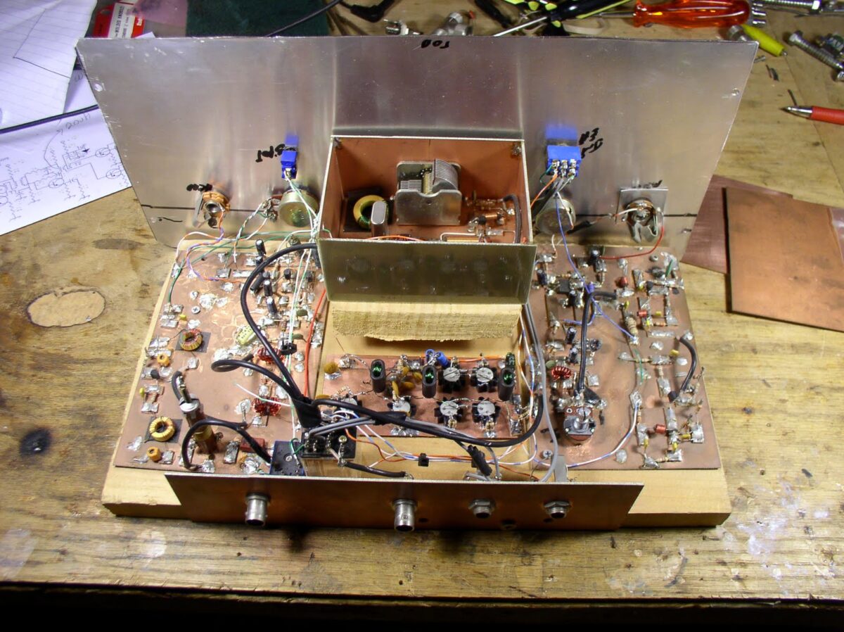
This time I chickened out regarding the possible conductivity of the anodized heat sinks. I didn’t have any trouble with this on my first JBOT, but I worried that if the anodized layer gets flaked away, a heat sink might short one of those collectors to ground. To be on the safe side, I put small squares of Gorilla Tape on under the heat sinks. (PLEASE don’t tell me that Gorilla Tape is conductive!)
For T1 and T2 I used FT50-43 toroids instead of the TV baluns used by Farhan. He had recommended FT37-43’s as an alternative to the TV baluns, but I went with the slightly larger toroids. For T3 I rolled my own binocular core using four FT37-43 toroids stacked 2X2.
The amplifier has passed the smoke test. Next I have to put in the low pass filter (Steve Smith: Please note that I have left space on the board for the filter.) Then this version will face its real test when it goes into the 17 meter Azores SINGLE sideband rig. 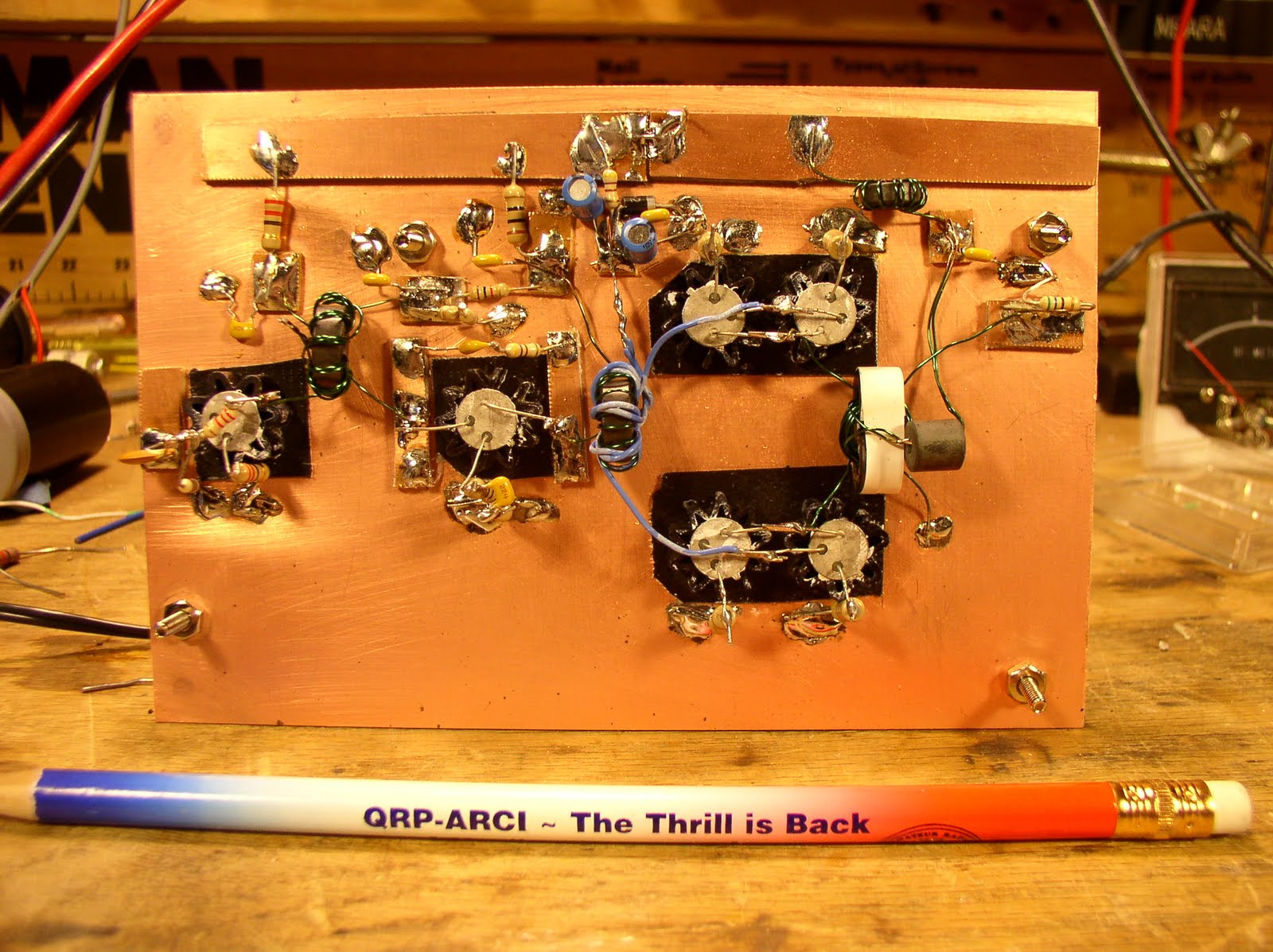 Our book: “SolderSmoke — Global Adventures in Wireless Electronics”http://soldersmoke.com/book.htmOur coffee mugs, T-Shirts, bumper stickers: http://www.cafepress.com/SolderSmokeOur Book Store: http://astore.amazon.com/contracross-20
Another JBOT Amplifier
 Over the weekend I built another JBOT 5 watt linear amplifier (design by Farhan). I used a nice piece of copper-clad board that Dave, W8NF, sent me (thanks again Dave).
This time I chickened out regarding the possible conductivity of the anodized heat sinks. I didn’t have any trouble with this on my first JBOT, but I worried that if the anodized layer gets flaked away, a heat sink might short one of those collectors to ground. To be on the safe side, I put small squares of Gorilla Tape on under the heat sinks. (PLEASE don’t tell me that Gorilla Tape is conductive!)
For T1 and T2 I used FT50-43 toroids instead of the TV baluns used by Farhan. He had recommended FT37-43’s as an alternative to the TV baluns, but I went with the slightly larger toroids. For T3 I rolled my own binocular core using four FT37-43 toroids stacked 2X2.
The amplifier has passed the smoke test. Next I have to put in the low pass filter (Steve Smith: Please note that I have left space on the board for the filter.) Then this version will face its real test when it goes into the 17 meter Azores SINGLE sideband rig. 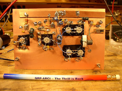 Our book: “SolderSmoke — Global Adventures in Wireless Electronics”http://soldersmoke.com/book.htmOur coffee mugs, T-Shirts, bumper stickers: http://www.cafepress.com/SolderSmokeOur Book Store: http://astore.amazon.com/contracross-20
Amplifier Woes — Help me! Help me!
When I look in the mirror and I see a haunted, obsessed look in my eyes. My wife senses that there is something wrong in the ham shack. She is right. I have an amplifier that wants to be an oscillator. Help me exorcise these gremlins! Guys, this problem is holding up the production of the next SolderSmoke podcast.
My JBOT amp works fine into a dummy load, but when I connect it to an antenna, it gets unstable. Here are some more details of the symptoms:
I am running the JBOT with a 5 element (two toroids, 3 caps) low pass filter (designed by Doug DeMaw and approved by Steve Smith).
With the antenna connected, all is well UNTIL I raise the power out (by varying the input) beyond about 1 watt. Below one watt, the amp is working fine, and it stable. As soon as I hit the 1 watt point, the amplifier seems to break into oscillation. This does not happen into the dummy load.
The antenna is a simple dipole fed by coax. It shows a low SWR. Even when I put an antenna tuner between the amp and the antenna and bring the SWR down to negligible levels, the instability problem persists.
With the amp disconnected from all other circuitry other than the antenna and the power supply, if I just touch the input capacitor, it breaks into oscillation. This does not happen when the amp is working into the dummy load.
I’ve bolstered the power supply filtering and decoupling. No luck. I tried some de-Qing of the transformers. No luck.
Any suggestions?
Our book: “SolderSmoke — Global Adventures in Wireless Electronics”http://soldersmoke.com/book.htmOur coffee mugs, T-Shirts, bumper stickers: http://www.cafepress.com/SolderSmokeOur Book Store: http://astore.amazon.com/contracross-20
Pumpkin Pi and JBOT Gremlins
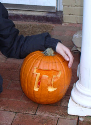 Maria wanted to go with a mathematical theme for this year’s Jack-0-Lantern. Pumpkin Pi!
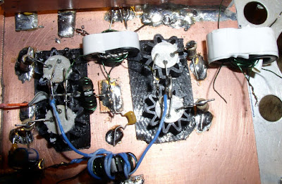
I have been chasing some gremlins and banshees around my old Azores 17 meter DSB rig. The JBOT Amp worked fine into a dummy load, but of course things got a bit more complicated when I put it into the rig and connected it to an antenna. It would take off (like a banshee!) if the load was at all reactive. I think this is the result of inadequate shielding and inputs a bit too close to outputs. But it all settles down nicely when I put a transmatch in the antenna line and tune out the reactance. I may just leave it this way.
Output is a bit low — only about 1 Watt. I realize that at 18 MHz output should be dropping a bit, but I think I should be getting more. I THINK I’m giving it the recommended 1 milliwatt input. At some point I think Farhan mentioned the possible need to experiment with the number of turns on the secondary of the output transformer….
Our book: “SolderSmoke — Global Adventures in Wireless Electronics”http://soldersmoke.com/book.htmOur coffee mugs, T-Shirts, bumper stickers: http://www.cafepress.com/SolderSmokeOur Book Store: http://astore.amazon.com/contracross-20
My JBOT 5 Watt Linear (Farhan’s Design)
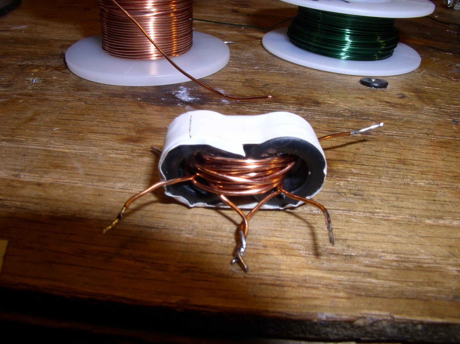
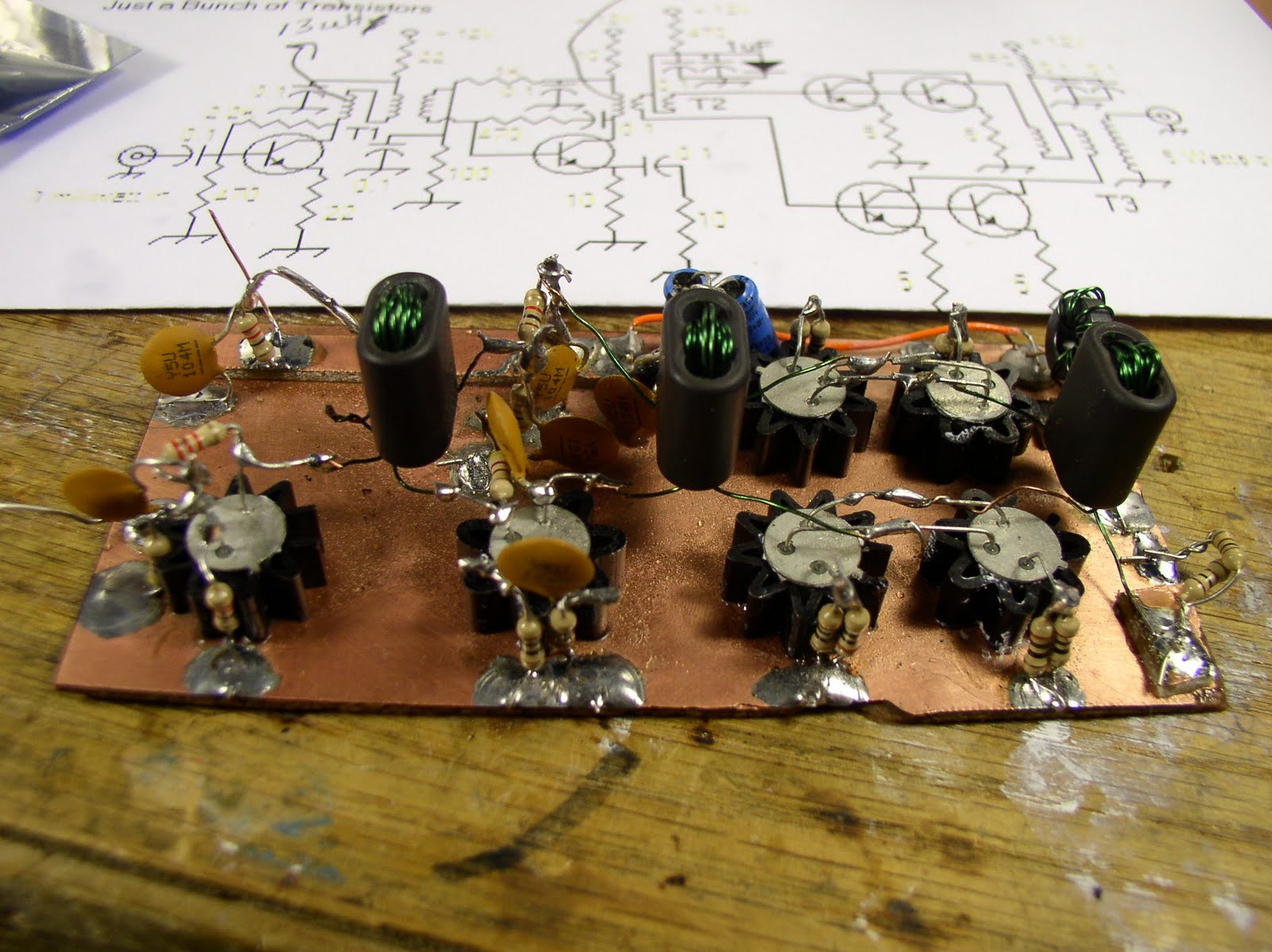 There it is — my version of Farhan’s JBOT 5 watt linear amplifier. JBOT stands for “Just a Bunch of Transistors.” But I think Farhan is being modest. I really like the design, especially the effort to make this something that hams around the world can reproduce from readily available parts. For example, Farhan’s original version used TV balun cores for the transformers. I didn’t have any of those around, but I found three “mystery spec” binocular cores in my junk box. They seem to be working just fine. (I tested them a bit: Farhan had written that FT 37-43 cores would work. T1 has seven turns trifilar. Seven turns on my mystery cores yielded 13uH. On an FT 37-43 core 7 turns yields around 20 uH. Close enough — these are, after all, broadband transformers.)
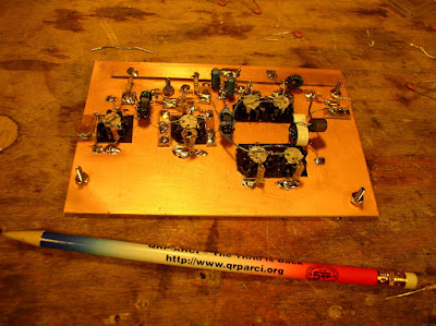
Note how closely my build follows Farhan’s schematic (which you can see in the background). When building this circuit, I just kept Farhan’s web page on my computer screen, and scrolled up and down from his schematic to the photo of his version.
This is the first linear amplifier that worked the first time I powered it up. It didn’t release any smoke, or leave transistor burn tattoos on fingers, or try to be a 14MHz oscillator.
This version is going into my Azores-built 17 meter DSB transceiver. See how nice it fits: Our book: “SolderSmoke — Global Adventures in Wireless Electronics”http://soldersmoke.com/book.htmOur coffee mugs, T-Shirts, bumper stickers: http://www.cafepress.com/SolderSmokeOur Book Store: http://astore.amazon.com/contracross-20
My JBOT passes the Smoke Test
Over the weekend I built my first version of Farhan’s JBOT. I really enjoyed building it. I soldered in the last connections this morning and I am happy to report that it passed the smoke test. More info (and a picture) tomorrow. Thanks Farhan!
Our book: “SolderSmoke — Global Adventures in Wireless Electronics”http://soldersmoke.com/book.htmOur coffee mugs, T-Shirts, bumper stickers: http://www.cafepress.com/SolderSmokeOur Book Store: http://astore.amazon.com/contracross-20
AF Amplifier Selected: From the Ugly Weekender
 We went to ZooMarine yesterday. It is a kind of aquatic amusement park west of Rome. I knew that there would be a certain amount of waiting around while the kids defied gravity. A couple of SPRATs might not have been enough for this job, so, just to be safe, I also took with me the ARRL compendium “QRP Power.” This turned out to be a very good move, because while seated on a bench close to the entrance of the aptly named “Vertigo” ride, I found the AF amplifier circuit that I’ve been looking for (for my WSPR direct conversion receiver). It comes from a June 1992 QST article by Roger Hayward, KA7EXM. The AF amp in his “Ugly Weekender” DC receiver had just what I was looking for: discrete components (no IC’s), an input impedance suitable for a diode ring mixer, and an output impedance suitable for a computer sound card. Thanks Roger! I built the first stage and the active decoupler this morning. They are working fine.
I wanted to find a photo to go along with this article. While doing a Google image search, the cover of one of my favorite books unexpectedly popped up (see above). VE7BPO’s site explains why:
“A great reference for Ugly Constructing is The “Ugly Weekender” by Roger Hayward, KA7EXM and Wes Hayward, W7ZOI published in the August 1981 issue of QST. In fact, it was Wes and Roger who coined the term “Ugly Construction” when preparing this QST article. Wes was asked about this in 2009. The term was a takeoff from the 1958 book entitled The Ugly American by William Lederer and Eugene Burdick. “
I didn’t know there was a connection between our construction technique and the book. I find it very appropriate. The good guy in the book is the “ugly” American. He is a practical, technically-oriented guy who puts his skills to use to help people.
For more background on ugliness see VE7BPO’s (beautiful) site:
http://www.qrp.pops.net/ugly.asp
Class C Amps and the Load and Power Out Formulas
 While up in Rotterdam I started thinking about Class C Amps and the standard formula used to calculate power out and load resistance: Rl=(Vcc–Ve)^2/2Po. I understand why this formula works for Class A amps: The Vcc–Ve term describes the maximum voltage you can get at the output. The rest of the formula is just a version of P=IE and P=E^2/R. The 2 in the denominator converts peak to average. The books tell us that this same formula applies to Class C amps. How could that be? I wondered. Doesn’t the output of a Class C amp look (pre-filter) like a series of pulses at the operating freq? Wouldn’t that require a somewhat different formula?
The answer came from SSDRA and LTSpice. SSDRA page 25 explains “If we assume that the collector voltage varies from zero to twice the Vcc level while delivering the desired output power, the load needed at the collector is given by the familiar relation Rl=Vcc^2/2Po.” (Emphasis added.) The voltage at the collector is being pulled down nearly to zero as the voltage at the base goes positive and the transistor conducts. You can see this in the waveform in the LTSpice screenshot above. Then, when the input voltage dips below about .6 volts, the transistor goes into cutoff and stops conducting. At this point the energy stored in the inductor in collector circuit is dumped onto the collector, raising the voltage there to about twice Vcc. That the ugly spike you see at the top. Wow, you can really see from this the need for output filtering.
As I was exploring this issue, I cam across an old LTSpice VideoCast from December 2006. See below.
BTW: These are the kinds of questions explored in the book “SolderSmoke — A Global Adventure in Radio Electronics.” I’m hearing that delivery is very fast, especially in the UK.
Saturation and Class C Amplfier Efficiency
Originally posted on Gadgeteer News: 10 December 2006
FIRST LTSPICE VIDEOCAST
I made a 5 minute video using a video screen-capture program and the circuit simulator LTSpice. In addition to showing how LTSpice can
be used, the video looks at how saturation affects the efficiency of Class C amplifiers. I put the file on YouTube, but the video quality is poor when viewed through that service (it is difficult to see the graph lines in the YouTube version). So I have also uploaded the 26 meg file (.wmv)
to the http://www.gadgeteer.us web site.