
The last blog postings on Rick N3FJZ were in 2015. Rick sent me a very uplifting reception report, then we had a pretty amazing Homebrew-to-Homebrew contact.
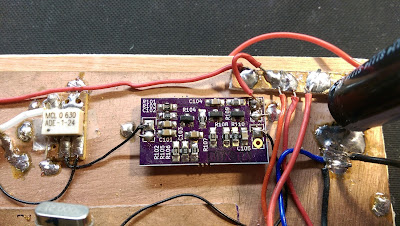
Paul Taylor VK3HN yesterday alerted me to a new YouTube video that shows the progress Rick has made with his homebrew SSB rig.
This is a great example of true amateur SSB construction. Rick is making use of a combination of digital and analog technology. He is adapting circuitry developed by others and using it to meet his needs. During the development stage he is keeping the circuit open (Al Fresco) so that he can easily work on it.
FB Rick.
Category: amplifier theory
Tribal Knowledge: More on Tapping Metal
Back in 2014, when I was putting together my EB-63A solid state amplifier, I had to learn how to tap aluminum so that I could attach my transistors to the heat sink. I did short YouTube video on how I did this (with tales of woe!). This video turned out to be amazingly popular — more than 27,000 views! Apparently there is a great thirst for this kind of knowledge out there. Recently someone in Alaska came across my video and shared with us some more useful information on how to tap metal. Here is some tribal knowledge from Paul KL7FLR:
Hi Bill and Pete,
Stumbled over Bill’s YouTube video about tapping in Aluminum and I would like to add my experience doing such. I have probably tapped over a 1000 holes in various metals, cast iron, steel, aluminum, bronze and brass from 0-80 to ¾-20. Each metal poses its own problems and solutions. There was nothing in error with your video or the method you presented.
My comments:
What causes broken taps is the tap is not being perpendicular to the work. A hole not perpendicular to the work, a worn/dull tap (this applies to the drill bit too) and lack of lube.
Every hole to be drilled and tapped must be perpendicular to the metal. A hand drill electric or battery will not be perpendicular unless two other people can spot the drill operator. Not possible when you are alone in the shop.
Any serious homebrewer should have a drill press. A small bench drill is very inexpensive. Even the $69 Harbor Freight model is adequate for the average ham’s workshop. I see these items at flea markets and on Craigslist all the time cheap. Estate sales not so cheap but sometimes on last day you might get a bargain. Adjustable from 500 to 3600 rpm will cover all the normal sizes of drills. An x-y table could be added ($$) for added accuracy if desired. (search x-y table for examples and sources)
The size of hole you drill makes a difference too. Most drill charts assume you are tapping at 75% of thread contact. This is amount of the male thread of the bolt/machine screw threads contact the female thread in the piece. This is about the max you can expect without some precision tooling that won’t be in the average home shop. 75% provides maximum strength of the fasteners. So unless you’re working on something that requires strength like a tower support bracket or the wings of an airplane you don’t need 75% as 50% thread contact is more than adequate. So when the drill chart shows that a #43 you can instead use a #42 or a 3/32 drill. A little bit larger hole will be a lot easier to tap threads.
The type of tap will also influence the difficulty of tapping threads. The typical hardware store tap is a straight 3 or 4 flute taper tap. The chamfer of a taper tap is 9 threads making tapping much easier. This is the tap for hand tapping. The plug tap has a chamfer of 5 threads and is best used in a tapping head or fixture. The bottom tap is for tapping threads in a blind hole, usually after started with a taper tap. That increases the pucker factor x10. The normal taper tap cuts as it is rotated in a clockwise direction or counter-clockwise for left hand threads. The cuttings will clog the tap and you must back the tap out frequently to clean the cuttings from the flutes preventing the tap from seizing and possibly breaking the tap. Breakage is easily done with the smaller taps but also will happen to a larger tap too. There is a style of tap called a spiral point tap. It will push the cuttings up to the top of the hole and not clog the flutes as easily as the straight flute taps. I still back it out and clean it out of habit. These don’t cost any more than the hardware taps. A 4-40 is about $2.90 the last time I bought one.
Avoid “carbon steel” taps. These will break easier than “high speed tool steel” taps and they are usually a few cents cheaper too.
Lubrication is necessary. Bill’s use of 3-in-1 oil is a good lube but “Tap Magic 20016A Aluminum” fluid is better for tapping aluminum and regular “Tap Magic” for everything else. https://www.amazon.com/Tap-Magic-20016A-Aluminum-Yellow/dp/B00065VEUO
The metal you are tapping can be an exercise in patience. “Hardware” store aluminum comes in various grades from crappy to real crappy. They are of an alloy best suited for the extrusion process and are not wonderful for the tapping process. Aircraft grade aluminum is nice stuff to work with but not cheap. Comes in many grades from 1000 series to 8000 to match the application. Grade 2024 is communally found and is easy to work with while 7075 works like steel. Since most of us won’t be buying a 21 foot stick of aluminum or a 5×8 foot sheet we must take the hardware store grade into account when tapping holes and lean towards the 50% thread engagement, plenty of lubrication and lots of patience. I frequent several aluminum boat building firms and they let me pick through their scrap piles and I’ve made frequent donations of a case of soft drinks or a can of coffee to the break room fund and have also paid the going scrap price for the scrounging privilege.
Worn taps: These get dull with use and will break at the worst possible time and in an expensive workpiece. Broken taps can be removed but are time consuming and require some expertise in doing so. Best to retire them when worn. I used to keep a chart of how many holes a particular tap had been used and at 35 holes for the small taps they got retired. 50 holes for taps larger than ¼”. I once spent over a week of evenings extracting a worn tap from a locomotive cylinder casting. Never again! As my mentor said many times, “dull tools cause accidents and ruined work”.
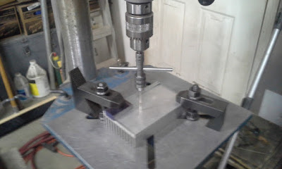
Clamp the work to be tapped stationary if possible. You don’t want it moving around thus inviting a broken tap. Use some method of a tap guide (as Bill did with a block of wood, not great but better than nothing). I use what is called a “Piloted tap wrench”, https://www.amazon.com/Set-Wrench-Piloted-Spindle-Capacity/dp/B077SVQD4S .
Picture is of my setup.
Step 1: Work clamped securely to table at desired hole location.
Step 2: Drill hole.
Step 3: Use piloted tap wrench to tape hole.
Step 4: Done.
WA2EUJ’s NXP RF Power Amplifier Design Challenge Entry — Won First Place Prize!
Congratulations to Jim WA2EUJ. First Place the NXP Design Challenge.
You can buy the board here:
https://sites.google.com/site/rfpowertools/home/nxp-mrf-101
Thanks to Pete Eaton WB9FLW for alerting us to this.
Jan’s FB Slovakian SMD TIA Boards
Hello,
I have put up my SMD version of the TIA amplifier boards online, in case
someone wants it. The files are here:
and direct OSHPark order link:
73!, Jan
The Road to QRO Perdition
I want to start out by saying that this is NOT my fault. I have been TRYING to do QRP things. Remember my recent Tuna Tin 2, Herring Aid 5 rig? I am aware of the ever-present threat of expulsion from the QRP HoF. We all remember what happened to poor Pete back on April 1, 2017.
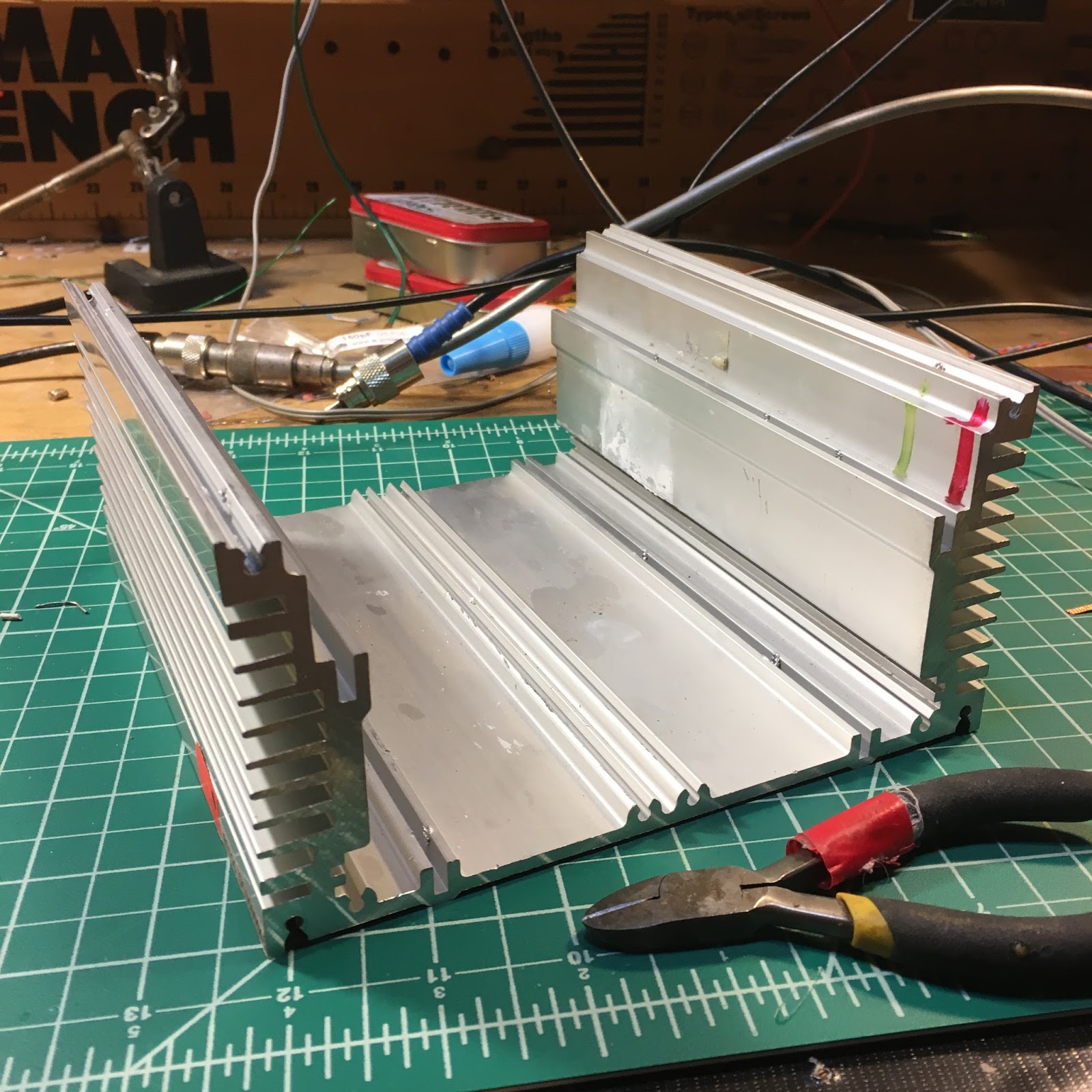
But sometimes people just deliberately put temptation in your path. That is what happened this week. Our old friend Rogier KJ6ETL (formerly known as PA1ZZ) sent me the very LARGE chunk of aluminum that you see in the picture above. Look at that thing. It is practically begging to be turned into a very QRO push-pull amplifier.
At first I told myself that it would be impossible to tap the big heat sinks on the sides. How would I get the drill in there? But then I realized that I can just put the threads in from the outside. I can almost smell the machine oil. And the heat sink compound…
Thanks lot Rogier. This is all your fault.

TRGHS! HB2HB! Homebrew Extravaganza on 40 Meters!
 |
|
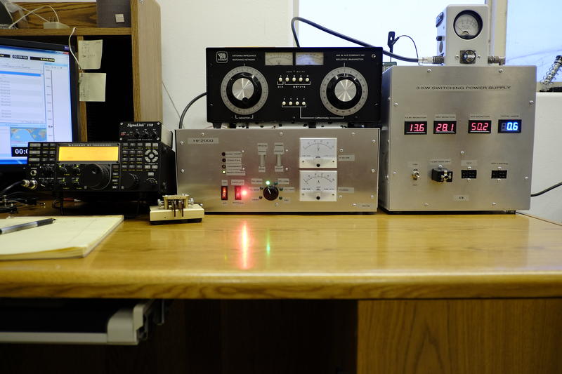
AC7M HB Amp and HB Power Supply
|
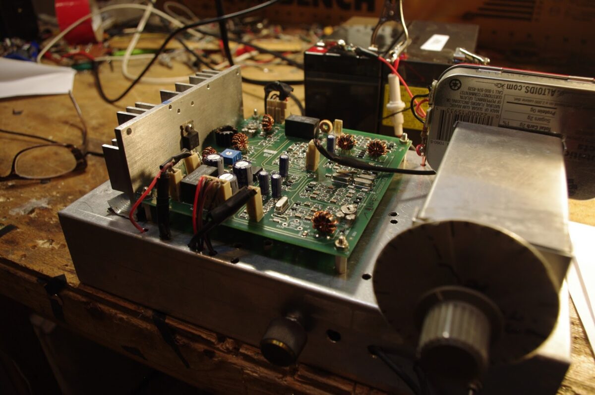
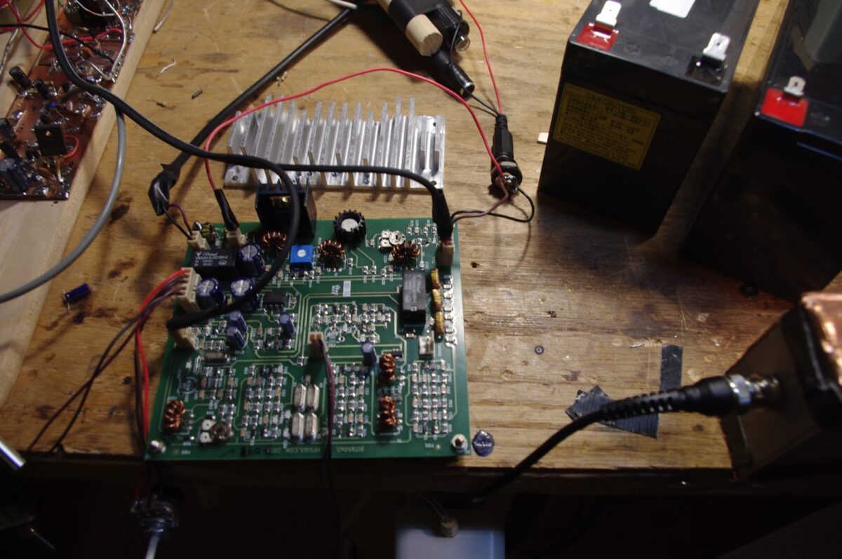
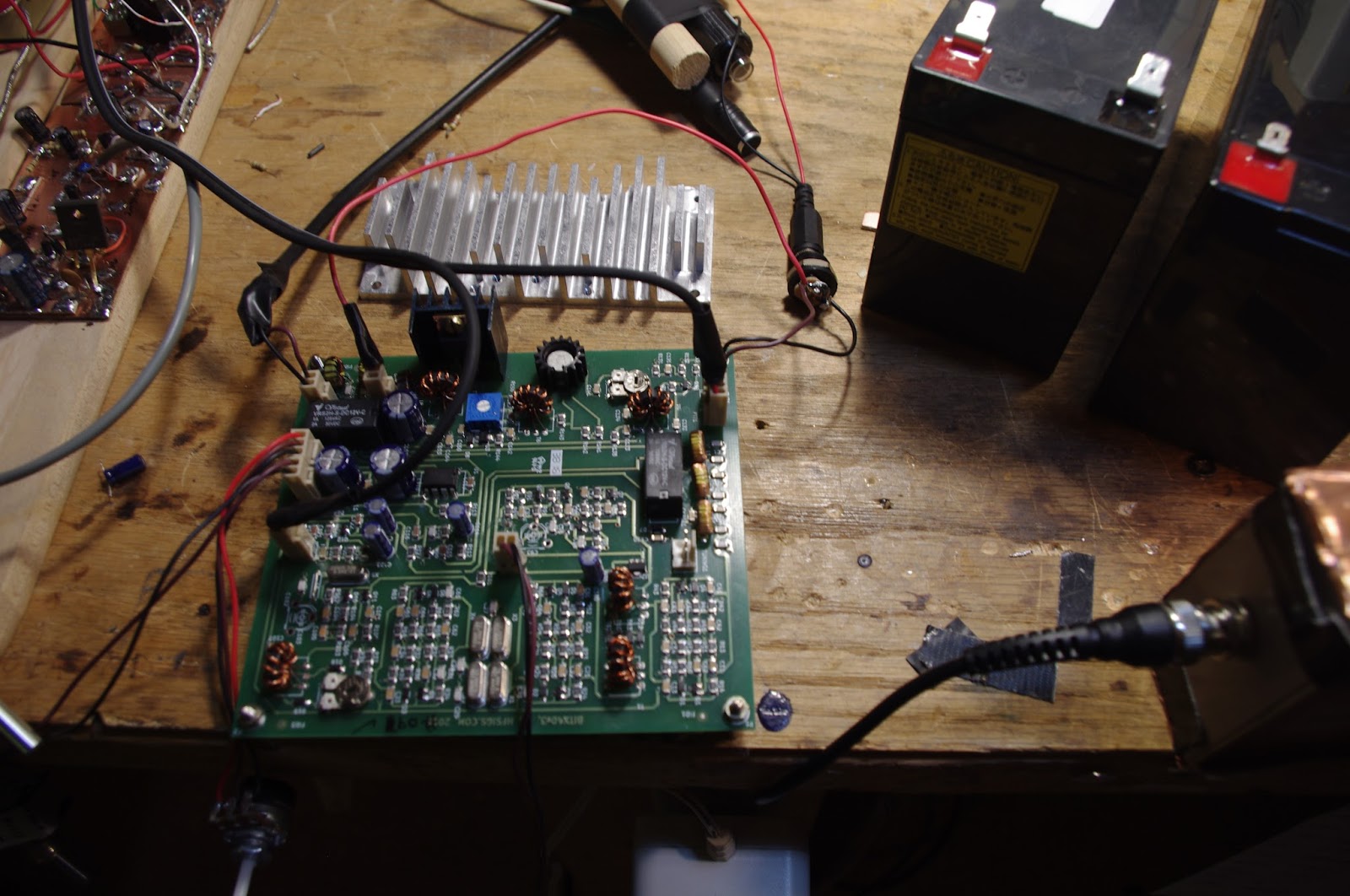
I was flying solo last night. Everyone else in the house was out. So I turned to ham radio for some company. And I was rewarded.
I called CQ with my BITX DIGI-TIA rig and was immediately answered by Doc AC7M in far-off Twin Peaks, Idaho. Doc was running a K3 to a homebrew solid state full gallon amp. And get this — Doc had also homebrewed the 3 kw switching power supply. I looked at my store-bought supply and felt like an appliance operator. I hang my head in shame.
As we discussed solid state amplifiers, we were joined by another builder of silicon after-burners: Don K9AQ, who called in from a beautiful cabin in rural Wisconsin. Don’s amp is based on the venerable EB-104 design.
Both Don and Doc talked about the work of W6PQL. He has a really amazing site devoted to homebrew solid stat amps, and he is selling lots of great boards and parts for this kind of project:
http://www.w6pql.com/
As I finishing up with Don and Doc, I got a very welcome call from an old friend from the SolderSmoke community: Dino KL0S. He as booming in from Williamsburg, Va. Dino has an amazing workshop. He is building a serious vertical antenna for 160 meters. Dino is going for the DX.
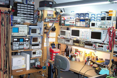 |
| Dino’s Bench |
At this point Mike WA3O in Pittsburgh called in. And get this: Mike heard me on his new BITX 40 Module. The Radio Gods Have Spoken! (TRGHS!). We switched up to 7.285 MHz where I fired up my BITX 40 Module for a BITX40-BITX40 QSO (albeit not at QRP levels).
We should definitely make more use of 7.285 for BITX40 and other HB QRP SSB QSOs. 1930 EST (0030 Z) seems like a good time.
Finally, just when I was thinking that things couldn’t get any better, they did: Armand WA1UQO called in from Richmond. Armand and I collaborate on parts acquisition at Virginia hamfests. We specialize in the contents of the musty cardboard boxes found under the tables. We discussed the DISRUPTIVE influence of Farhan’s BITX 40: All around the world, other homebrew projects are being literally pushed aside on workbenches to make room for that fantastic little module from Hyderabad.
I was very pleased to hear that Armand is building an analog VFO for his module, using a coil in the 4 uH range, wound on a piece of cardboard tube from a coathanger. The inspiration for this kind of coil (which I now have in THREE rigs) came from Farhan, who used sipping straws from fast-food restaurants as coil forms in a sig generator that he built years ago. This week, seeing a Facebook picture of my daughter and me in a restaurant with drinking glasses in front of us, Farhan asked if I had brought home the straws.
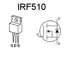
25 Watts From a Single IRF510
I should have tried this a long time ago. It works great. The power supply that I picked up at the Kempton Park rally many years ago happens to have a 25 volt unregulated output. Coincidence you say? I think not. TRGHS.
Farhan provides a really excellent description of how to do this:
http://hfsignals.blogspot.com/p/25-watt-linear-for-40-and-20.html
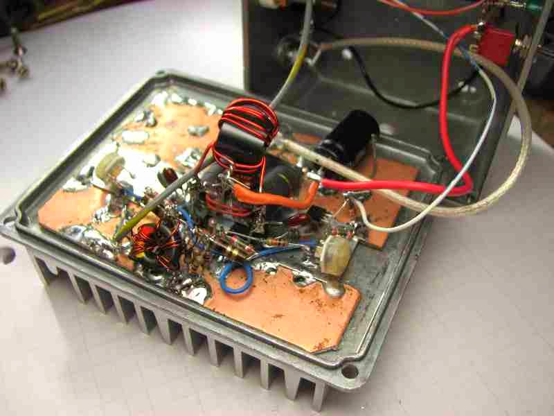
Putting a Heatsink on the BITX40 Module

The fan that I installed yesterday was driving me nuts. It was noisy, both acoustically and electrically. And I would occasionally get my fingers in the blades. Not good. While it did seem to keep the IRF510 from getting too hot, I knew that a real heatsink would do better thermally.
But how was I going to attach the sink to the transistor? That tab on the IRF510 goes to the collector, so if it touches a grounded heat sink, you get a short. A nylon screw and some mylar between the transistor tab and the heat sink is one option. But I didn’t have a nylon screw. So I decided to just keep the heat sink electrically insulated from the chassis.
This project required me to refresh my memory on how to tap a 4-40 hole. I went back and watched the short video I made on the tribal knowledge that Pete had shared with me. Out came the Tap and Die gear and the machine oil. The process went very smoothly.
Here is what I did to get the heatsink in place:
1) After removing the original heatsink, I gently bent the leads on the IRF510 so that the transistors outer edge would be flush with the edge of the PC board.
2) I put a strip of thick tape (Gorilla Tape) along the lower side of the heat sink. This will keep the heat sink from shorting to the chassis.
3) I placed the heatsink where I wanted it, and carefully marked where the mounting screw (through the transistor’s tab) should go.
4) Drill! Tap! (see video) https://www.youtube.com/watch?v=LuqliWT1k5A
5) I applied some heat sink compound (or Desitin!) and then attached the transistor to the heatsink.
6) I put a few drops of glue between the heatsink and the board and the chassis, just to mechanically stabilize it a bit.
7) Bob’s your uncle.
It seems to work great. The MOSFET stays cool. even after long “old buzzard” transmissions. And I notice no stability problems. It was fun to put to use some tribal knowledge and refresh a mechanical skill.
Two Gel Cells and a Heat Sink — BITX40 Power Hack
I blame Pete for this. And Farhan. Pete has been leading us astray with all his talk of high power linear amplifiers (“Two 813s kid, that’s all you need!”). And Farhan practically pushed us beyond QRP limits by placing a separate DC power connector for the IRF510 final amplifier on his new BITX 40 Module board. Farhan writes:
There are jump-points from where you can add more modules like the DDS, more bands, better audio amplifier, etc. Imagination is your limit. You can separately increase the power amplifier’s supply voltage to 25 volts to be more than 20 watts of power : You will have to add a better heat sink. The mods are on the way! (from hfsigs.com)
A while back Chris KD4PBJ sent me some very nice heat sinks — one of those would fit quite nicely on the PA side of the BITX40 board. And I just happen to have two 12V Gel cell batteries. One will power the board and the two together will power the IRF510. With 20 watts out to my dipole I feel confident that I will WIN the upcoming ARRL Phone Sweepstakes (in my category: Homebrew VFO, Northern Virginia).
Design Wisdom from Allison, KB1GMX
Allison KB1GMX has helped me out of numerous battles with recalcitrant amplifiers. She provided an interesting contribution on the r2pro mailing list thread that I referenced yesterday:
Interesting thread…
I see Rick as having provided the basis and tools and it up to the collective ‘US” to use them to
create that next generation radio. All you have to do is decide the performance and
then go about looking at the means to do so. All the blocks are there.
Dynamic range, how much is enough? When I’m portable or mobile raw sensitivity is
more useful as the antenna is usually a compromise. Overload is easy to handle with
switchable attenuator. The exception to this was a radio designed for contesting in a
hostile environment (a KW user 800ft away) if you burn power you get overload
performance. Its not a battery friendly radio (RX power is over 1A for headphone output).
Look at what you need and not what you want.
TX power is just adding stages. I’ve worked MOSFETs, LDMOS, GaN FETS and there
are some pretty cool devices out there and some not designated for RF are cheap.
If all else fails the IRF510 gets both raves and derision. At 12V its a tepid device
but at over 20V and at 24V it starts to wake up and really perform. I’ve run The WA2EBY
design for a few years at 45W level using two of those push pull at 28V and its clean and
solid and the original pair are now over 6 years old! I also run 8 of them (4x4push pull)
at 32V at 6M for a cool 210W with good IMD. I’d add all the good (high gain, low IMD)
power fets perform better at 28 or 50V. For those into CW consider class E as I’ve
worked with this and using GaN fets have generated 15W with 82% efficiency at
13.56mhz (includes driver and osc) and using the lowly IRF510 at 12V a full 10W
with 85% efficiency. Class E can be amplitude modulated.
As to the thermionic FETs, a 6AU6 crystal osc driving a 5763 for 10W gets a lot of raves
on 40M from a buddy that runs CW. The same deal plate modulated can sound good
at 5-6W AM on 75M. For those that want more a 6C4, 6aq5, 6146 will get you over
50W on CW and 25W AM. Change the bias a little and inject IQ SSB into the driver grid
and be running 50-80W PEP. A 12BY7 or 6CL6 driving a pair of 6146 will get you into
the 180-200W DC input range for about 100W. Remember the hybrid radios solid state
low level and rugged tubes for the heavy lifting. The Pi network (or Pi-L) will load anything
from about 28 to 100ohms more if you use enough taps and variable caps. That and DC-DC
converter for the HV are not terrible at 80% or better (even the 1960s transistor designs
were better than 75%).
In the end it all starts with the receiver. For that you can always start with a 1T4 RF and
a 1R4 converter and a 1T4 as regen driving a 3V4 audio. Power it with 45V (five 9V battery)
and a C cell and go portable. It should run for a very long while. Hollow fets run well at low
drain currents. 🙂
Allison
BIG Amplifiers with SMALL Microcontrollers and LOTS of Tribal Knowledge
Hi Bill,
I wanted to forward to you a slightly edited email I sent to one of our podcast listener’s as I think this is a really good example of some “Tribal Knowledge”.
——————————
Hi OM,
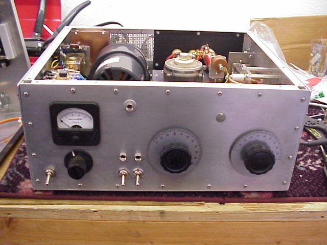
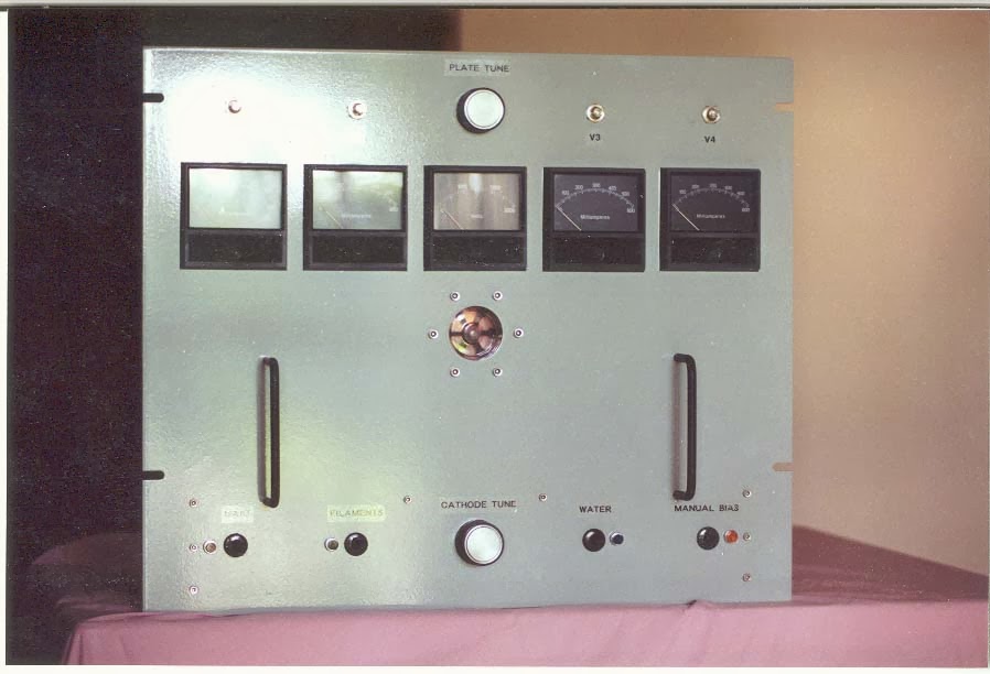
Ham radio publications are much like the Internet –all that is published must be scrutinized. One such publication had a beautiful QRP to QRO amp using a 3CX800A7. A few watts in and 800 Watts out. My daughter was in FM radio broadcasting and I told her to introduce herself to the station engineer and to look out for any pulls – then the floodgates opened –about a week later I had a 3CX800A7.
So I started to work on the amp. The circuits just didn’t make sense and parts were missing that would make it work correctly. I contacted the author and here is what he shared. He built the amp but never did get to proof the final article. In fact he sent me his notes and sketches which were correct. Thus I could have never built that amp using just the article. I built it for one band, 20 Meters. It has a tuned input and a Pi-L output so is quite excellent on harmonic reduction.
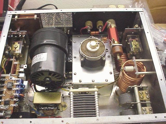
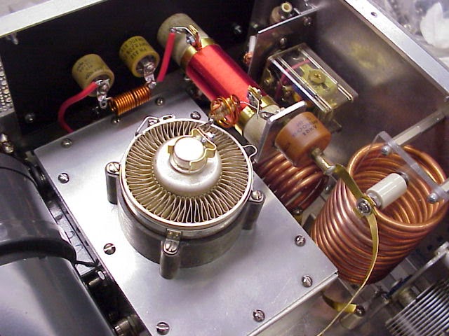
Oh BTW this amp caused me to learn about PIC Microcontrollers. You cannot hit the 3CX800A7 with HV voltage until the cathode is warmed up (must be a female tube). That time delay is 3 minutes. I could not find a suitable time delay relay with a 3 minute delay that didn’t cost an arm and a leg. So that is when I thought about using the PIC16F84 as a time delay relay. Later I ported that over to a 12F675. The cost was less than $10. In the 3CX1500A7 amp ( another free tube) I have two microcontrollers in there. One is used for a three second step start on the filaments (don’t want to shock the filaments with inrush current) and the second for the 3 minute delay before starting the HV step start sequence.
You can see the “Big AMP” on my website at http://www.jessystems.com.
There was only one problem – I was worried about the cooling of the tube so I made sure there was plenty of air which I dump into a very small sub-chassis and the exhaust is out through the tube. Well “Dah” large volume in and small port for exhaust and you have a jet engine sitting on the desk top. Man it was loud – I would wear headphones when it was working. When I built the 3CX1500A7 amp I used a larger plenum so not as loud.
There are several key points I want to make about tribal knowledge:
- Turn off the soldering iron and spend a good deal of time “noodling” over the circuit so that it is clear what each function will do and that all the wires connect to something.
- Contact the author and ask lots of questions and you might be surprised to find out the published design is not what was designed!
- Look for uncommon solutions to build problems. Many times parts used in the articles are so unique that only one exists in the whole world and it is installed in the authors unit.
- The amp was built in 2000 and the use of the PIC16F84 as a time delay for an amp was a bit leading edge but don’t be afraid to employ some advanced technology into your projects. [Today an Arduino built into the amp could do time delay, temperature control of blowers, SWR sensing, grid trip protection and even warm your coffee.]
- In the Big AMP I figured out how to keep the blower going for about 1 minute after the amp is turned off to “cool down” the tube. The point here is to think about not just the amp itself but refinements to make that $600 tube last for a very long time thus filament current inrush protection and tube cool down.
- Don’t forget SAFETY – there is 2000 Volts @ 1 amp running around chassis–it is an electric chair sitting on your desk top. I included a microswitch that when the top cover is off it de-energizes the HV circuits. See if you can spot it in the photos.
73’s
Pete N6QW
PS The amp really does exist –see below.
Our book: “SolderSmoke — Global Adventures in Wireless Electronics” http://soldersmoke.com/book.htm Our coffee mugs, T-Shirts, bumper stickers: http://www.cafepress.com/SolderSmoke Our Book Store: http://astore.amazon.com/contracross-20
Pete’s “Let’s Build Something” Audio Amplifier (video)
Who needs LM386 ICs? Pete goes discrete! Love the MePads. And I knew Pete was going to test it with his finger! He’s just taking stray hum from the power lines and coupling it to the input through that Exacto knife.
Seems to me like these boards is getting close to actually receiving signals.
Our book: “SolderSmoke — Global Adventures in Wireless Electronics” http://soldersmoke.com/book.htm Our coffee mugs, T-Shirts, bumper stickers: http://www.cafepress.com/SolderSmoke Our Book Store: http://astore.amazon.com/contracross-20
OH NO! SolderSmoke Goes QRO! Bill’s Amplifier Project (video)
I got the Communications Concepts Inc. EB-63A amplifier working today. Yea!
Kind of ironic that the highest power amp I have ever built gave me the LEAST trouble. This just goes to show that circuit layout is very important. This amp is a proven design, with a proven layout and board. That’s why it didn’t turn into a 140 watt solid state oscillator!
Our book: “SolderSmoke — Global Adventures in Wireless Electronics” http://soldersmoke.com/book.htm Our coffee mugs, T-Shirts, bumper stickers: http://www.cafepress.com/SolderSmoke Our Book Store: http://astore.amazon.com/contracross-20
WA7MLH’s RD16HHF Amplifier
OK, so now that I have the MOXON in the air, my thoughts are turning to amplifiers and a possible winter project. Hey, even QRP guru Doug DeMaw conceded that every once in a while a fellow needs a few more db. And the sunspot count will be dropping.
On the BITX group there has been an interesting discussion of using RD16HHF MOSFETs in place of our familiar IRF-510s. I thought these devices were new, but some Googling this morning led me back to the wonderful website of QRP giant (hey, he is IN SSDRA!) Jeff Damm, WA7MLH. Jeff has been using these devices for quite some time. As with all of Jeff’s projects, I find his EXTREME UGLY building methods to be inspirational and reassuring. Even if you have been there before, you should visit his site:
Even his QRZ.com page makes you want to build something:
Thanks Jeff!
Our book: “SolderSmoke — Global Adventures in Wireless Electronics” http://soldersmoke.com/book.htm Our coffee mugs, T-Shirts, bumper stickers: http://www.cafepress.com/SolderSmoke Our Book Store: http://astore.amazon.com/contracross-20
Circular Polarity and The Water Wheel in Dale’s Moonbounce Amplifier
Bill:
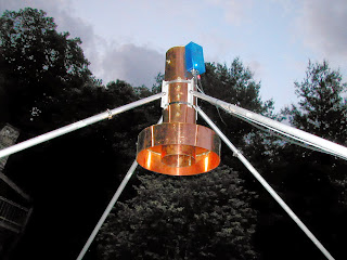
I’ll attach some pix of the feedhorn and LNA for you.
The importance of circular feeds is that as a linear wave passes through the ionosphere, it undergoes Faraday rotation. So it may arrive at the station you are talking to having been twisted 90 degrees. This is a slow progressing process and on all bands except 23cM, may cause EU for example to be locked out for hours at a time for linear stations.
With circular polarity, Faraday is a non issue. The feedhorn almost all of us use is a VE4MA that has separate TX and RX probes. The circular polarity is synthesized as the linear wave propagates down the circular waveguide and encounters sets of capacity stubs. The exact opposite occurs for waves entering the waveguide. The result is we get CW and CCW without having to use any relays (loss) and phasing lines (loss).
My LNA has a noise figure of under 0.24dB and uniquely connects to a protection relay with no cable or adapters (loss).
The position of the feedhorn and its scalar ring is tediously adjusted by measuring the difference between sun noise and cold sky. W4SC developed a very accurate and repeatable process that uses an SDR RX for this.
I use a modified C band satellite drive system known as a polar mount so I only need one motor drive to track the moon.
Anyway, hearing my own echoes off the moon was and still is the highlight of my amateur career.
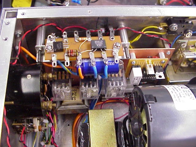
The photos are the feedhorn + LNA, My first water cooled 500W tube amp, my previous 400W solid state amp (mounts right at the dish). My current design is 600W solid state and will also mount at the dish.
BTW, that little circle in the middle of the tube amp is a paddle wheel that turns as long as water is flowing. A tachometer on the wheel sounds an alarm and shuts down plate voltages should the wheel stop turning.
I’ll keep you up to date on my BB RX progress- thank you again Bill.
Dale W4OP
Our book: “SolderSmoke — Global Adventures in Wireless Electronics” http://soldersmoke.com/book.htm Our coffee mugs, T-Shirts, bumper stickers: http://www.cafepress.com/SolderSmoke Our Book Store: http://astore.amazon.com/contracross-20
BITX Build Update #8

Big progress on the BITX: All the bidirectional amp stages are done. A bag of 20 5 MHz crystals arrived from Mouser today. I put one in the BFO/Carrier oscillator and it fired right up. I’ll soon be checking frequencies on these crystals, looking for four that are closest in frequency for use in the filter.
While waiting for the mail I built the audio amplifier for the receiver (lower left corner in the picture above). Here I need some advice/encouragement: In an effort to keep this rig “all discrete” I decided to dispense with the LM386, and replace it with an AF amp using individual transistors. I found a circuit in the 1980 ARRL Handbook that I liked. It has two direct coupled transistors, one NPN, the other PNP. I went with a 2N3904 and a 2N3906. The Handbook said it would yield 40 db gain. I figured this was a close enough replacement for the 46 db gain of the LM386.
As usual, I’m not sure of the impedance matching. I built the first AF stage from the BITX schematic (the stage that precedes the LM386). It goes to a 10K pot. The wiper of the pot would normally go into pin 3 of the LM386. I have the wiper going through a 4.7 uF electrolytic into base of the first transistor. The Handbook says the circuit has an input impedance of 1000 ohms. Does my arrangement sound OK?
Output impedance from this Handbook circuit is also 1000 ohms. I tried it with some HI-Z headphones that I have, putting AF in from my Maplin AF sig generator. It sounds OK. Not a LOT of audio available. But OK. I may need one more stage to drive a speaker.
Our book: “SolderSmoke — Global Adventures in Wireless Electronics” http://soldersmoke.com/book.htm Our coffee mugs, T-Shirts, bumper stickers: http://www.cafepress.com/SolderSmoke Our Book Store: http://astore.amazon.com/contracross-20
VE7BPO on “Killing Q”
I’m still scratching my head a bit about HOW the resistor prescribed by Edgardo, LU1AR, cured the 250 kHz oscillation problem that was plaguing the JBOT amplifier in my 20 meter DSB rig. Earlier I’d posted an excerpt from a CQ article in which Doug DeMaw talks about swamping and Q killing. Last week I got a very thoughtful e-mail from esteemed homebrewer Todd, VE7BPO. Here is an excerpt :
Thoughts and Considerations
Let’s discuss squashing low frequency oscillations in a QRP transmitter; say at 200 KHz or so. A low value resistor across the coil (12t — FT37-43) often works well to stop these.
Oscillations come from the transistor: gain versus frequency isn’t linear, nor is impedance at transistor ports. We’ll often add negative feedback and such to stabilize an amplifier towards unconditional status. In my Tx circuit that oscillated, no feedback was applied.
In the case of an inductor wound on a FT37-43 or FT50-43, the Q is already low (say 8- 15 or so). Obviously a resistor in parallel with such a coil is not going to lower Q since Q is already quite low. That R will reduce the inductor impedance and thus may serve to decrease the low frequency gain of the RF amplifier to stop any low frequency oscillations. This might not work so well with a way-high fT transistor where decoupling might be hampered if UHF oscillations are singing.
Doug DeMaw often referred to the parallel resistor as a Q-killer. If we examine the equations describing parallel, or series resonant circuits — if the Q of a tank is high enough, we can practically ignore the effect of resistance at resonance. Conversely if we add a resistance and make it high enough, we might even obliterate the resonant frequency or “kill the Q”. Engineers have long placed an R into a parallel-tuned circuit to drop Q and stop oscillations — they refer to it as damping. 1 example might be in old TV sets where a variable resistance was added to peaking coils to prevent a tank from ringing at a frequency determined by the coil L and distributed C. This applies to higher Q inductors and not our FT37-43 inductor.
Decoupling
Our teacher, Wes, teaches us in EMRFD that coupling often occurs along the DC power supply lines. Further, he’s taught us to decouple AC by placing high impedance in this path. Often the impedance is a low-pass filter with series element(s) of a high Z and shunt element(s) with a low Z. The filter must present a simple short circuit (or perhaps just a resistance) at low frequency so DC flows to the amplifier.
Final
Oscillations should likely be identified and treated according their frequency. This topic looks advanced and all RLC networks deserve more attention from us.
Todd, VE7BPO — Feb 27, 2013
Our book: “SolderSmoke — Global Adventures in Wireless Electronics” http://soldersmoke.com/book.htm Our coffee mugs, T-Shirts, bumper stickers: http://www.cafepress.com/SolderSmoke Our Book Store: http://astore.amazon.com/contracross-20
A Christmas Present from Argentina

There is an old saying in Spanish: “No hay mal que por bien no venga.” More or less this is the same idea as: “Every dark cloud has a silver lining.” Well, the dark cloud was my techno-agony with the parasitic oscillations (see below). The silver lining was the e-mail from Edgardo, LU1AR, in Buenos Aires that helped me get rid of them. Edgardo advised putting a resistor across the primaries of the JBOT amplifier stages. This is an old “lower the Q” trick, the idea being that lowering the Q might help prevent the amp from self-oscillating. I used 680 ohm resistors. First I put one across the primary of Q1. No joy. Then Q2. No luck. Then I put one right across the primary of that big output transformer. That did it! The parasitics disappeared. And I still get a nice 4 watts of output. Thanks Edgardo. I hope to make a contact with this rig today.
The real silver lining in this story comes, however, in the form of Edgardo’s blog site. Wow, what an inspiring example of Argentinian Knack. Radios, telescopes, auto-giros. This guy is also into homebrew DSB rigs. Wonderful stuff. Check it out. (Google will translate it for you, if necessary, but even if you don’t read Spanish, the pictures tell most of the story.)
http://www.lu1ar.blogspot.com.ar/
Thanks to all who sent advice and encouragement. Merry Christmas!
Our book: “SolderSmoke — Global Adventures in Wireless Electronics” http://soldersmoke.com/book.htm Our coffee mugs, T-Shirts, bumper stickers: http://www.cafepress.com/SolderSmoke Our Book Store: http://astore.amazon.com/contracross-20
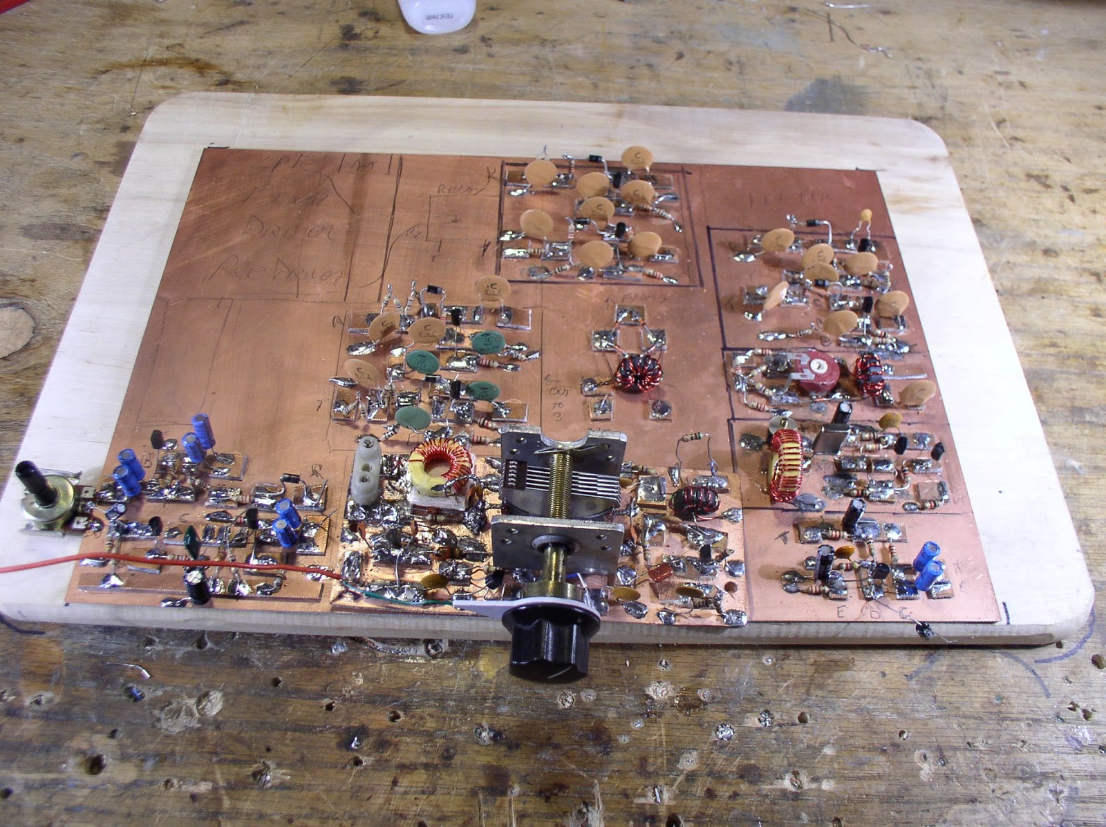
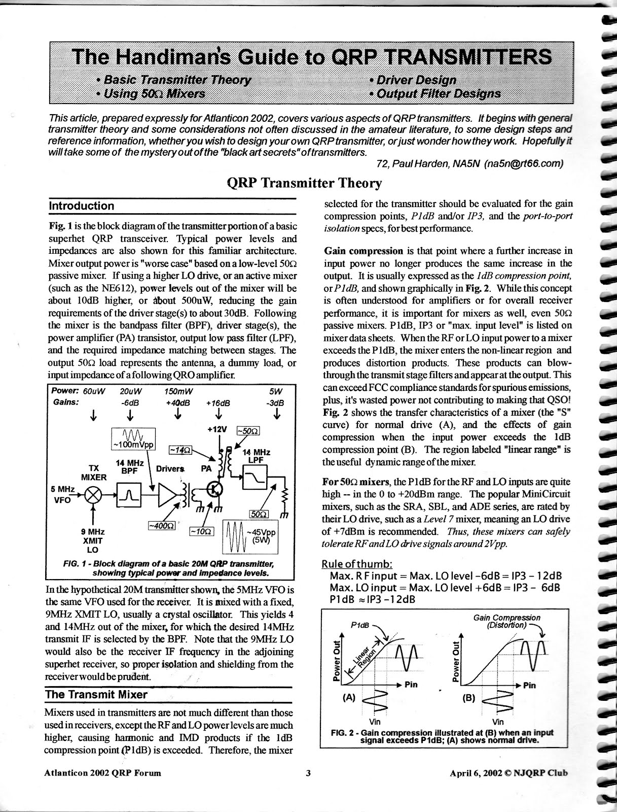
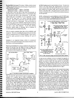
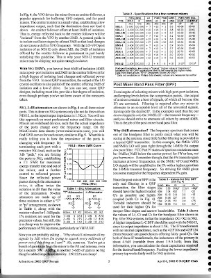
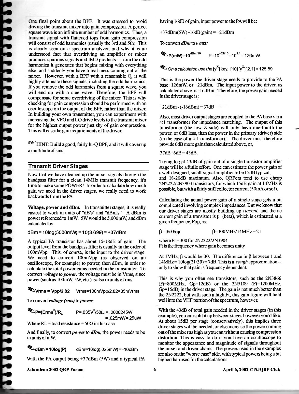
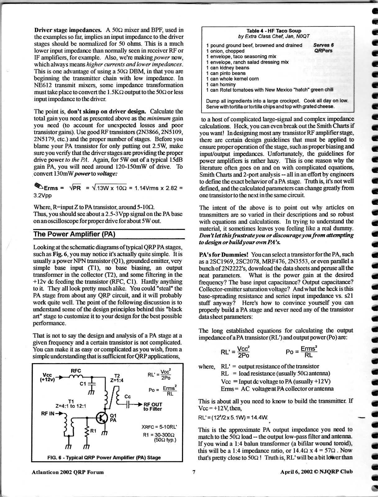
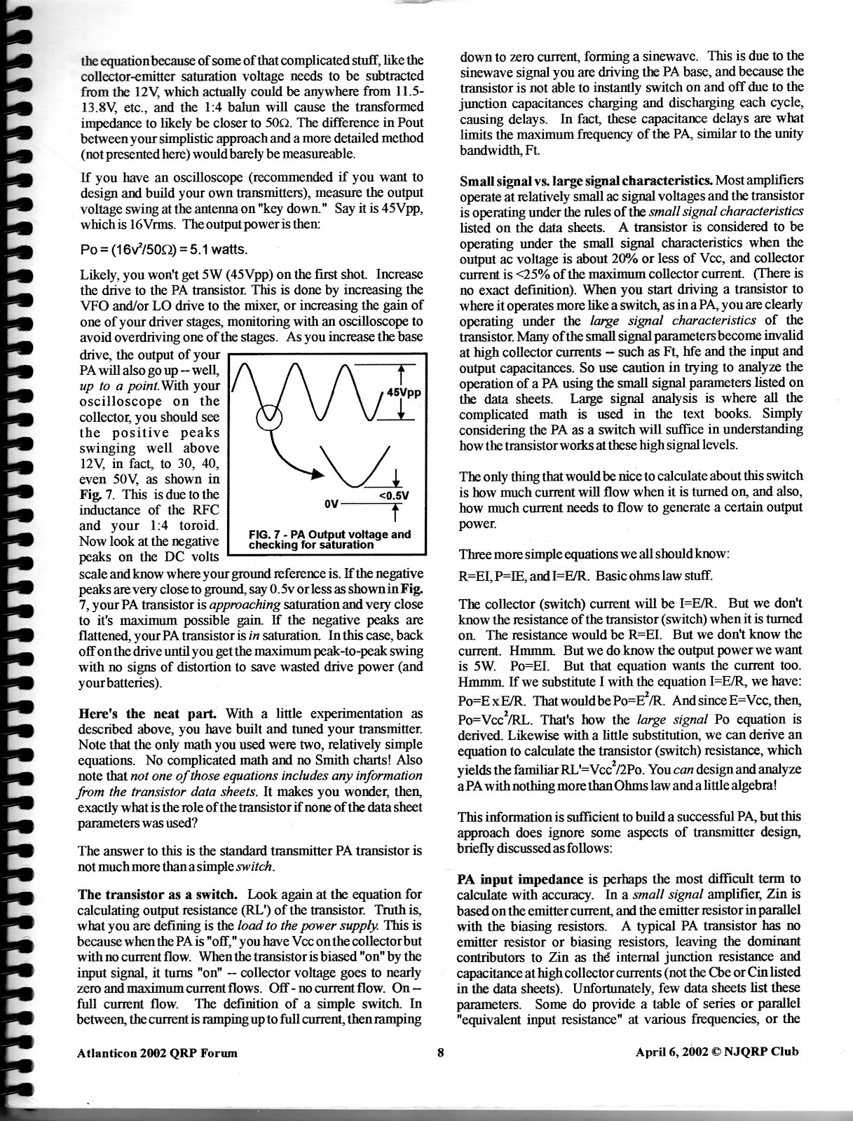
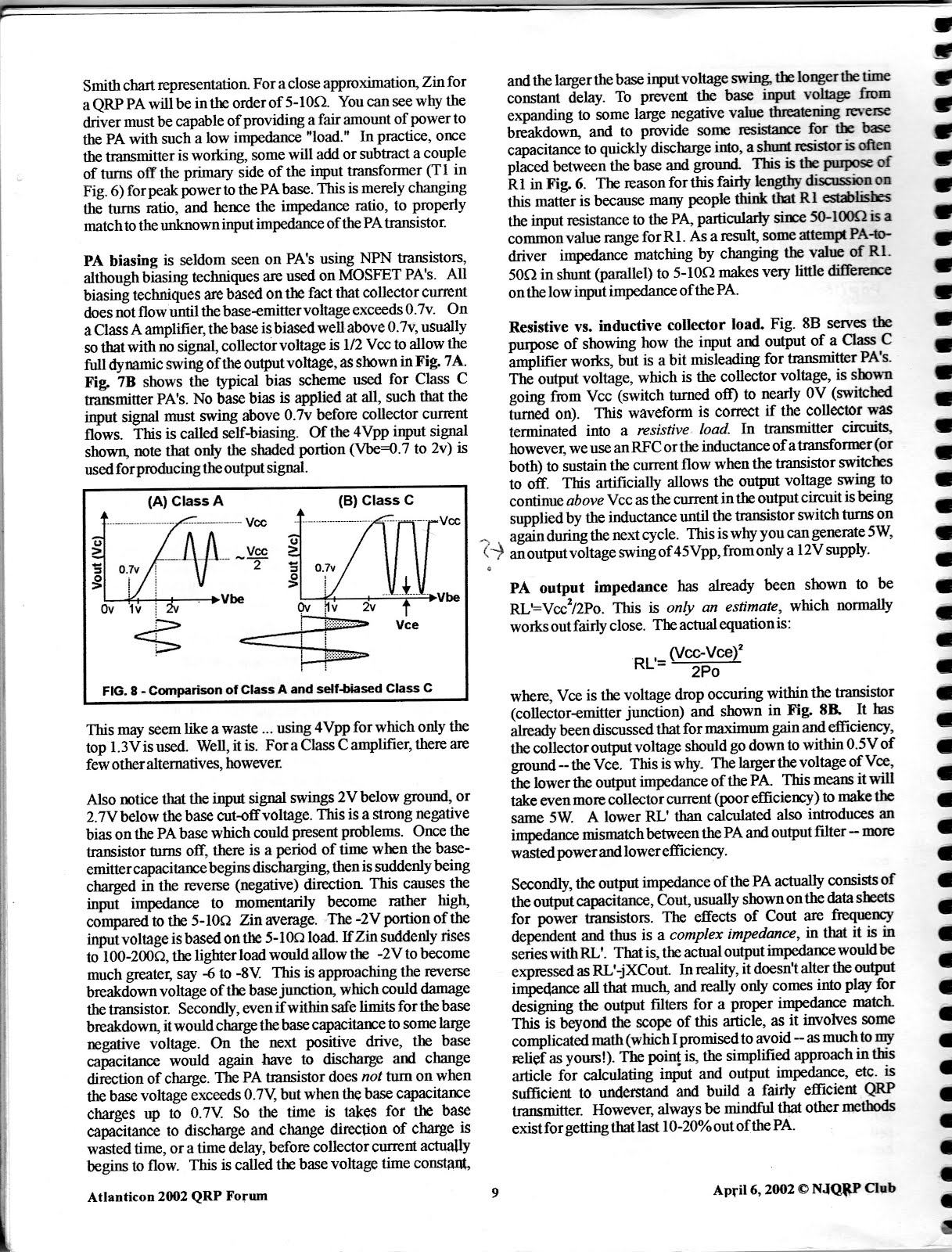
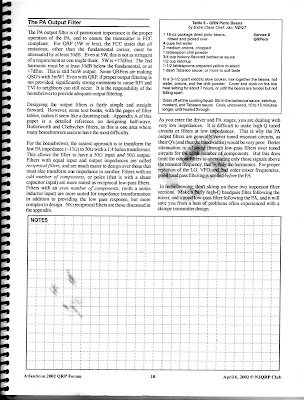
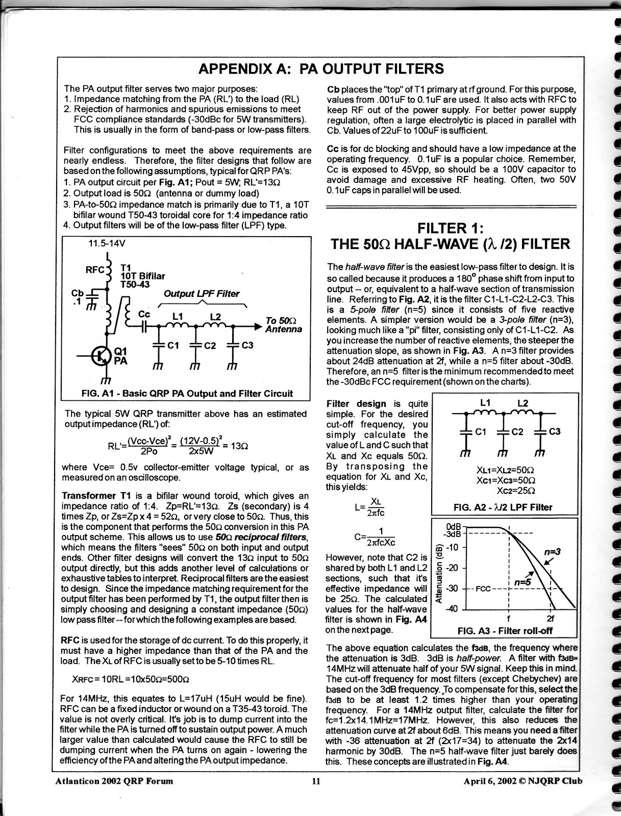
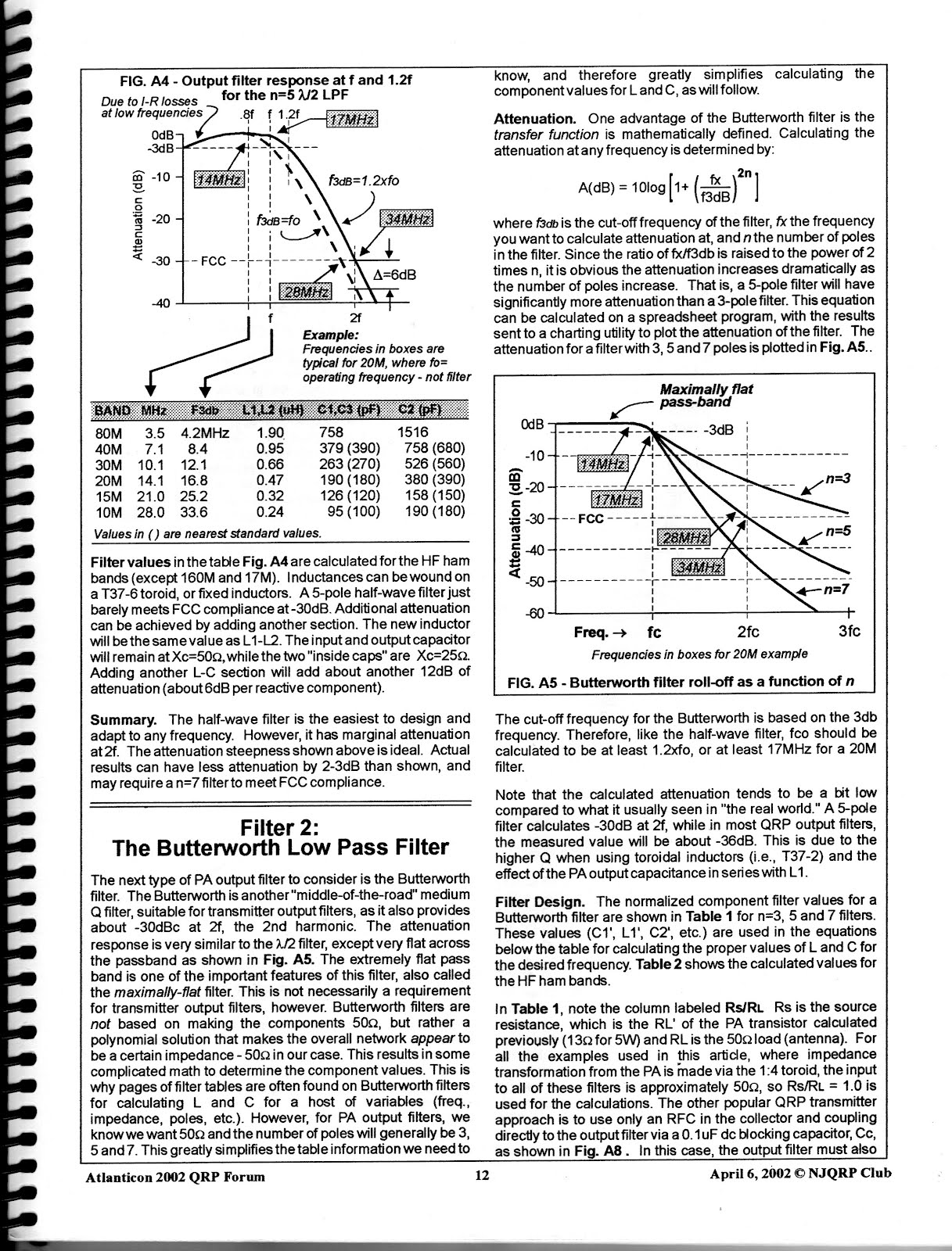
NA5N’s Handiman’s Guide to QRP Transmitters


This magnificent article came out of the 2002 Atlanticon QRP forum. I think George Heron, N2APB, had sent me a paper copy of the “Proceedings” from that event. I got a hold of it just around the time that was trying to deepen my understanding of transistor amplifier theory. Paul’s article was a huge help. There then ensued a long on-and-off e-mail discussion of the article, and of the need to make an e-version of it available to the wider world. I lost track of where we ended up, but I remember Paul being very pleased with the feedback.
Here it is! Thanks Paul!
Our book: “SolderSmoke — Global Adventures in Wireless Electronics”http://soldersmoke.com/book.htmOur coffee mugs, T-Shirts, bumper stickers: http://www.cafepress.com/SolderSmokeOur Book Store: http://astore.amazon.com/contracross-20
Hard Core! Wisdom and Ideas on Toroids
 Gerard ZS5AAC
This morning the BITX20 mailing list has an interesting discussion of toroidal cores. I especially like Gerard’s use of the cores from old CFL bulbs. Farhan wraps it up with a great explanation of why we use ferrite cores in broadband transformers:
——————————
Over the years I built quite a few BITX’s. In the beginning I used the
toroids salvaged from CFL lamps. These worked quite well for the mixer
coils. For the filter coils I used 6mm bakelite slug tuned coils that were
stripped from old PYE radios. Wonder if anybody else experimented
along the same lines. I build my BITX’s Manhattan style and they work from the start with few minor tunings. Happy BITX’ing, Gerard, ZS5AAC.
—————————————
Bob
The purists may attack us on this, but what you propose is very
possible. I have been using a wooden-core toroid for several years as part of an antenna tuner.
http://qrp.webhop.net/Pictures/Webcam-1293651325.jpeg
http://qrp.webhop.net/Pictures/Webcam-1295140555.jpeg
I’m also using small plastic and wooden beads as toroid cores for
several other projects. Half inch long sections cut from thick-wall (schedule-40 or schedule-80) PVC pipe also makes good toroidal forms. Beauty of using non-metallic cores is that the core can be split to allow winding wire through the slot without having to thread it through the hole.
http://qrp.webhop.net/Pictures/Webcam-1289957121.jpeg = 1.4 uh
Bending an inductor back on itself in toroidal form concentrates the
magnetic field in the center, whether the core is metallic or non-metallic. This gives you similar self-shielding properties when using either type core material.
With non-metallic cores you no longer have to worry about core saturation, so running high current finals is not a problem.
Key to doing this is being able to measure inductance of 5 turns, 10 turns,
and 20 turns, so you can calculate and plot the effective AL of your wooden core toroids. Once you know this value you can make up a chart to tell how many turns are required for a specific inductance.
Twisting wires together to make a transmission-line for bifilar or
trifilar windings is interesting because the impedance of that transmission line might affect performance of your transformer. It may require a bit of experimentation with an SWR bridge to tell when you have the best balance between twist pitch, wire diameter, and insulation thickness.
Arv – K7HKL
———————————————
Robert, Arv,
There are two types of coils used in the bitx – the broadband
transformers and the RF coils in the bandpass filter and oscillators.
You could easily substitute the rf and vfo/bfo coils with just about
any kind of coil – as long as you are hitting the same inductance and
Q. But there is a catch : a few years ago, I finally got down to
measuring the Q of the nylon tap washers that I had originally used.
The q was quite modest at 70. Wes made independent measurements with similar results (his paper is on www.w7zoi.net under technical stuff). In short, for good performance use good old air coils wound on a
cylindrical formers if you don’t use toroids.
About the broadband transformers. These need a material that has very
low loss, very high permeability. The reasoning is like this :
1. We need an transformer’s inductance such that the reactance is
at least 200 ohms at the lowest frequency. This puts the inductance at
around 30uH at 4MHz.
2. If we achieve 30uH through lots of turns (say 100), each turn will
exhibit capacitance with it’s neighbor and the large number of turns
will add up the capacitance so that the coil will provide enough
self-capacitance to resonate at an unintended frequency in HF leading
to pretty bad mixer performance.
3. The only way out would be to achieve the required reactance with
lower number of turns. This means using ferrites.
– farhan VU2ESE
Our book: “SolderSmoke — Global Adventures in Wireless Electronics”http://soldersmoke.com/book.htmOur coffee mugs, T-Shirts, bumper stickers: http://www.cafepress.com/SolderSmokeOur Book Store: http://astore.amazon.com/contracross-20