 |
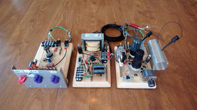
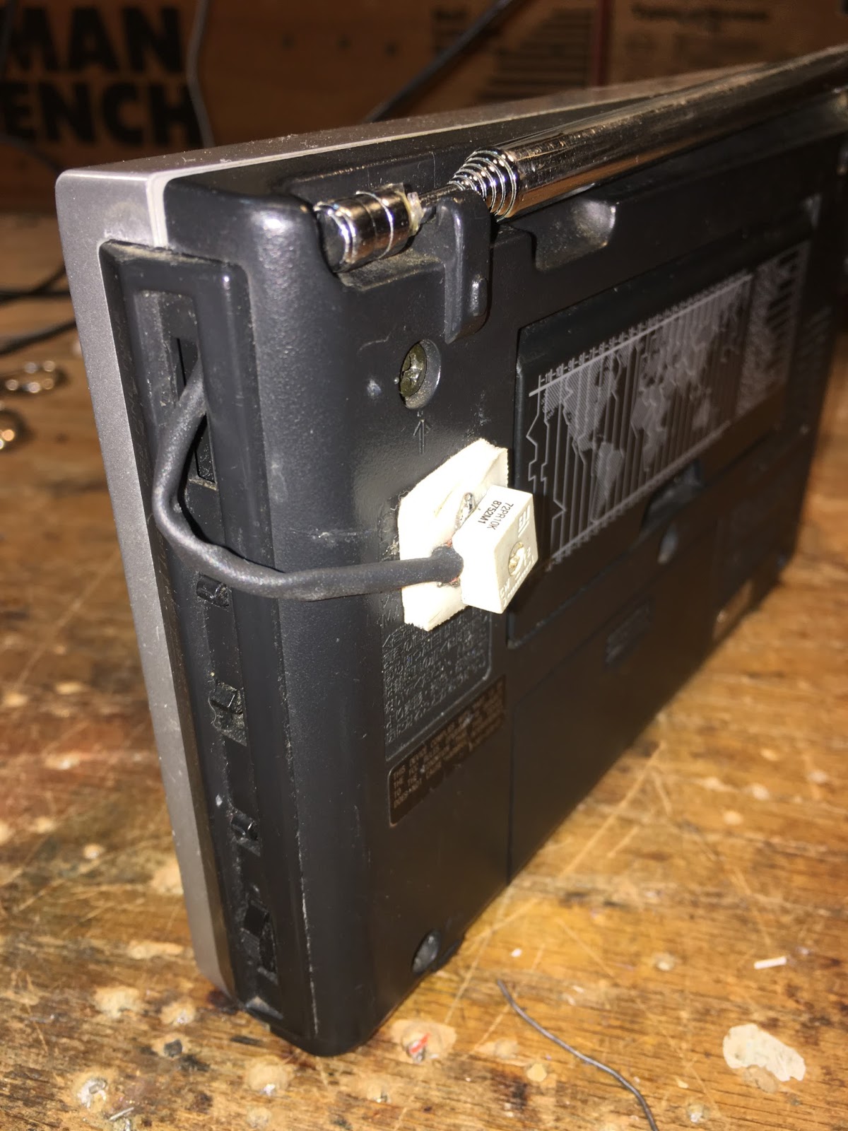
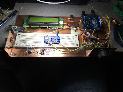
| Bill’s Bavaro DR Beach Station uBITX in the box, HB key |
SolderSmoke Podcast #217 is available:
1 February 2020
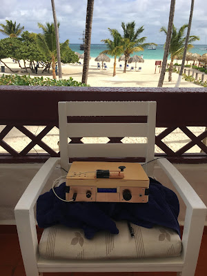
Travelogue! Dominican Republic trip. uBITX on the Beach. EFHW. LiPo Battery. First contact of the new year.
Bill’s Bench Report
Following up on proposed uBITX mods:
— Put pot on sidetone line from Raduino to keep the sidetone a bit quieter.
— Fixed the key — pounding brass
— Will install 4 States QRP Active AF filter.
— Need to reduce power on CW to 5W
— Stereo to mono headphone adapters.
— Turning off display and mic amp circuit not really worth it — they don’t pull much current.
Pete’s Bench Report:
ELMAC Power Supply project
1930s era transmitter?
Teensy and SDR
PETE’S IDEA ABOUT GETTING LSB AND USB FROM BITX40
KWM-2 suggestions
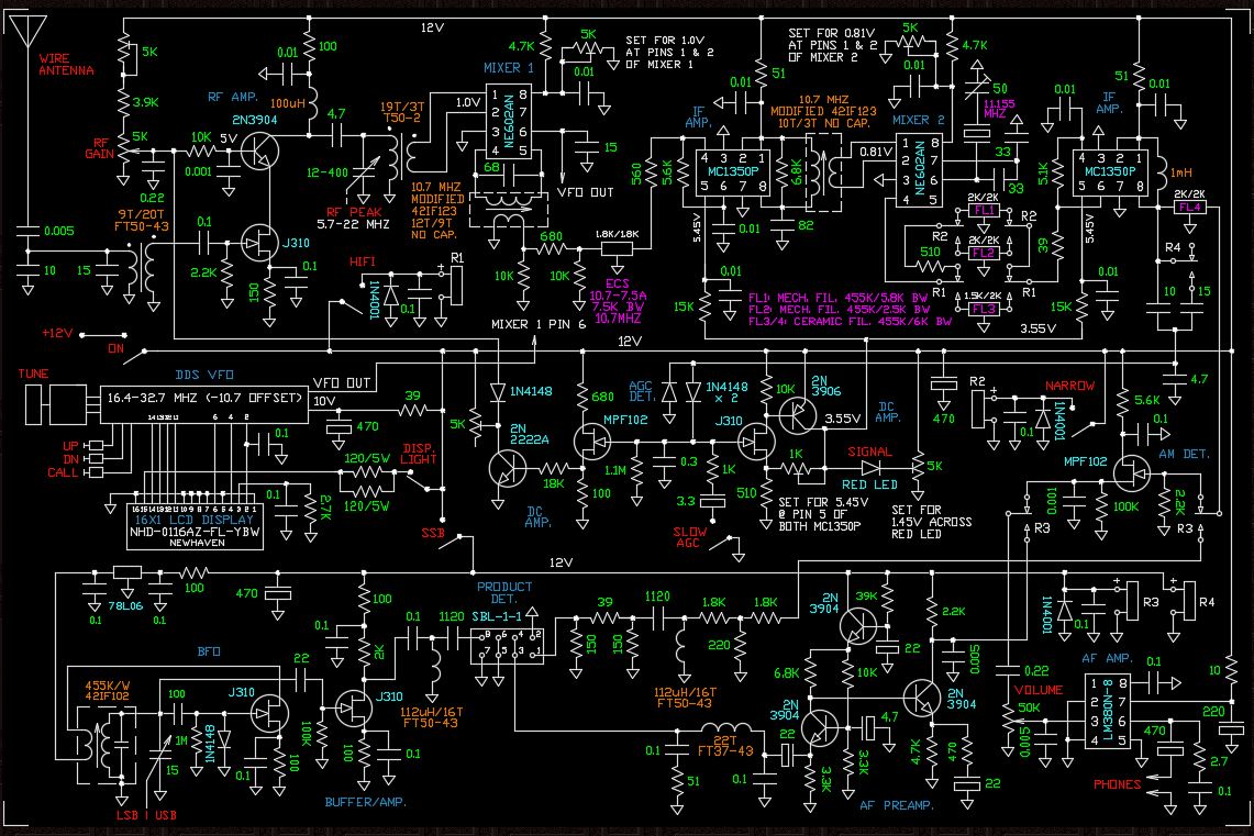
Back to Bill’s Bench:
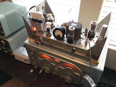
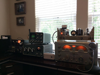
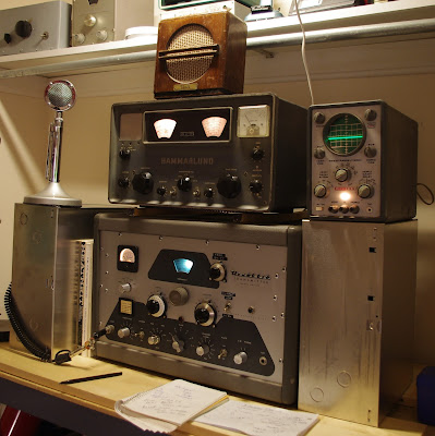
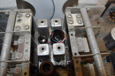
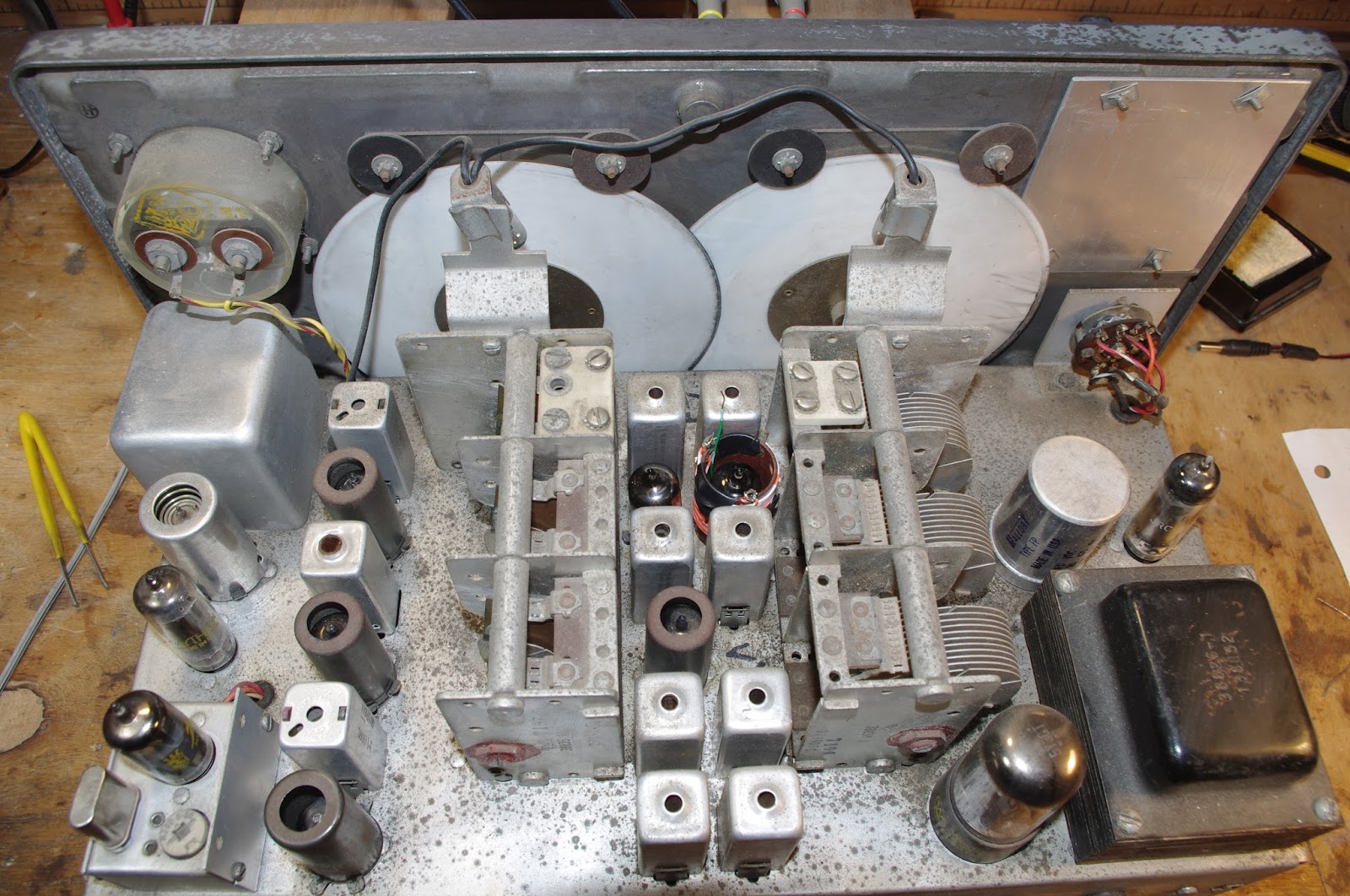
Working on HRO-ish Receiver.
Bad SBL-1
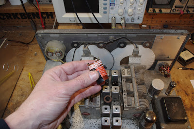
Got idea for wider ceramic filter from Paul VK3HN
Ordered parts from Mini-kits in Australia. They sent 6kc filters.
Bruce KK0S sent me some 10 kc filters too.
Installed 6 kc filter with L network matching networks. Works great.
Also installed Infinite Impedance Detector that Paul used.
Needed some additional amplification ahead of the IID, so I used one stage of BITX amp.
Works great. I can tune full 40 meter band AND 49 meter SW band. Radio Romania, China, Radio Marti, Brazil, South Carolina.
Beefed up the shielding to cut down on AM detection.
MISCELLANY
— AM and DSB in LTSpice
— Duly Noted: Paul VK3HN’s RIG: “THIS MACHINE KILLS KILOWATTS”
Kanji YC3KNJ’s QRPesso Expresso Coffee in the field
— The DANGERS of powerful magnets.
MAILBAG:
–KK4DAS Dean doing great things. MMM heard at Penn State. Where is the rest of the CBLA?
— Thanks to Don for kind donation to the SolderSmoke cause
— Dale BA4TB — First SolderSmoke feedback from China. Thanks Dale!
–Steve Silverman: Sideswipers and bugs were made to handle “carpal tunnel of the day” So do I need a keyer for casual CW work?
— Peter VK8VWA on the limited knowledge gained from kit building. Listens to podcast while walking on the beach in Australia.
— Allan Hale — Clothes Pins as Toroid holders. Yes! More Clothes Pins Wild Woody Keys from Dave Ingram
— Pete WB9FLW 100 Watt Amp from WA2EUJ
— Dave Wilcox K8WPE A medical question: Does the Michigan Mighty Mite work differently depending on what kind of medicine was in the pill bottles used for the coil form? Good question Doc! Dave suggest that putting CBD on the coil or the crystals. Anything to mellow out the ham bands…
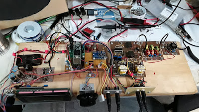 |
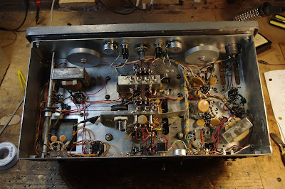
| Pete’s Plank SDR When you know stuff, you can do stuff! |