But why? Why Can’t I Listen to DSB (or AM) on my Direct Conversion Receiver?

I’ve said this before: I just seems so unfair. We just should be able to listen to DSB signals with our beautifully simple homebrew Direct Conversion receivers. I mean, building a DSB transmitter is a natural follow-on to DC receiver construction. And we are using AM shortwave broadcast stations (Radio Marti –I’m looking at you) to test our DC receivers for AM breakthrough. But when we tune these stations in, they sound, well, awful. So unfair! Why? Unfortunately it has to do with laws. Laws of physics and mathematics. Blame Fourier, not me.

Over the years there has been a lot of handwaving about this problem. From Doug DeMaw, for example:

In his “W1FB’s Design Notebook,” Doug wrote (p 171): “It is important to be aware that two DSSC (DSB) transmitters and two DC receivers in a single communication channel are unsatisfactory. Either one is suitable, however, when used with a station that is equipped for SSB transmissions or reception. The lack of compatibility between two DSSC (DSB) transmitters and two DC receivers results from the transmitter producing both USB and LSB energy while the DC receiver responds to or copies both sidebands at the same time.”

That’s correct, but for me, that explanation didn’t really explain the situation. I mean we listen to AM signals all the time. They produce two sidebands, and our receivers respond to both sidebands, and the results are entirely satisfactory, right? Why can’t we do this with our Direct Conversion receivers? I struggled with this question before: https://soldersmoke.blogspot.com/2015/07/peter-parker-reviews-dsb-kit-and.html You can see in that post that I was not quite sure I had the answer completely correct.

It took some discussion with a fellow Vienna Wireless Society member, and some Googling and Noodling for me to figure it out. But I think I’ve got it:

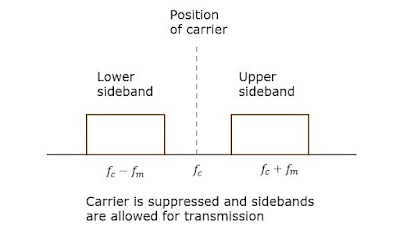
Imagine a station transmitting a DSB signal at 7100 kHz with a 1 kHz tone at the AF input. There will be signals at 7101 kHz and at 7099 kHz. Assume the carrier is completely suppressed.

We come along with our DC RX and try to tune in the signal.

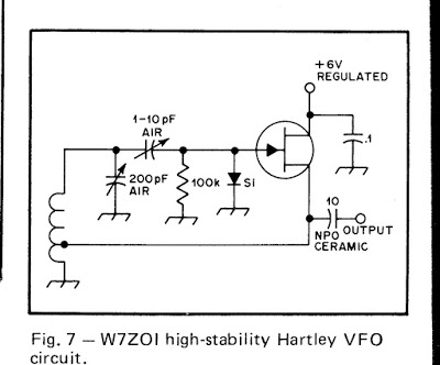
Remember that they heart of the DC RX is a product detector, a mixer with the VFO (or PTO) running as close as we can get it to the suppressed carrier frequency (which we can’t hear).

Lets assume that we can somehow get our VFO or PTO exactly on 7100 kHz. The incoming signals will mix with the VFO/PTO signal. We are looking for audio, so we will focus on the difference results and ignore the sum results of the mixing.

The difference between 7101 and 7000 is 1 kHz. Great! And the difference between 7099 and 7000 is 1 kHz also. Great again, right? We are getting the desired 1 kHz signal out of our product detector, right? So what’s the problem?

Here it is: SIDEBAND INVERSION. Factoring in this part of the problem helps us see the cause of the distortion that plagues DSB-DC communication more clearly.

Remember the Hallas Rule: Whenever you subtract the modulated signal FROM the unmodulated signal, the sidebands invert. So, in this case, we are subtracting that 7099 “lower sideband” signal FROM the 7100 VFO/PTO signal. So it will invert. It will become an upper sideband signal at 1 kHz. We will have two identical 1 kHz signals at the output. Perfect right? Not so fast. Not so PERFECT really.

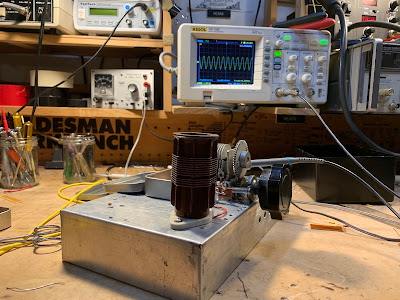
The perfect outcome described above assumes that our VFO/PTO signal is EXACTLY on 7100 kHz. And exactly in phase with the suppressed carrier of the transmitter. But if it is even SLIGHTLY off, you will end up with two different output frequencies, signals that will move in and out of alignment, causing a wobbling kind of rapid fade-in, fade-out distortion. You can HEAR this happening in this video by Peter Parker VK3YE, starting at 6:28:

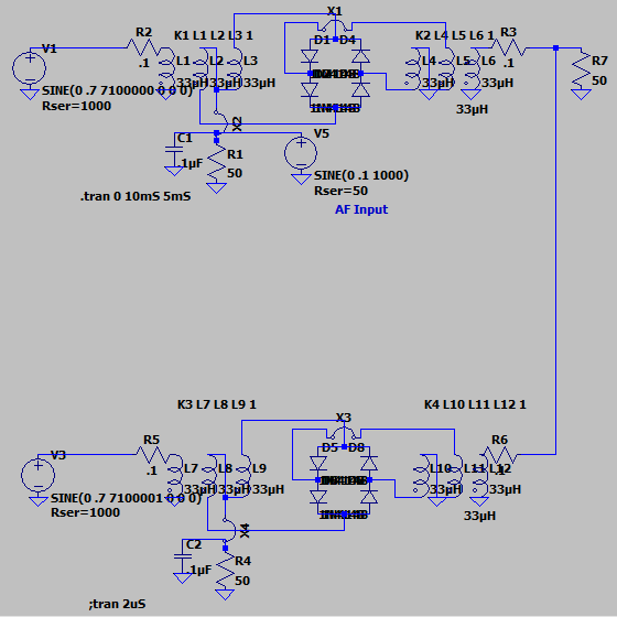
And you can see it in this LTSpice simulation.


This LTSpice model just shows two diode ring mixers. The transmitter is on the top, the receiver is on the bottom. The transmitter has RF at 7100 kHz at L1 and audio at 1 kHz at R1. The receiver has the VFO at 7100.001 L7, DSB from the transmitter at L12 with audio appearing at R4. It is instructive to watch the output as you move the VFO frequency. If you move the VFO freq away from the transmit carrier osc frequency you will see the distortion. Here is the netlist for the LTSpice simulation:


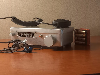
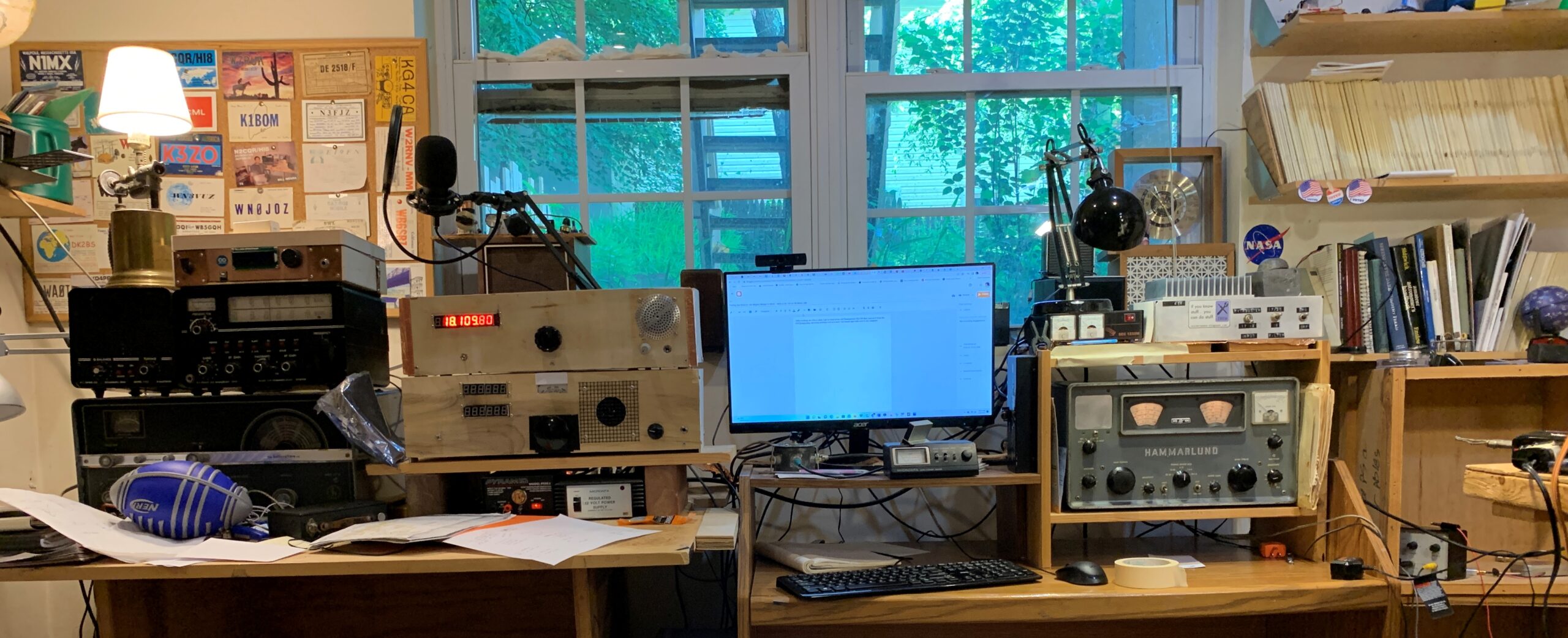
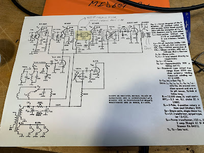
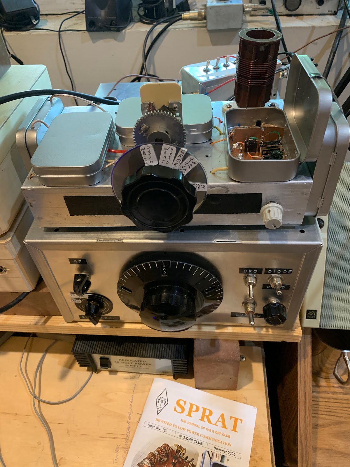
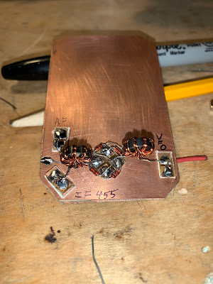
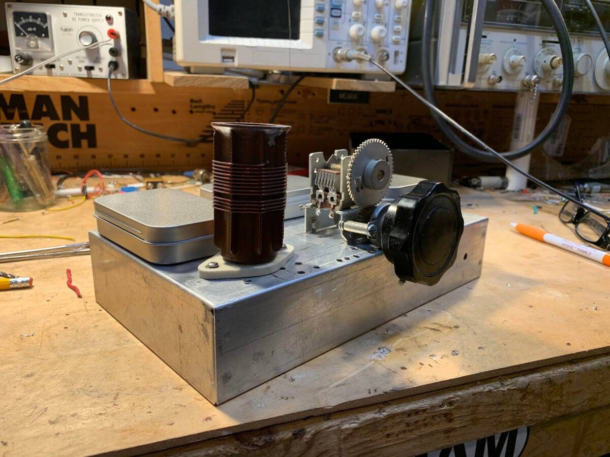
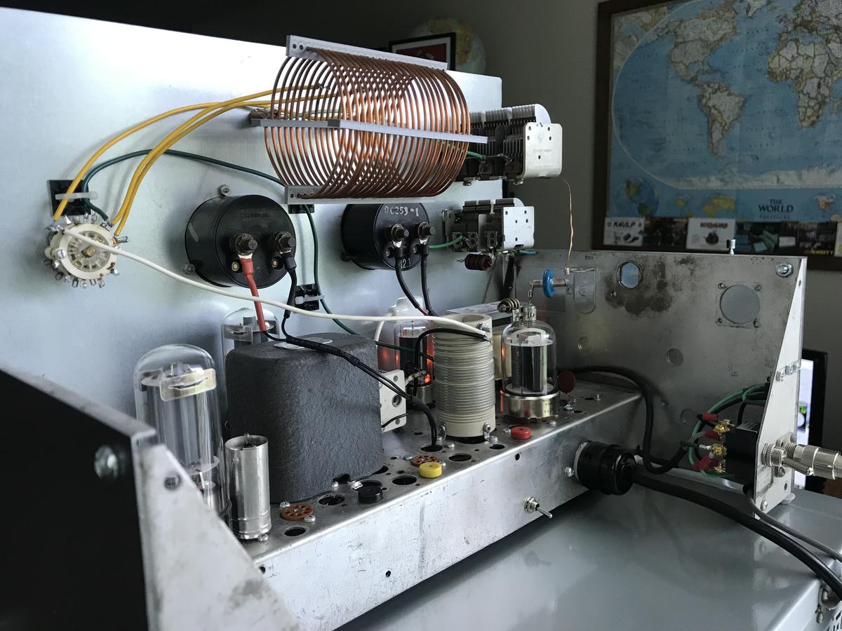
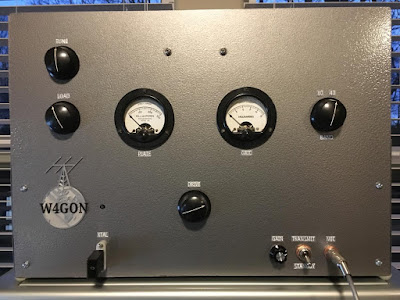
On paper, using simple mixer arithmetic, you can tell that it will be there. With the VFO/PTO just 1 Hz (that’s ONE cycle per second) off, you will end up with outputs at 1.001 kHz and at .999 kHz. Yuck. That won’t sound good. These two different frequencies will be moving in and out of alignment — you will hear them kind of thumping against each other. And that is with a mere deviation of 1 Hz in the VFO/PTO frequency! We are scornful when the SDR guys claim to be able to detect us being “40 Hz off.” And before you start wondering if it would be possible to get EXACTLY on frequency and in phase, take a look at the frequency readout on my PTO.

Now consider what would happen if the incoming signal were SSB, lets say just a tone at 7101 kHz. We’d put our VFO at around 7100 kHz and we’d hear the signal just fine. If we were off a bit we’d hear it a bit higher or lower in tone but there would be no second audio frequency coming in to cause distortion. You can hear this in the VK3YE video: When Peter switches to SINGLE Sideband receiver, the DSB signals sound fine. Because he is receiving only one of the sidebands.

The same thing happens when we try to tune in an AM station using a Direct Conversion receiver: Radio Marti sounds awful on my DC RX, but SSB stations sound great.

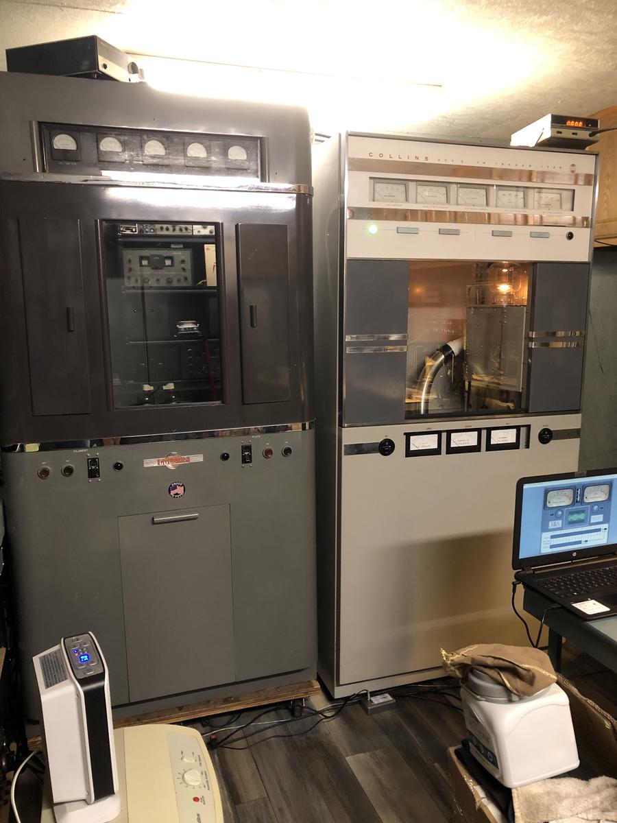
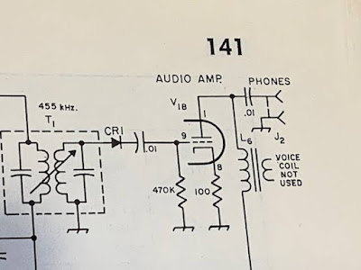
My Drake 2-B allows another opportunity to explore the problem. I can set the bandwidth at 3.6 kHz on the 2-B, and set the passband so that I will be getting BOTH the upper and the lower sidebands of an AM signal. With the Product Detector and the BFO on, even with the carrier at zero beat AM sounds terrible. It sounds distorted. But — with the Product Detector and BFO still on — if I set the 2-B’s passband to only allow ONE of the sidebands through, I can zero beat the carrier by ear, and the audio sounds fine.

There are solutions to this problem: If you REALLY want to listen to DSB with a DC receiver, build yourself a synchronous detector that gets the your receivers VFO EXACTLY on frequency and in phase with the transmitter’s oscillator. But the synchronizing circuitry will be far more complex than the rest of the DC receiver.

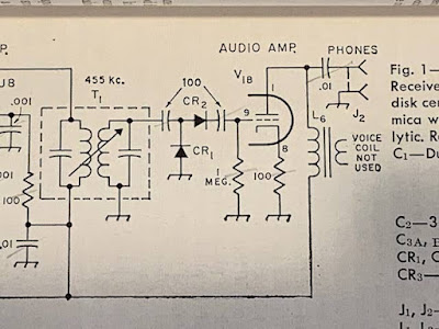
For AM, you could just use a different kind of detector. That will be the subject of an upcoming blog post.

Please let me know if you think I’ve gotten any of this wrong. I’m not an expert — I’m just a ham trying to understand the circuitry.

SolderSmoke Podcast #239: Hex DX, VFO Temp Comp, DC RX, Polyakov!, DX-100, Wireless Set, Farhan’s “Daylight Again” HDR rig, MAILBAG

N2CQR Hex Beam Aimed at Europe


SolderSmoke #239 is available for download:

http://soldersmoke.com/soldersmoke239.mp3

TRAVELOGUE:

James Webb Space Telescope. Mars returning to opposition in early December.

BILL’S BENCH

Hex Beam K4KIO – on roof – TV Rotor – 20-17-12 Lots of fun. Working Japan regularly, Australia, South Africa on long path 17,000 miles. 52 countries SSB since July 11.

VFOs and Temp stabilization. Dean KK4DAS found my ceramic resonator VFO for DC receiver drifty. He was right. So I built a real LC Colpitts VFO. Got me into temp stabilization. A new hobby! An obsession. HT-37 and Ht-32 parts. Ovens? WU2D’s second VFO video. Understanding thermal drift and how to address it. Split stator caps. Cut and try.

Built a Polyakov DC Receiver. https://soldersmoke.blogspot.com/2010/03/polyakov-plus-dual-band-receiver-with.html Lauser Plus. Lauser = Imp or Young Rascal! DK2RS. He used a ceramic Resonator VXO at 3.58 MHz. Mine works great on 40 with VFO running 3.5 — 3.65 MHz. See schematic below.

On 40 AM with DX-100 and MMMRX. DX-100 died. 12BY7 VFO buffer went bad. How common is failure in this tube type? Nice QSO with Tim WA1HLR about the DX-100.

Got my Dominican license: HI7/N2CQR! SSSS on the way. Thanks to Radio Club Dominicano and INDOTEL.

Getting more active in the Vienna Wireless Society.

BOOK REVIEW:

“The History of the Universe in 21 Stars” by Giles Sparrow. Written during the pandemic. Published by Welbeck, in London. https://www.amazon.com/History-Universe-21-Stars-imposters/dp/1787394654 Also: From “Atoms to Amperes” by F.A. Wilson available for download. See blog.

SHAMELESS COMMERCE DIVISION:

Todd K7TFC getting ready to launch “Mostly DIY RF.” I used his TIA boards in my 1712 rig. He will have boards like this and much more. Stay tuned.

I need more viewers on YouTube. They want 4,000 hours IN A CALENDAR YEAR! Please watch!

FARHAN’S NEW “DAYLIGHT AGAIN” RIG. Analog. VFO. Comments, observations. We need to get him on the podcast. Maybe two shows: SDR and HDR.

PETE’S BENCH

Time very limited. But still sharing lots of tribal wisdom.

Wireless set with tubes!

Tool recommendation – Air compressor

MAILBAG:

Farhan VU2ESE – Speaking of big antennas “Whenever I look at the huge construction cranes in Hyderabad, I always think how one could make 160m, 4 element yagi using it as a boom..

Todd K7TFC in Spain, spotting Log Periodics in Madrid.

Andreas DL1AJG: Can Biologists fix Radios?

Janis AB2RA Wireless Girl. Expert on Hammarlunds. And was my first contact with the Tuna Tin 2. She too was HB!

Peter Parker VK3YE on Owen Duffy VK1OD

Lex PH2LB on homebrew radio

Would this really be homebrew? Mail from H-A-D article on FM receiver

F4IET a DSB rig from France

Ciprian got his ticket YO6DXE

Josh G3MOT sent us a good video about the Vanguard satellite and IGY.

Dave Wilcox K8WPE bought Chuck Penson’s Heathkit book.

Rogier — So many great articles and links from PA1ZZ

Bill AH6FC Aloha. Retiring. Wants to build. Mahalo!

Grayson KJ7UM Working on an Si5351. Gasp.

Mike KE0TPE viewing YouTube while monitoring 6 meters. He will have a lot of time to watch!

Chris KD4PBJ spotted Don KM4UDX from VWS FB

Mark WB8YMV building a superhet. Having trouble with 455 kc IF can filter.

Walter KA4KXX Great comment on the Daylight Again rig.

Ramakrishnan Now VU2JXN was VU3RDD. Found lost Kindle with SolderSmoke book on it. Building SDR rig from junk box. Trouble with the LM386.

Pete, Farhan and Tony: Shelves of Shame

Daylight Again by Farhan
The Polyakov receiver I built yesterday (from SPRAT 110, 2002!)

W8ZAP on 40 AM with a Collins 20V3 Broadcast Transmitter

I was on 40 AM yesterday morning and I talked to Jerry W8ZAP (great callsign) out in Michigan. Jerry was running his Collins 20V3 (above on the right), which was originally an AM broadcast band transmitter. FB.

Here is Jerry’s QRZ.com page: https://www.qrz.com/db/W8ZAP

A Great Book on Oscillators (Analog LC Oscillators) by John F. Rider (Free!)

Thanks to Peter Parker VK3YE for alerting us to this wonderful 1940 book. John F. Rider — a real hero of electronic literature — does a great job in discussing the practical aspects of oscillator circuits.

This excerpt from Rider’s foreword gives a sense of the approach taken in this book:

The book covers a lot of material. In addition to the standard oscillator circuits, he discussed multivibrators, relaxation oscillators and much more. There is a chapter on magnetostriction in which he shows that this property is the basis for crystal oscillators AND the mechanical filters that we are familiar with. In fact he seems to take what we would consider a mechanical filter and put it in the grid circuit of a tube to make an oscillator.

He discussed the modulation of oscillators. He describes the Heising modulator that caused young Jean Shepherd so much teenage heartache.

Download the book here:

Putting the “Mate for the Mighty Midget” Back to Work — With a DX-100 on 40 Meter AM

After working on it for a while I got so fond of my old Hammarlund HQ-100 that I moved it from the AM/Boatanchors operating position over to a more convenient spot right next to my computer. This left a big gap on the receive side of the AM station.

I briefly put my HRO-ish solid state receiver above the DX-100, but I’m afraid that receiver needs some work. More on that in due course.

I thought about putting my SOLID STATE Lafayette HA-600A atop the thermatronic DX-100, but this just didn’t seem right. The Radio Gods would NOT approve.

So I turned my attention to the Mate for the Mighty Midget that I built in 1998 and have been poking at and “improving” ever since.

This receiver worked, but not quite right. It received SSB stations well enough, but when I turned off the BFO I could no longer hear the band noise. I wasn’t sure how well the RF amp’s grid and plate tuned circuits tracked. And I had serious doubts about the detector circuit that Lew McCoy put in there when he designed this thing back in 1966.

As I started this latest round of MMMRX poking, I realized that I now have test gear that I didn’t have in 1998: I now have a decent oscilloscope. I have an HP-8640B signal generator (thanks Steve Silverman and Dave Bamford). I have an AADE LC meter. And I’ve learned a lot about building rigs.

FRONT END TRACKING

The MMRX has a tuned circuit in the grid of the RF amplifier, and another in the plate circuit of the RF amplifier. There is a ganged capacitor that tunes them both. They need to cover both 80/75 and 40 meters. And they need to “track” fairly well: over the fairly broad range of 3.5 to 7.3 MHz they both need to be resonant at the same frequency.

McCoy’s article just called for “ten turns on a pill bottle” for the coils in these parallel LC circuits. The link coils were 5 turns. No data on inductance was given. Armed now with an LC meter, I pulled these coils off the chassis and measured the inductances of the coils. I just needed to make sure they were close in value. They were:

L1 was .858uH L2 was 2.709 L3 was .930uH L4 was 2.672

Next I checked the ganged variable capacitors. At first I found that one cap had a lot more capacitance than they other. How could that be? Then I remembered that I had installed trimmer caps across each of the ganged capacitors. Adjusting these trimmers (and leaving the caps connected to the grid of V1a and V2A, I adjusted the trimmers to get the caps close in value. I think I ended up with them fairly close:

C1: 63.77-532 pF C2 64.81 — 525.1 pF

I put the coils back in and checked the tracking on 40 and on 80/75. While not perfect, it was close enough to stop messing with it.

DETECTOR CIRCUIT


I’ve had my doubts about the detector circuit that Lew McCoy had in the MMMRX. In his 1966 QST article he claimed that the circuit he used was a voltage doubler, and that this would boost signal strength. But I built the thing in LT Spice and didn’t notice any doubling. And consider the capacitors he had at the input and output of the detector: 100 pF. At 455 kHz 100 pF is about 3500 ohms. At audio (1 kHz) it is 1.5 MILLION ohms. Ouch. No wonder years ago I put a .1 uF cap across that output cap just to get the receiver working.

Scott WA9WFA told me that by the time the MMMRX appeared in the 1969 ARRL handbook, the second “voltage doubling” diode was gone, as were the 100 pF caps. Now it was just a diode, a .01 uF cap and a 470,000 ohm resistor. I switched to the 1969 Handbook circuit (but I have not yet changed the 1 meg grid resister to 470k — I don’t think this will make much difference). Foiled again by a faulty QST article, again by one of the League’s luminaries.

6U8s out, 6EA8s in

We learned that the 6U8 tubes originally called for by Lew McCoy are getting old and not aging well. So I switched all three to more youthful 6EA8s. This seemed to perk the receiver up a bit.

MUTING from the DX-100

My K2ZA DX-100 has a T/R relay mounted in a box on the back of the transmitter. When the Plate switch goes up, it switches the antenna from receiver to transmitter. The box also has a one pole double throw switch available for receiver muting. I put the common connection to ground, the normally connected (receive position) connect the ground terminal of the AF output transformer to ground — it is disconnected from ground on transmit. The other connection (normally open) is connected to the antenna jack — on transmit this connection ground the receiver RF input connection. These two steps mutes the receiver very nicely.

Replacing Reduction Drive

Over the years I have had several different reduction drives on the main tuning cap. I had a kind of wonky Jackson brothers drive on there that needed to be replaced. I put in a new one — this smoothed out he tuning considerably.

Ceramic Resonator

I never could get McCoy’s 455 kc two crystal filter to work right. So at first I made due with the two 455 kc IF cans. This made for a very broad passband. Then I put a CM filter in there. This was more narrow, but with a lot of loss. There may have been others. But the filter spot is currently held by a 6 kHz wide ceramic filter. This one is my favorite so far.

Digital Readout

When I was running the DX-100 with the Hammarlund HQ-100 I built a little frequency readout box. The box was from a Heath QF-1 Q multiplier (I am sorry about this). The readouts are in Juliano Blue and come via e-bay from San Jian. I now have it hooked up to the DX-100’s oscillator. I haven’t tapped into the MMMRX’s oscillator yet.


HF Bandsweep with the Hammarlund HQ-100 (video)

It has been a while since we last did a bandsweep. Too long. Here is one using my recently fixed up Hammarlund HQ-100. Repair details are in recent videos.

For this bandsweep we cover most of the HF band and even briefly dip down into the AM broadcast band:

Demonstration of the Hammarlund HQ-100: Radio Marti, 40 meter AM, 40 Meter SSB, 40 meter FT-8, 40 meter CW with and without the Q multiplier, classical music on WRMI, WFAX 1220 kHz AM, WWV 20 MHz, CB!, 17 meter SSB, the 20 meter BS position, the effect of AVC and the Noise Limiter, SSB with the internal BFO and with the Q multiplier as BFO. CW with the internal BFO AND the Q multiplier.

Be sure to subscribe to the YouTube channel.

Working On My Old Hammarlund HQ-100 (Part 1)

I like this old receiver, with all its shortcomings. I picked it up in the Dominican Republic in 1993 or 1994. I’ve been using it on AM with my K2ZA DX-100. It needed some contact cleaner, and I took the opportunity to work on a few of the circuits that were getting kind of decrepit.

I came to a new understanding of — and appreciation for — the Q-multiplier.

While of similar vintage, this receiver is MUCH nicer than the Hallicrafters S-38E:
S-38E 1957-61 $54.95 5 tubes. AC/DC, kind of flimsy.
HQ-100 1956-60 $169 10 or 11 tubes. Power supply, regulator, much sturdier construction
You get what you pay for.

In Part II I’ll show you how this thing sounds and what it is like to use it for SWL, CW, SSB and AM.

A Great Morning on the Old Military Radio Net: AB9MQ’s Central Electronics 20A, W3EMD’s Dynamotor, WU2D

Just a portion of Masa’s shack

I usually try to listen in on the Old Military Radio Net on Saturday mornings (3885 kc). Lately I listen with my Mate for the Mighty Midget receiver.

This morning’s session was especially good. For me the highlight was when Masa AB9MQ called in from Normal, Illinois using his Central Electronics 20A (see below). That was one of the earliest SSB rigs. A phasing rig, it also ran AM (which was what Masa was using this morning). He had it paired up with a Central Electronics 458 VFO. You folks really need to check out Masa’s QRZ.com page:

https://www.qrz.com/db/AB9MQ

Buzz W3EMD called in from Rhinebeck, NY. I could hear his dynamotor in the background. Buzz said hello to Masa in Japanese. FB.

Always great to hear Mike WU2D.

2 Meter Homebrew: The Fredbox (Video)

I predict a rebirth of interest in 2 meter homebrew. This will probably hit around Christmas time. The impetus will come out of Hyderabad, India. At this point, I can say no more.

I was thinking about all of this today. I remembered “The Fredbox.” G3XBM’s report on this fantastic rig was carried on this blog before it was even a blog. And the Fredbox goes back much further in time — back to the mid-1970s. It must have been great fun to have QSOs with this rig in Cambridge England back in the day. G3XBM actually crossed the English channel with this 10 mW rig. FB.

When I was in London (2003-2007), G3XBM’s post on the Fredbox got me interested in 2 Meter AM. I had a down-converter that let me listen, and I went as far as modifying a Benton Harbor Lunchbox for the proper AM transmit frequency. I don’t think I made any contacts, but I still have the bits and bobs of this rig, so if anyone in the Northern Virginia area wants to get on, please let me know — I will blow the dust off this project and will build a 2 meter antenna.

Here are more details from G3XBM on The Fredbox:
Hans G0UPL got into the Fredbox in 2009 and 2016:

Mythbuster Videos 8 and 9 — The Old Military Radio Net plus “Zero Beat and The Vertical Skirts”

I like to listen to the Old Military Radio Net on Saturday mornings. This week I was listening with the Mythbuster receiver. The AM carriers provided a good opportunity to observe the effects of the steep skirts of the 10 pole crystal filter. We start at zero beat, with the BFO exactly on the carrier frequency. If I turn the VFO dial in one direction, I in effect move the passband in a way that puts the carrier in the passband. And it is no longer zero beat with the BFO, so we hear the heterodyne (the beat!). But if I turn the VFO dial in the other direction, the carrier is now outside the passband. Even though the BFO would produce a tone, we don’t hear a tone, because those steep filter skirts are keeping the carrier out. We do continue to hear some of the sideband frequencies, because they remain in the passband. The very sharp drop-off of the carrier tone is a good indication that the steep skirts of the crystal filter are doing the job.

“Zero Beat and the Vertical Skirts” Sounds like the name of a Punk Rock band, doesn’t it? Anyway in this video I explain what happened in Mythbuster Video #8 (above). I explain why we can hear the Old Military Radio Net carriers when I tune the VFO in one direction, but not in the other.

The Ceramic Spurs (not a rock group)

Paul Taylor VK3HN’s magnificent AM receiver was the inspiration for my Quarantine-31 Shortwave Broadcast receiver. Like Paul I decided to make use of ceramic filters at 455 kHz for selectivity. I started with the +/- 3 kHz filters that Paul used, but I found them kind of narrow for SW listening. So I went with some wider ceramic filters that Bruce KK0S had sent me. But I misread the specs that Bruce sent. I thought they were 10 kHz wide filters. I realized later that they were +/- 10 kHz — really twice as wide as I needed. So I went back to Mini-Kits in Australia and got some +/- 6 kHz filters. 12 kc wide should be just about right, I thought.

The bandwidth was right, but I started noticing a problem: I could hear strong SW broadcast stations at two places on my dial. This brought to mind an admonition from R.A Penfold, author of “Short Wave Superhet Receiver Construction” (1991 Babani Publications). He advised keeping a few standard 455 kc IF cans in the circuit because, he warned, the ceramic filters have spurious responses, spurs that the IF cans can help knock down.

Penfold was right. Look at the filter response curve on the right (above). There is a nasty spur at around 640 kHz. This was the cause of my problem. Here is why:

Suppose I was tuning Radio Marti’s big signal on 9805 kc. My VFO would be running at 9350 kc.
9805-9350=455. Great, but…
With that spur at 640 kc, I could tune down to 9620 kc on my dial. My VFO would be running at 9165 kc.
9805-9165=640. Bad. That 640 kc difference product would make it through to my detector and AF amp. I’d have Radio Marti showing up in two places. I didn’t like this.

I thought about putting a series LC circuit tuned to 640 kc at the output of the ceramic filter. This looked like a possible solution, but on the bench it looked like I would have trouble getting a circuit of sufficiently high Q.

So rummaging around in my junk box I found an old Murata CFM455B filter. This filter is quite broad, but it does not have the spur at 640 kc. I could use it as a kind of roofing filter just ahead of the +/- 6 kHz filter. Putting it there would allow me to avoid having to build additional matching circuits for the 455B filter.

+/-6kc filter upper left, 455B wide filter to the lover right.

I’m happy to report that this fix works. The 6 kc filter provides the needed selectivity, and the broader 455B filter knocks down the 640 kc spur.

Beware the Ceramic Spurs!

Q-31 with can for first IF amps and filters open

Q-31 Quarantine Receiver — All Boxed Up, Almost Done

Almost done. A few odds and ends remain, but now I have all the circuitry in their boxes.

As I was taking my walk the other day I was thinking of how I didn’t have to build a BFO for this superhet. That’s because the signals coming in on this rig bring with them their own BFO signal (the carrier).

Quarantine Rig Q-31 — Putting the Stages Together (Most of Them)

I’ve been recording short videos on my progress with the Q-31 Shortwave AM Quarantine Receiver.

Yesterday was a bit of a milestone — I put five of the six sub-assemblies together and did some testing. You can see the video above.

All the other videos are on my YouTube site:

https://www.youtube.com/user/M0HBR

Please subscribe and give me a “thumbs up.”

SITS! Stay in the shack! Flatten the curve. Hang in there. 73 Bill

Videos on the Q-31 Quarantine AM SW Receiver Project (and some pictures)

I’ve been making some short, stage-by-stage videos of my Q-31 receiver project. So far I have seven videos. They are here:

https://www.youtube.com/user/M0HBR/videos

Please subscribe to my YouTube Channel. And give me some “thumbs up” if you like the videos.

Thanks. SITS! FlattenTheCurve! 73

Pads from Pete, toroids from Farhan
The diode ring
Altoids-sized tins will hold the circuit boards
Stay In The Shack — Or in the front yard.


Quarantine Project: An AM Receiver for the 31 Meter Band. The Q-31.

During this StayInTheShack (SITS) emergency, it is good to have something to work on. I decided it would be best to try to build something using only items currently in my parts collection. I’ve been getting into shortwave listening again, and I’ve discovered that the 31 meter band (9.4 – 9.9 MHz) is my favorite. Thus the “Quarantine On-Hand 31 Meter AM Receiver.” A big part of the inspiration for this project comes from the AM receiver of Paul VK3HN.

I propose that we all designate rigs built during quarantine as “Q” rigs. This will be the Q-31.

I had an old chassis on the shelf. It held my WSPR DSB rig in Rome, and various other projects over the years. It has so many holes in it that it looks like it has been used for target practice.

A while back Pete N6QW sent me this really magnificent variable capacitor with at least two reduction dries and an anti-backlash gear. I’ve been looking for a project that will allow me to use AND display this beautiful part. It will be the main tuning cap for the Q-39. It will stay — like the tubes in the rigs of days-gone-by — above the chassis.

While in London many years ago I picked up an old regen receiver at the Kempton Park rally. The parts are still in my junk box. A very nice 1.7 uH plug in coil (with socket) was there. That will be the main coil in the Hartley Oscillator that will be the VFO. I will add a few turns for the feedback coil (see circuit diagram below). I wonder of that Eddystone coil was around for the Blitz?

On the recommendation of our old friend Rogier (originally PA1ZZ), a few years ago Elisa got me a set of grey Altoids-sized metal boxes. I will have three of these atop the target-practice chassis (they will provide shielding and will cover up the holes):

— One will hold the bandpass filter (designed with the Elsie program) and the mixer (probably diode ring, with transformers from Farhan).

— One will hold two IF amps with a 10 kHz 455 kHz IF filter between them (thanks to Bruce KK0S for the filters).

— One will hold the AM detector and the AF amplifiers.

— A fourth box will be under the chassis and will hold all the powered parts of the VFO circuitry. I base my VFOs on this simple circuit from page 34 of Solid State Design for the Radio Amateur:


This quarantine looks like it is going to last a long time, so it is best to take your time on projects like this. I might work on the VFO today. No need to rush…

I am shooting videos as I go along and will at some point start putting them up on my YouTube channel.

So, I suggest that any of you who are feeling bored and confined (that would be almost all of us) fight back by launching a Quarantine “Q-Rig” project. Send reports to me — I will try to put them on the SolderSmoke blog.

Remember: StayInThe Shack! #SITS! #flattenthecurve.

73 Bill

VK3HN’s AM Pulse Width Modulated Homebrew Transmitter

I’m still working on trying to match the excellent results Paul achieved with his AM receiver. Then this morning I wake up to a Hack-A-Day article describing his even more impressive achievement with his AM transmitter.

There was one line from the Hack-A-Day article that made me think of Pete Juliano:

Younger hackers will note the Arduino Nano at the heart of the project, running the VFO and handling all the relevant transmit/receive switching. We can only imagine how welcome modern microcontrollers must have been to old hands at amateur radio, making synthesizing all manner of wild frequencies a cinch.

Indeed.

And once again this story about Paul’s AM operations has made me jealous of the obviously great AM homebrew culture that exists in Australia.

FB Paul!


TRGHS: Hallicrafters S-38E will NOT be Discarded (video)

My Hallicrafters S-38E was on very thin ice. I had grown tired of the little beast. Its dangerous no-transformer power supply had caused me to risk death and to fry one of the RF input coils (that happens if you short the antenna input to an inadvertently hot chassis). It is rickety and old and I just got tired of working on it. I had down in the basement, awaiting disposal of some kind. (I’d been afraid to give it away, fearing that the recipient might electrocute himself.) But recently I’ve been doing some shortwave listening and this caused me to reconsider the S-38E.

Around this time, while looking at e-bay, I saw some guy selling just the RF input coil that I had fried. So I bought it. Then I pulled the S38-E out of the basement and fired it up. I realized that I had already done a lot of work on it. I had put in an isolation transformer, so the receiver was no longer quite so dangerous. I’d already replaced most of the capacitors. It sounded pretty good on the AM broadcast band. Then, in my first scan of the shortwave bands, I heard the William Tell Overture pouring from the speaker (see video). Could it be? Perhaps a replay of the Jean Shepherd show? No, but I soon heard the familiar voice of Tim WA1HLR — he was doing his show on (I think) WBCQ shortwave, just above our 40 meter band.

THE RADIO GODS HAVE SPOKEN. THE S-38E STAYS!

AM Rally Report — Great Contacts on 40 AM

The AM Rally this past weekend was a lot of fun. I was reminded of how the guys that you talk to on AM are just so much more likely to be running interesting homebrew or vintage gear.

First contact was with Howard VE2AED who has one of the most amazing antenna farms I have ever seen. Take a look:
https://www.qrz.com/db/VE2AED
He also has an R-390 and a KWM2 in his shack.

Next I spoke to Robert W0VMC (Voice Modulated Carrier) out in Wisconsin. Robert is a homebrewer of AM gear with a Knack story that is very familiar: http://w0vmc.com/

Next up was W4GON. Joel was on the homebrew AM transmitter that we reported on back in 2017:
https://soldersmoke.blogspot.com/2017/08/thermatrons-al-fresco-w4gons-fb-hb-am.html

Joel has completed his rig, adding a FB front panel. Here it is:

Then came the W1AW contact. See the video above.

Finally, I talked to Jack W9GT who was running a rig that must be unique on the amateur bands: A Federal 167 B Maritime transmitter. You can see this magnificent transmitter here: